wheel RAM PROMASTER CITY 2022 Owners Manual
[x] Cancel search | Manufacturer: RAM, Model Year: 2022, Model line: PROMASTER CITY, Model: RAM PROMASTER CITY 2022Pages: 260, PDF Size: 8.45 MB
Page 4 of 260
2
INTRODUCTION
SYMBOLS KEY ...........................................................7
VAN CONVERSIONS/CAMPERS ..............................7
VEHICLE MODIFICATIONS/ALTERATIONS .............7
SYMBOL GLOSSARY.................................................8
GETTING TO KNOW YOUR VEHICLE
KEYS ....................................................................... 10 Key Fob .............................................................10
SENTRY KEY ........................................................... 12
IGNITION SWITCH .................................................. 12
DOORS ................................................................... 13
Power Door Locks ............................................13
Auto Unlock Doors ............................................13
Sliding Side Door ..............................................13
Double Rear Swing Doors ................................15
Child-Protection Door Lock System.................15
STEERING WHEEL.................................................. 16
Tilt/Telescoping Steering Column ...................16
SEATS ...................................................................... 16
Manual Adjustment (Front Seats) ...................16
Folding Rear Seat — If Equipped .....................17
Heated Seats — If Equipped ............................18
Head Restraints ...............................................19 UCONNECT VOICE RECOGNITION ........................21
Introducing Voice Recognition.........................21
Basic Voice Commands ...................................21
Get Started .......................................................21
Additional Information .....................................21
MIRRORS ...............................................................22
Inside Rearview Mirror .....................................22
Vanity Mirror .....................................................22
Outside Mirrors ................................................22
EXTERIOR LIGHTS ..................................................24
Multifunction Lever ..........................................24
Headlights ........................................................24
Daytime Running Lights (DRLs) —
If Equipped .......................................................24
High/Low Beam Switch....................................24
Flash-To-Pass ..................................................24
Parking Lights ..................................................24
Follow Me Home/Headlight Delay ..................24
Fog Lights — If Equipped .................................25
Turn Signals ......................................................25
Lane Change Assist..........................................25
INTERIOR LIGHTS ..................................................25
Courtesy/Interior Lights ...................................25
WIPERS AND WASHERS ......................................26
Front Wiper Operation......................................27
Rear Wiper And Washer —If Equipped ............28 CLIMATE CONTROLS ............................................ 28
Manual Climate Control Descriptions And
Functions .......................................................... 28
Operating Tips .................................................. 30
INTERIOR STORAGE AND EQUIPMENT ............... 31
Storage ............................................................. 31
USB Control — If Equipped .............................. 32
Power Outlets .................................................. 32
WINDOWS ............................................................. 34
Power Window Controls —If Equipped ........... 34
Window Bar Grates — If Equipped .................. 35
Wind Buffeting .................................................35
HOOD....................................................................... 36
Opening............................................................. 36
Closing ..............................................................36
CARGO AREA FEATURES ...................................... 37
Rear Cargo Tie-Downs ..................................... 37
ROOF RACK — IF EQUIPPED................................. 37
GETTING TO KNOW YOUR
INSTRUMENT PANEL
INSTRUMENT CLUSTER......................................... 39
Instrument Cluster Descriptions ..................... 40
INSTRUMENT CLUSTER DISPLAY ....................... 40
Location And Controls...................................... 40
Change Engine Oil — If Equipped ................... 41
Instrument Cluster Display Menu Items ......... 42
22_VM_OM_EN_USC_t.book Page 2
Page 6 of 260
4
MULTIMEDIA
UCONNECT SYSTEMS ........................................... 78
CYBERSECURITY ................................................... 78
UCONNECT SETTINGS .......................................... 79 Uconnect 3/3 NAV Settings .............................79
UCONNECT INTRODUCTION.................................. 88
Identifying Your Radio ......................................88
Safety And General Information ......................90
UCONNECT MODES ............................................... 91
Radio Mode ......................................................91
Media Mode......................................................98
Phone Mode ................................................. 100
NAVIGATION MODE — IF EQUIPPED ..................110
Operating Navigation Mode —If Equipped ... 110
STEERING WHEEL AUDIO CONTROLS —
IF EQUIPPED ........................................................ 128
Radio Operation ............................................ 128
Media Mode................................................... 129
RAM TELEMATICS - IF EQUIPPED ...................... 129
Ram Telematics General Information .......... 129
RADIO OPERATION AND MOBILE PHONES ..... 130
Regulatory And Safety Information .............. 130
SAFETY
SAFETY FEATURES .............................................. 131Four-Wheel Anti-Lock Brake System (ABS).. 131
Electronic Brake Control (EBC) System ...... 132
AUXILIARY DRIVING SYSTEMS.......................... 135
Tire Pressure Monitoring System (TPMS) .... 135
OCCUPANT RESTRAINT SYSTEMS ................... 137
Occupant Restraint Systems ........................ 137
Important Safety Precautions ...................... 137Seat Belt Systems ........................................ 138Supplemental Restraint Systems (SRS) ...... 144Child Restraints ............................................. 152
SAFETY TIPS ....................................................... 168
Transporting Passengers .............................. 168Transporting Pets ......................................... 168
Safety Checks You Should Make Inside
The Vehicle ................................................... 168
Periodic Safety Checks You Should Make
Outside The Vehicle ...................................... 169
Exhaust Gas................................................... 170
Carbon Monoxide Warnings ........................ 170
IN CASE OF EMERGENCY
HAZARD WARNING FLASHERS......................... 171
JACKING AND TIRE CHANGING ......................... 171
Preparations For Jacking ............................. 171
Jack Location — If Equipped ......................... 172
Removing The Spare Tire —If Equipped....... 172 Jacking Instructions ...................................... 174
Vehicles With Alloy Wheels ........................... 177
Vehicles Equipped With Wheel Covers ........ 178
TIRE SERVICE KIT — IF EQUIPPED .................... 179
Tire Service Kit Storage ................................ 179Tire Service Kit Usage ................................... 179
JUMP STARTING .................................................. 181
Preparations For Jump Starting ................... 181Jump Starting Procedure .............................. 182
IF YOUR ENGINE OVERHEATS ........................... 183
IGNITION KEY REMOVAL OVERRIDE ................. 184
GEAR SELECTOR OVERRIDE .............................. 184
FREEING A STUCK VEHICLE .............................. 185
TOWING A DISABLED VEHICLE .......................... 187
ENHANCED ACCIDENT RESPONSE SYSTEM
(EARS) .................................................................. 188
EVENT DATA RECORDER (EDR) ......................... 188
SERVICING AND MAINTENANCE
SCHEDULED SERVICING .................................... 189
Maintenance Plan ......................................... 190
ENGINE COMPARTMENT .................................... 193
Engine Compartment — 2.4L ....................... 193
Checking Oil Level ........................................ 194
Adding Washer Fluid .................................... 194
Maintenance-Free Battery ........................... 194
Pressure Washing ......................................... 195
22_VM_OM_EN_USC_t.book Page 4
Page 7 of 260
5
VEHICLE MAINTENANCE ..................................... 195 Engine Oil ....................................................... 195
Engine Oil Filter ............................................. 196
Engine Air Cleaner Filter .............................. 196Air Conditioner Maintenance ....................... 196
Body Lubrication............................................ 197
Windshield Wiper Blades .............................. 197Exhaust System ............................................ 198
Cooling System ............................................. 199
Brake System ............................................... 202
Automatic Transmission .............................. 203Upfitter Connectors — If Equipped ............... 204
Fuses.............................................................. 207
Bulb Replacement ......................................... 213
TIRES ..................................................................... 217
Tire Safety Information ................................ 217
Tires — General Information ........................ 225
Tire Types ....................................................... 228
Spare Tires — If Equipped ............................. 229
Wheel And Wheel Trim Care ........................ 231
Tire Chains and Traction Devices ................ 232
Tire Rotation Recommendations ................. 232
DEPARTMENT OF TRANSPORTATION UNIFORM
TIRE QUALITY GRADES ...................................... 232
Treadwear ...................................................... 232Traction Grades ............................................. 233
Temperature Grades ..................................... 233
STORING THE VEHICLE ...................................... 233 BODYWORK ......................................................... 233
Protection From Atmospheric Agents .......... 233
Body And Underbody Maintenance.............. 234Preserving The Bodywork ............................. 234
INTERIORS .......................................................... 235
Seats And Fabric Parts ................................. 235
Plastic And Coated Parts .............................. 235Leather Surfaces ........................................... 235Glass Surfaces ............................................. 235
TECHNICAL SPECIFICATIONS
VEHICLE IDENTIFICATION NUMBER (VIN) ........ 236
BRAKE SYSTEM ................................................... 236
WHEEL AND TIRE TORQUE SPECIFICATIONS .. 236
Torque Specifications ................................... 236
FUEL REQUIREMENTS ........................................ 237
2.4L Engine ................................................... 237
Reformulated Gasoline ................................ 238Gasoline/Oxygenate Blends ........................ 238
E-85 Usage In Non-Flex Fuel Vehicles ......... 238CNG And LP Fuel System Modifications ...... 238MMT In Gasoline ........................................... 238Materials Added To Fuel ............................... 239
Fuel System Cautions ................................... 239
FLUID CAPACITIES ............................................. 240
ENGINE FLUIDS AND LUBRICANTS................... 240
CHASSIS FLUIDS AND LUBRICANTS ................ 241
CUSTOMER ASSISTANCE
SUGGESTIONS FOR OBTAINING SERVICE FOR
YOUR VEHICLE .................................................... 242
Prepare For The Appointment ...................... 242
Prepare A List ................................................ 242
Be Reasonable With Requests..................... 242
IF YOU NEED ASSISTANCE ................................ 242
FCA US LLC Customer Center....................... 242
FCA Canada Inc. Customer Center .............. 242
Mexico............................................................ 243
Puerto Rico And US Virgin Islands ............... 243
Customer Assistance For The Hearing
Or Speech Impaired (TDD/TTY) .................... 243
Service Contract ........................................... 243
WARRANTY INFORMATION ................................ 244
MOPAR® PARTS ................................................. 244
REPORTING SAFETY DEFECTS .......................... 244
In The 50 United States And
Washington, D.C............................................ 244
In Canada ...................................................... 244
PUBLICATION ORDER FORMS .......................... 245
GENERAL INFORMATION.................................... 245
22_VM_OM_EN_USC_t.book Page 5
Page 18 of 260
16GETTING TO KNOW YOUR VEHICLE
NOTE:For emergency exit from the rear seats when the
Child-Protection Door Lock system is engaged,
manually raise the door lock knob to the unlocked
position, roll down the window, and open the door
using the outside door handle.
STEERING WHEEL
TILT/TELESCOPING STEERING COLUMN
This feature allows you to tilt the steering column
upward or downward. It also allows you to lengthen
or shorten the steering column. The steering
column control is located on the steering column,
below the turn signal lever.
Steering Column Control
To unlock the steering column, push the steering
column control downward. To tilt the steering
column, move the steering wheel upward or downward as desired. To lengthen or shorten the
steering column, pull the steering wheel outward
or push it inward as desired. To lock the steering
column in position, pull the steering column
control up until fully engaged.
SEATS
Seats are a part of the Occupant Restraint system
of the vehicle.
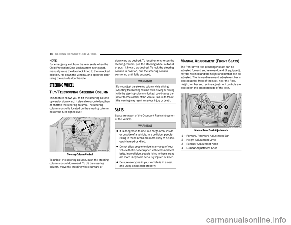
MANUAL ADJUSTMENT (FRONT SEATS)
The front driver and passenger seats can be
adjusted forward and rearward, and (if equipped),
may be reclined and the height and lumbar can be
adjusted. The forward/rearward adjustment bar is
located at the front of the seat, near the floor.
Height, lumbar and recline adjustment controls are
located on the outboard side of the seat.
Manual Front Seat Adjustments
WARNING!
Do not adjust the steering column while driving.
Adjusting the steering column while driving or driving
with the steering column unlocked, could cause the
driver to lose control of the vehicle. Failure to follow
this warning may result in serious injury or death.
WARNING!
It is dangerous to ride in a cargo area, inside
or outside of a vehicle. In a collision, people
riding in these areas are more likely to be seri -
ously injured or killed.
Do not allow people to ride in any area of your
vehicle that is not equipped with seats and seat
belts. In a collision, people riding in these areas
are more likely to be seriously injured or killed.
Be sure everyone in your vehicle is in a seat
and using a seat belt properly.
1 — Forward/Rearward Adjustment Bar
2 — Height Adjustment Lever
3 — Recliner Adjustment Knob
4 — Lumbar Adjustment Knob
22_VM_OM_EN_USC_t.book Page 16
Page 26 of 260
24GETTING TO KNOW YOUR VEHICLE
EXTERIOR LIGHTS
MULTIFUNCTION LEVER
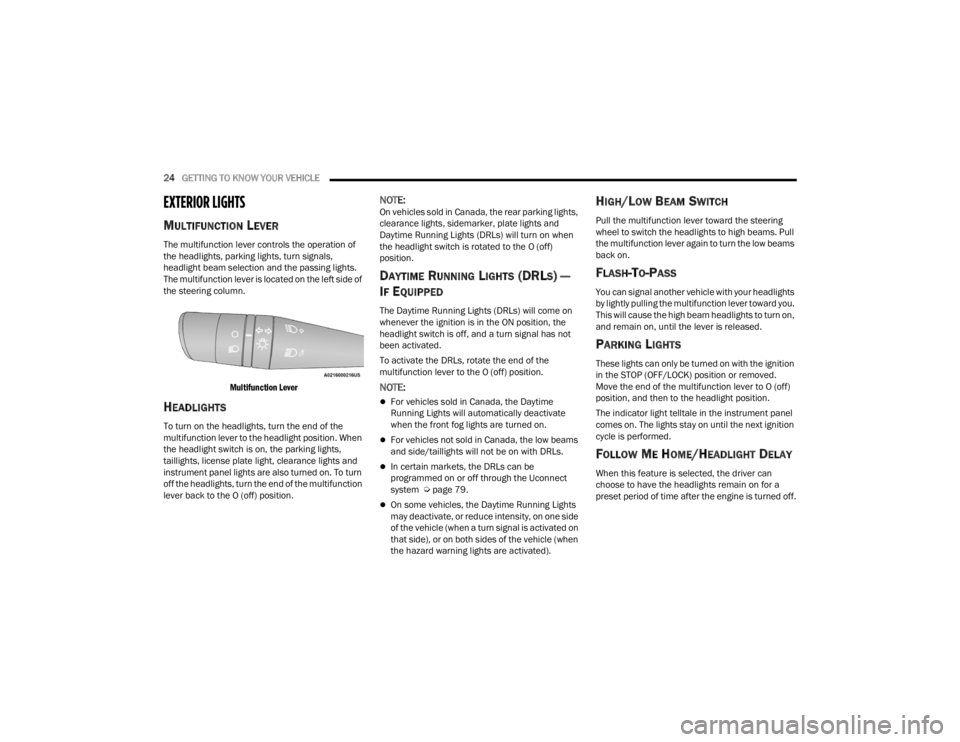
The multifunction lever controls the operation of
the headlights, parking lights, turn signals,
headlight beam selection and the passing lights.
The multifunction lever is located on the left side of
the steering column.
Multifunction Lever
HEADLIGHTS
To turn on the headlights, turn the end of the
multifunction lever to the headlight position. When
the headlight switch is on, the parking lights,
taillights, license plate light, clearance lights and
instrument panel lights are also turned on. To turn
off the headlights, turn the end of the multifunction
lever back to the O (off) position.
NOTE:On vehicles sold in Canada, the rear parking lights,
clearance lights, sidemarker, plate lights and
Daytime Running Lights (DRLs) will turn on when
the headlight switch is rotated to the O (off)
position.
DAYTIME RUNNING LIGHTS (DRLS) —
I
F EQUIPPED
The Daytime Running Lights (DRLs) will come on
whenever the ignition is in the ON position, the
headlight switch is off, and a turn signal has not
been activated.
To activate the DRLs, rotate the end of the
multifunction lever to the O (off) position.
NOTE:
For vehicles sold in Canada, the Daytime
Running Lights will automatically deactivate
when the front fog lights are turned on.
For vehicles not sold in Canada, the low beams
and side/taillights will not be on with DRLs.
In certain markets, the DRLs can be
programmed on or off through the Uconnect
system Ú page 79.
On some vehicles, the Daytime Running Lights
may deactivate, or reduce intensity, on one side
of the vehicle (when a turn signal is activated on
that side), or on both sides of the vehicle (when
the hazard warning lights are activated).
HIGH/LOW BEAM SWITCH
Pull the multifunction lever toward the steering
wheel to switch the headlights to high beams. Pull
the multifunction lever again to turn the low beams
back on.
FLASH-TO-PASS
You can signal another vehicle with your headlights
by lightly pulling the multifunction lever toward you.
This will cause the high beam headlights to turn on,
and remain on, until the lever is released.
PARKING LIGHTS
These lights can only be turned on with the ignition
in the STOP (OFF/LOCK) position or removed.
Move the end of the multifunction lever to O (off)
position, and then to the headlight position.
The indicator light telltale in the instrument panel
comes on. The lights stay on until the next ignition
cycle is performed.
FOLLOW ME HOME/HEADLIGHT DELAY
When this feature is selected, the driver can
choose to have the headlights remain on for a
preset period of time after the engine is turned off.
22_VM_OM_EN_USC_t.book Page 24
Page 27 of 260
GETTING TO KNOW YOUR VEHICLE25
Activation
Remove the key or turn the ignition to the STOP
(OFF/LOCK) position, and pull the multifunction
lever toward the steering wheel within two
minutes. Each time the lever is pulled, the
activation of the lights will be extended by 30
seconds. The activation of the lights can be
extended to a maximum of 210 seconds.
Deactivation
Pull the multifunction lever toward the steering
wheel and hold it for more than two seconds.
FOG LIGHTS — IF EQUIPPED
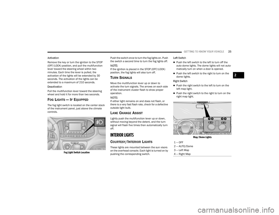
The fog light switch is located on the center stack
of the instrument panel, just above the climate
controls.
Fog Light Switch Location
Push the switch once to turn the fog lights on. Push
the switch a second time to turn the fog lights off.
NOTE:If the ignition is placed in the STOP (OFF/LOCK)
position, the fog lights will also turn off.
TURN SIGNALS
Move the multifunction lever up or down to
activate the turn signals. The arrows on each side
of the instrument cluster flash to show proper
operation.
NOTE:If either light remains on and does not flash, or
there is a very fast flash rate, check for a defective
outside light bulb.
LANE CHANGE ASSIST
Lightly push the multifunction lever up or down,
without moving beyond the detent, and the turn
signal will flash five times then automatically turn
off.
INTERIOR LIGHTS
COURTESY/INTERIOR LIGHTS
These lights are mounted between the sun visors
on the overhead console. Each light is turned on by
pushing the corresponding switch. Left Switch
Push the left switch to the left to turn off the
auto dome lights. The dome lights will not auto -
matically turn on when a door is opened.
Push the left switch to the right to turn on the
dome lights.
Right Switch
Push the right switch to the left to turn on the
left map light.
Push the right switch to the right to turn on the
right map light.
Map/Dome Lights
1 — OFF
2 — AUTO/Dome
3 — Left Map
4 — Right Map
2
22_VM_OM_EN_USC_t.book Page 25
Page 32 of 260
30GETTING TO KNOW YOUR VEHICLE
Mode Control
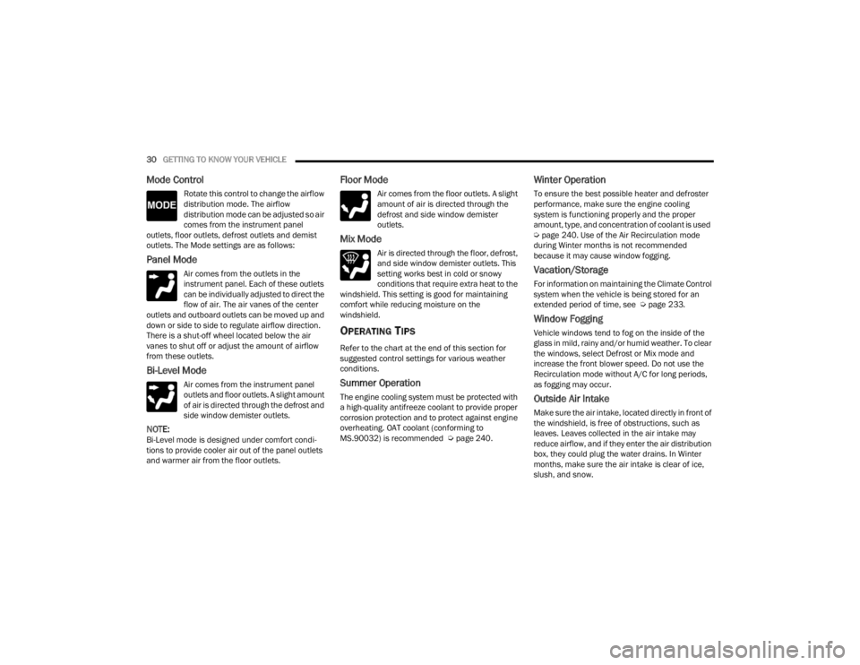
Rotate this control to change the airflow
distribution mode. The airflow
distribution mode can be adjusted so air
comes from the instrument panel
outlets, floor outlets, defrost outlets and demist
outlets. The Mode settings are as follows:
Panel Mode
Air comes from the outlets in the
instrument panel. Each of these outlets
can be individually adjusted to direct the
flow of air. The air vanes of the center
outlets and outboard outlets can be moved up and
down or side to side to regulate airflow direction.
There is a shut-off wheel located below the air
vanes to shut off or adjust the amount of airflow
from these outlets.
Bi-Level Mode
Air comes from the instrument panel
outlets and floor outlets. A slight amount
of air is directed through the defrost and
side window demister outlets.
NOTE:Bi-Level mode is designed under comfort condi -
tions to provide cooler air out of the panel outlets
and warmer air from the floor outlets.
Floor Mode
Air comes from the floor outlets. A slight
amount of air is directed through the
defrost and side window demister
outlets.
Mix Mode
Air is directed through the floor, defrost,
and side window demister outlets. This
setting works best in cold or snowy
conditions that require extra heat to the
windshield. This setting is good for maintaining
comfort while reducing moisture on the
windshield.
OPERATING TIPS
Refer to the chart at the end of this section for
suggested control settings for various weather
conditions.
Summer Operation
The engine cooling system must be protected with
a high-quality antifreeze coolant to provide proper
corrosion protection and to protect against engine
overheating. OAT coolant (conforming to
MS.90032) is recommended Ú page 240.
Winter Operation
To ensure the best possible heater and defroster
performance, make sure the engine cooling
system is functioning properly and the proper
amount, type, and concentration of coolant is used
Úpage 240. Use of the Air Recirculation mode
during Winter months is not recommended
because it may cause window fogging.
Vacation/Storage
For information on maintaining the Climate Control
system when the vehicle is being stored for an
extended period of time, see Ú page 233.
Window Fogging
Vehicle windows tend to fog on the inside of the
glass in mild, rainy and/or humid weather. To clear
the windows, select Defrost or Mix mode and
increase the front blower speed. Do not use the
Recirculation mode without A/C for long periods,
as fogging may occur.
Outside Air Intake
Make sure the air intake, located directly in front of
the windshield, is free of obstructions, such as
leaves. Leaves collected in the air intake may
reduce airflow, and if they enter the air distribution
box, they could plug the water drains. In Winter
months, make sure the air intake is clear of ice,
slush, and snow.
22_VM_OM_EN_USC_t.book Page 30
Page 40 of 260
38GETTING TO KNOW YOUR VEHICLE
(Continued)
To move the crossbars, loosen the attachments,
located at the upper edge of each crossbar,
approximately eight turns using the anti-theft
wrench provided with the Mopar® crossbars.
Then, move the crossbar to the desired position,
keeping the crossbars parallel to the rack frame.
Once the crossbar is in the desired position,
re-tighten it with the wrench to lock the crossbar
into position.
NOTE:
To help control wind noise when the crossbars
are not in use, place the front and rear cross
-
bars approximately 24 inches (61 cm) apart.
Optimal noise reduction can then be achieved
by adjusting the front crossbar forward or aft
using increments of 1 inch (2.5 cm).
If the crossbar (or any metallic object) is placed
over the satellite radio antenna (if equipped),
you may experience interruption of satellite
radio reception. For improved satellite radio
reception, avoid placing the rear crossbar over
the satellite radio antenna.
WARNING!
Cargo must be securely tied down before driving
your vehicle. Improperly secured loads can fly off
the vehicle, particularly at high speeds, resulting
in personal injury or property damage. Follow
the roof rack cautions when carrying cargo on
your roof rack.
CAUTION!
To prevent damage to the roof of your vehicle,
DO NOT carry any loads on the roof rack
without the crossbars deployed. The load
should be secured and placed on top of the
crossbars, not directly on the roof. If it is
necessary to place the load on the roof, place
a blanket or other protective layer between
the load and the roof surface.
To avoid damage to the roof rack and vehicle,
do not exceed the maximum roof rack load
capacity of 150 lb (68 kg). Always distribute
heavy loads as evenly as possible and secure
the load appropriately.
Loads should always be secured to crossbars
first, with tie down loops used as additional
securing points if needed. Tie loops are
intended as supplementary tie down points
only. Do not use ratcheting mechanisms with
the tie loops. Check the straps and thumb
wheels frequently to be sure that the load
remains securely attached.
Long loads that extend over the windshield,
such as wood panels or surfboards, or loads
with large frontal area should be secured to
both the front and rear of the vehicle.
Travel at reduced speeds and turn corners
carefully when carrying large or heavy loads
on the roof rack. Wind forces, due to natural
causes or nearby truck traffic, can add sudden
upward lift to a load. This is especially true on
large flat loads and may result in damage to
the cargo or your vehicle.
CAUTION!
22_VM_OM_EN_USC_t.book Page 38
Page 42 of 260
40GETTING TO KNOW YOUR INSTRUMENT PANEL
INSTRUMENT CLUSTER DESCRIPTIONS
1. Speedometer
Indicates vehicle speed.
2. Fuel Gauge
The pointer shows the level of fuel in the
fuel tank when the ignition switch is in the
ON/RUN position.
The fuel pump arrow symbol
points to the side of the vehicle
where the fuel door is located.
3.Temperature Gauge
The temperature gauge shows engine
coolant temperature. Any reading within the
normal range indicates that the engine
cooling system is operating satisfactorily.
The pointer will likely indicate a higher
temperature when driving in hot weather or
up mountain grades. It should not be
allowed to exceed the upper limits of the
normal operating range. 4. Tachometer
Indicates the engine speed in revolutions
per minute (RPM x 1000).
5. Instrument Cluster Display
When the appropriate conditions exist, this
display shows the instrument cluster
display messages Ú page 40.
INSTRUMENT CLUSTER DISPLAY
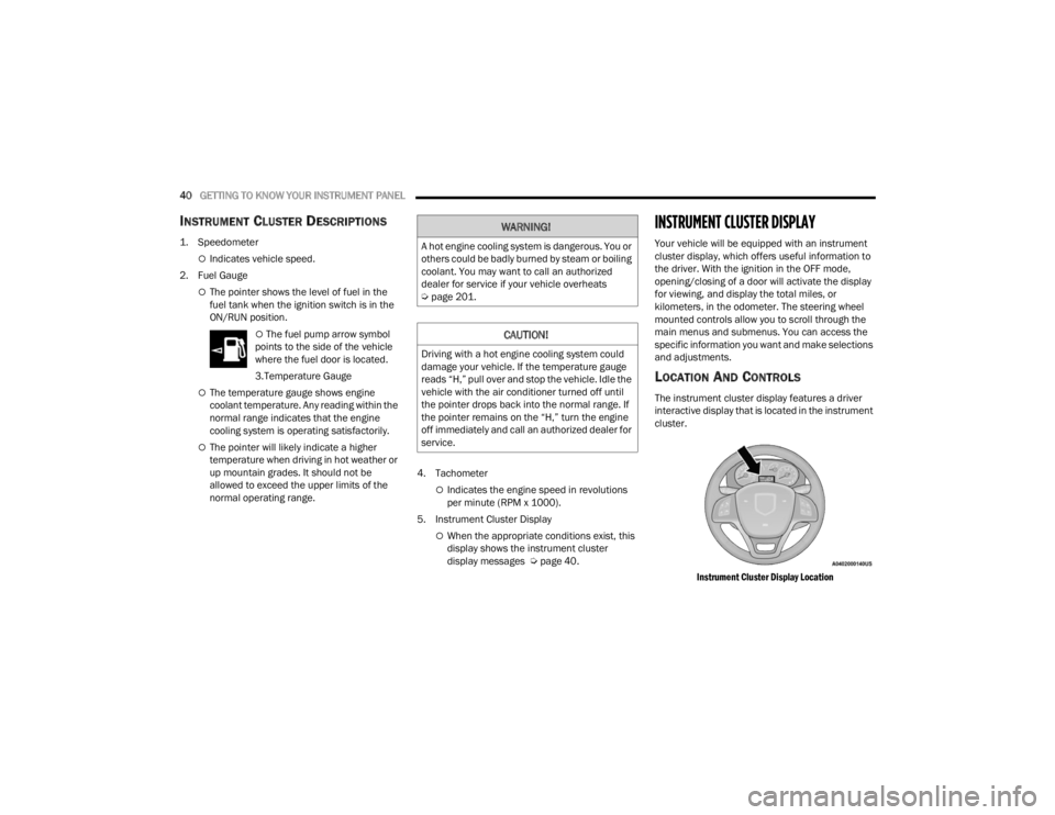
Your vehicle will be equipped with an instrument
cluster display, which offers useful information to
the driver. With the ignition in the OFF mode,
opening/closing of a door will activate the display
for viewing, and display the total miles, or
kilometers, in the odometer. The steering wheel
mounted controls allow you to scroll through the
main menus and submenus. You can access the
specific information you want and make selections
and adjustments.
LOCATION AND CONTROLS
The instrument cluster display features a driver
interactive display that is located in the instrument
cluster.
Instrument Cluster Display Location
WARNING!
A hot engine cooling system is dangerous. You or
others could be badly burned by steam or boiling
coolant. You may want to call an authorized
dealer for service if your vehicle overheats
Úpage 201.
CAUTION!
Driving with a hot engine cooling system could
damage your vehicle. If the temperature gauge
reads “H,” pull over and stop the vehicle. Idle the
vehicle with the air conditioner turned off until
the pointer drops back into the normal range. If
the pointer remains on the “H,” turn the engine
off immediately and call an authorized dealer for
service.
22_VM_OM_EN_USC_t.book Page 40
Page 43 of 260
GETTING TO KNOW YOUR INSTRUMENT PANEL41
The menu items described below are an example
of what can be found in the vehicle's menu:
Dimmer
Speed Beep
Trip A / B (options are selectable through the
steering wheel stalk)
Buzzer Volume
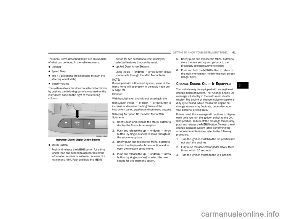
The system allows the driver to select information
by pushing the following buttons mounted on the
instrument panel to the right of the steering
column:
Instrument Cluster Display Control Buttons
MENU Button
Push and release the MENU button for a time
longer than one second to access/select the
information screens or submenu screens of a
main menu item. Push and hold the MENU button for two seconds to reset displayed/
selected features that can be reset.
Up And Down Arrow Buttons:
Using the up or down arrow button allows
you to cycle through the Main Menu Items.
NOTE:If equipped with a Uconnect system, some of the
menu items will be present in the radio head unit
Ú page 79.
Dimmer:
With headlights on and without entering in the
menu, push the up or down arrow button to
increase or decrease the brightness of the
instrument panel, graphics and command buttons.
Selecting An Option Of The Main Menu With
Submenu:
1. Briefly push and release the
MENU
button to
display the first submenu option.
2. Push and release the up or down arrow
button (by single pushes) to scroll through all
the submenu options.
3. Briefly push and release the MENU button to
select the displayed submenu option and to
open the relevant setup menu.
4. Push and release the up or down arrow
button (by single pushes) to select the new
setting for this submenu option. 5. Briefly push and release the MENU
button to
store the new setting and go back to the
previously selected submenu option.
6. Push and hold the MENU button to return to
the main menu (short hold) or the main screen
(longer hold).CHANGE ENGINE OIL — IF EQUIPPED
Your vehicle may be equipped with an engine oil
change indicator system. The “Change Engine Oil”
message will display in the instrument cluster
display. The engine oil change indicator system is
duty cycle based, which means the engine oil
change interval may fluctuate, dependent upon
your personal driving style.
Unless reset, this message will continue to display
each time you turn the ignition switch to the ON/
RUN position. To turn off the message temporarily,
push and release the MENU button. To reset the oil
change indicator system (after performing the
scheduled maintenance), refer to the following
procedure.
1. Turn the ignition switch to the ON position (do not start the engine).
2. Fully push the accelerator pedal slowly, three times, within 10 seconds.
3. Turn the ignition switch to the OFF position.
3
22_VM_OM_EN_USC_t.book Page 41