engine RENAULT ALASKAN 2017 Owner's Manual
[x] Cancel search | Manufacturer: RENAULT, Model Year: 2017, Model line: ALASKAN, Model: RENAULT ALASKAN 2017Pages: 340, PDF Size: 6.93 MB
Page 86 of 340
22. Shipping Mode On Push Storage
Fuse warning (where fitted)
This warning may appear if the extended storage
fuse switch is not pushed in (switched on). When
this warning appears, push in (switch on) the ex- tended storage fuse switch to turn off the warning.
For more information, see “Fuses” in the “8. Main-
tenance and do-it-yourself” section.
23. Headlight System Error warning
(where fitted)
This warning appears if the LED headlights are mal-
functioning. Have the system checked by an ap-
proved dealer or qualified workshop.
24. Reminder Turn OFF Headlights
warning
This warning appears when the driver side door is
opened with the headlight switch is left ONand the
ignition switch is placed in the OFF,ACCorLOCK
position. Place the headlight switch in the
formation, see “Headlight and turn signal switch” in
the “2. Instruments and controls” section.
25. Time for adriver break? indicator
This indicator appears when the set [Timer] alarm activates. You can set the time for up to 6hours.
(See “Settings” earlier in this section.) 26. Cruise control indicator
(where fitted)
This indicator shows the cruise control system sta-
tus. The status is shown by the colour.
See “Cruise control (where fitted)” in the “5. Start-
ing and driving” section for details.
27. Automatic Transmission (AT)
position indicator (AT models)
This indicator shows the automatic shift position.
In the manual shift mode, when the transmission
does not shift to the selected gear due to
atrans-
mission protection mode, the AT position indicator
will blink and achime will sound.
For further details, see “Driving with Automatic
Transmission (AT)” in the “5. Starting and driving”
section.
28. Automatic Transmission (AT) Error
warning (AT models)
If the Automatic Transmission (AT) Error warning
appears while the engine is running, or while driv-
ing, it may indicate that the AT is not functioning
properly and may need servicing. Have the system
checked, and if necessary repaired, by an approved
dealer or qualified workshop promptly. 29. Automatic Transmission (AT) park
warning (AT models)
This warning indicates that the Automatic Transmis-
sion (AT) parking function is not engaged. If the
transfer control is not secured in any driving position
while the AT shift lever is in the
P(Park) position, the
transmission will disengage and the wheels will not
lock.
For 4WD model: If the ATP warning appears with
the shift lever in the P(Park) position, shift the
Four-Wheel Drive (4WD) mode switch to the
<2WD>, <4H> or <4LO> position again with the
shift lever in the N(Neutral) position. (See “Four-
Wheel Drive (4WD) (where fitted)” in the “5. Start-
ing and driving” section.) WARNING
If the 4WD mode indicator (see “4WD mode
indicator” in the “5. Starting and driving” section)
is OFF or the ATP warning light is ON, this indi-
cates that the automatic transmission P(Park)
position will not function and could result in the
vehicle moving unexpectedly, causing serious
personal injury or property damage. Always set
the parking brake.
30. Parking Sensor Error warning
(where fitted)
This warning appears when the parking sensor (so-
nar) system is not functioning properly. If the warn-
ing appears, have the system checked by an ap-
proved dealer or qualified workshop.
2-28 Instruments and controls
Page 87 of 340
31. Low fuel level warning
The low fuel level warning appears on the vehicle
information display when the fuel level in the tank is
getting low. Refuel as soon as it is convenient, pref-
erably before the gauge reads the empty position.
For further details, see “Fuel gauge” earlier in this
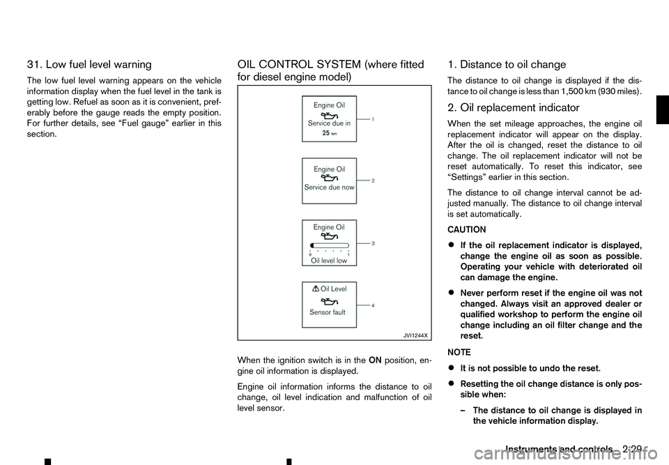
section. OIL CONTROL SYSTEM (where fitted
for diesel engine model)
When the ignition switch is in the
ONposition, en-
gine oil information is displayed.
Engine oil information informs the distance to oil
change, oil level indication and malfunction of oil
level sensor. 1. Distance to oil change
The distance to oil change is displayed if the dis-
tance to oil change is less than 1,500 km (930 miles).
2. Oil replacement indicator
When the set mileage approaches, the engine oil
replacement indicator will appear on the display.
After the oil is changed, reset the distance to oil
change. The oil replacement indicator will not be
reset automatically. To reset this indicator, see
“Settings” earlier in this section.
The distance to oil change interval cannot be ad-
justed manually. The distance to oil change interval
is set automatically.
CAUTION
•
If the oil replacement indicator is displayed,
change the engine oil as soon as possible.
Operating your vehicle with deteriorated oil
can damage the engine.
• Never perform reset if the engine oil was not
changed. Always visit an approved dealer or
qualified workshop to perform the engine oil
change including an oil filter change and the
reset.
NOTE
• It is not possible to undo the reset.
• Resetting the oil change distance is only pos-
sible when:
–T
he distance to oil change is displayed in
the vehicle information display. JVI1244X
Instruments and controls
2-29
Page 88 of 340
–T
he oil replacement indicator is displayed
in the vehicle information display.
• The engine oil should be changed before the
distance to oil change reaches
0km(0miles).
Continued driving after the distance to oil
change reaches 0km(0miles) may result in
reduced engine performance.
• The Diesel Particulate Filter (DPF) may also
become saturated because regeneration is
restricted once the distance to oil change
reaches 0km(0m iles).
Have the vehicle inspected by an approved
dealer or qualified workshop if the above con-
dition occurs.
• The oil change interval will reduce faster with
certain types of driving, especially at low
speeds in urban conditions.
3. Low level reminder
If the low level indicator is displayed, the engine oil level is low. If the low level reminder is displayed,
check the level using the engine oil dipstick. (See
“Checking engine oil level” in the “8. Maintenance
and do-it-yourself” section.)
CAUTION
The oil level should be checked regularly using
the engine oil dipstick. Operating with an insuffi-
cient amount of oil can damage the engine and
such damage is not covered by the warranty. 4. Oil level sensor warning
If the oil sensor warning is displayed, the engine oil
level sensor may be malfunctioning. Contact an ap-
proved dealer or qualified workshop immediately.
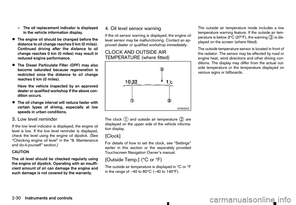
CLOCK AND OUTSIDE AIR
TEMPERATURE (where fitted)
The clock
➀and outside air temperature
➁are
displayed on the upper side of the vehicle informa-
tion display.
[Clock]
For details of how to set the clock, see “Settings”
earlier in this section or the separately provided
Touchscreen Navigation Owner’s manual.
[Outside Temp.] (°C or °F)
The outside air temperature is displayed in °C or °F
in the range of −40 to 60°C (−40 to 140°F). The outside air temperature mode includes
alow
temperature warning feature. If the outside air tem-
perature is below 3°C (37°F), the warning ➂is dis-
played on the screen (where fitted).
The outside temperature sensor is located in front of
the radiator. The sensor may be affected by road or
engine heat, wind directions and other driving con-
ditions. The display may differ from the actual out-
side temperature or the temperature displayed on
various signs or billboards. JVI0932XZ
2-30 Instruments and controls
Page 89 of 340
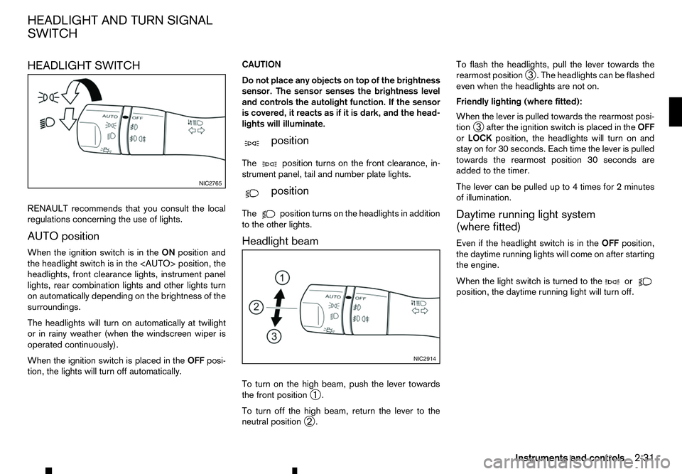
HEADLIGHT SWITCH
RENAULT recommends that you consult the local
regulations concerning the use of lights.
AUTO position
When the ignition switch is in the ONposition and
the headlight switch is in the
headlights, front clearance lights, instrument panel
lights, rear combination lights and other lights turn
on automatically depending on the brightness of the
surroundings.
The headlights will turn on automatically at twilight
or in rainy weather (when the windscreen wiper is
operated continuously).
When the ignition switch is placed in the OFFposi-
tion, the lights will turn off automatically. CAUTION
Do not place any objects on top of the brightness
sensor. The sensor senses the brightness level
and controls the autolight function. If the sensor
is covered, it reacts as if it is dark, and the head-
lights will illuminate.
m position
The position
turns on the front clearance, in-
strument panel, tail and number plate lights.
m position
The position
turns on the headlights in addition
to the other lights.
Headlight beam
To turn on the high beam, push the lever towards
the front position ➀.
To turn off the high beam, return the lever to the
neutral position ➁. To flash the headlights, pull the lever towards the
rearmost position
➂.T
he headlights can be flashed
even when the headlights are not on.
Friendly lighting (where fitted):
When the lever is pulled towards the rearmost posi-
tion ➂after the ignition switch is placed in the
OFF
or LOCK position, the headlights will turn on and
stay on for 30 seconds. Each time the lever is pulled
towards the rearmost position 30 seconds are
added to the timer.
The lever can be pulled up to 4times for 2minutes
of illumination.
Daytime running light system
(where fitted)
Even if the headlight switch is in the OFFposition,
the daytime running lights will come on after starting
the engine.
When the light switch is turned to the or
position, the daytime running light will turn off.NIC2765
NIC2914
HEADLIGHT AND TURN SIGNAL
SWITCH
Instruments and controls2-31
Page 90 of 340
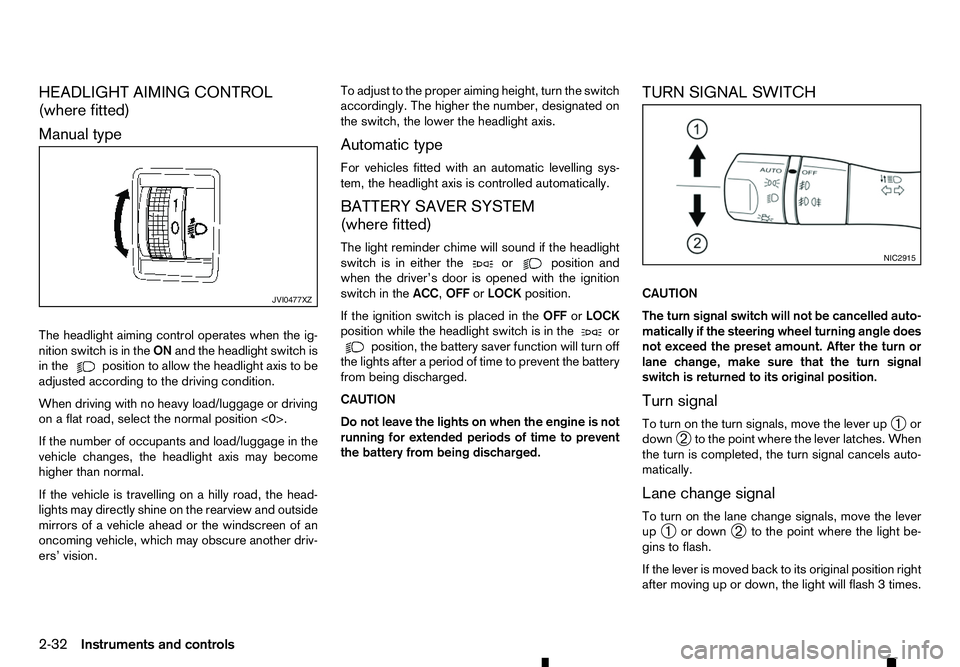
HEADLIGHT AIMING CONTROL
(where fitted)
Manual type
The headlight aiming control operates when the ig- nition switch is in the ONand the headlight switch is
in the position to allow the headlight axis to be
adjusted according to the driving condition.
When driving with no heavy load/luggage or driving
on aflat road, select the normal position <0>.
If the number of occupants and load/luggage in the
vehicle changes, the headlight axis may become
higher than normal.
If the vehicle is travelling on ahilly road, the head-
lights may directly shine on the rearview and outside mirrors of avehicle ahead or the windscreen of an
oncoming vehicle, which may obscure another driv-
ers’ vision. To adjust to the proper aiming height, turn the switch
accordingly. The higher the number, designated on
the switch, the lower the headlight axis.
Automatic type
For vehicles fitted with an automatic levelling sys-
tem, the headlight axis is controlled automatically.
BATTERY SAVER SYSTEM
(where fitted)
The light reminder chime will sound if the headlight
switch is in either the or position and
when the driver’s door is opened with the ignition
switch in the ACC,OFForLOCK position.
If the ignition switch is placed in the OFForLOCK
position while the headlight switch is in the or
position, the battery saver function will turn off
the lights after aperiod of time to prevent the battery
from being discharged.
CAUTION
Do not leave the lights on when the engine is not
running for extended periods of time to prevent
the battery from being discharged. TURN SIGNAL SWITCH
CAUTION
The turn signal switch will not be cancelled auto-
matically if the steering wheel turning angle does
not exceed the preset amount. After the turn or
lane change, make sure that the turn signal
switch is returned to its original position.
Turn signal
To turn on the turn signals, move the lever up
➀or
down ➁to the point where the lever latches. When
the turn is completed, the turn signal cancels auto-
matically.
Lane change signal
To turn on the lane change signals, move the lever
up ➀ or down
➁to the point where the light be-
gins to flash.
If the lever is moved back to its original position right
after moving up or down, the light will flash 3times. JVI0477XZ NIC2915
2-32 Instruments and controls
Page 93 of 340
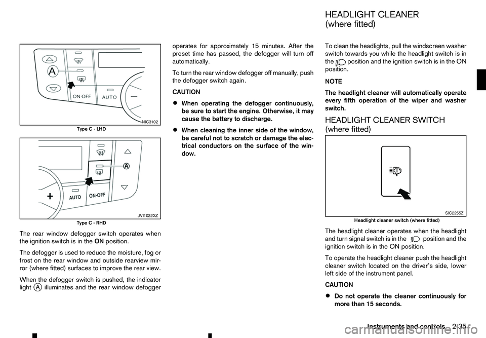
The rear window defogger switch operates when
the ignition switch is in the ONposition.
The defogger is used to reduce the moisture, fog or
frost on the rear window and outside rearview mir-
ror (where fitted) surfaces to improve the rear view.
When the defogger switch is pushed, the indicator
light j
Ai lluminates and the rear window defogger operates for approximately 15 minutes. After the
preset time has passed, the defogger will turn off
automatically.
To turn the rear window defogger off manually, push
the defogger switch again.
CAUTION
• When operating the defogger continuously,
be sure to start the engine. Otherwise, it may
cause the battery to discharge.
• When cleaning the inner side of the window,
be careful not to scratch or damage the elec-
trical conductors on the surface of the win-
dow. To clean the headlights, pull the windscreen washer
switch towards you while the headlight switch is in
the position and the ignition switch is in the ON
position.
NOTE
The headlight cleaner will automatically operate
every fifth operation of the wiper and washer
switch.
HEADLIGHT CLEANER SWITCH
(where fitted)
The headlight cleaner operates when the headlight
and turn signal switch is in the position and the
ignition switch is in the ON position.
To operate the headlight cleaner push the headlight
cleaner switch located on the driver’s side, lower
left side of the instrument panel.
CAUTION
• Do not operate the cleaner continuously for
more than 15 seconds. NIC3102
Type C-LHD JVI1022XZ
Type C-RHD SIC2255Z
Headlight cleaner switch (where fitted)
HEADLIGHT CLEANER
(where fitted)
Instruments and controls 2-35
Page 96 of 340
If the window does not close
automatically
If the power window automatic function (closing
only) does not operate properly, perform the follow-
ing procedure to initialise the power window sys-
tem.
1. With the engine running.
2. Close the door.
3. Open the window completely by operating the power window switch.
4. Pull the power window switch and hold it to close the window, and then hold the switch more than
3seconds after the window is closed completely.
5. Release the power window switch. Operate the window by the automatic function to confirm the
initialisation is complete.
If the power window automatic function does not
operate properly after performing the procedure above, have your vehicle checked by an approved
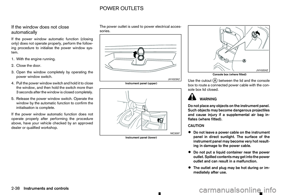
dealer or qualified workshop. The power outlet is used to power electrical acces-
sories.
Use the cutoutj
Ab etween the lid and the console
box to route aconnected power cable with the con-
sole box lid closed. WARNING
Do not place any objects on the instrument panel.
Such objects may become dangerous projectiles
and cause injury if asupplemental air bag in-
flates (where fitted).
CAUTION
• Do not leave
apower cable on the instrument
panel in direct sunlight. The surface of the
instrument panel may become very hot result-
ing in damage to the power cable.
• Do not put
aliquid container near the power
outlet. Spilled contents may get into the power
outlet and can result in amalfunction.
• The outlet and plug may be hot during or im-
mediately after use. JVI1023XZ
Instrument panel (upper)
NIC3097
Instrument panel (lower) JVI1025XZ
Console box (where fitted)
POWER OUTLETS
2-38 Instruments and controls
Page 97 of 340
•
This power outlet is not designed for use with
ac igarette lighter unit.
• Do not use accessories that exceed
acom-
bined power draw of 12 volt, 120W (10A)
• Do not use double adapters or more than one
electrical accessory.
• Use this power outlet with the engine running
to avoid discharging the vehicle battery.
• Avoid using when the air conditioner, head-
lights or rear window defogger is on (where
fitted).
• Push the plug in as far as it will go. If good
contact is not made, the plug may overheat or the internal temperature fuse may blow.
• Before inserting or disconnecting
aplug, be
sure that the electrical accessory being used
is turned OFF.
• When not in use, be sure to close the cap. Do
not allow water or any liquid to contact the
outlet. WARNING
• The storage compartments should not be
used while driving so that the full attention
may be given to vehicle operation.
• Keep the storage lids closed while driving to
help prevent injury in an accident or
asudden
stop.
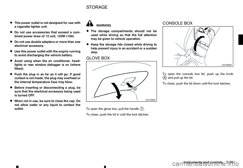
GLOVE BOX
To open the glove box, pull the handle ➀.
To close, push the lid in until the lock latches. CONSOLE BOX
To open the console box lid, push up the knob
j
Aa nd pull up the lid.
To close, push the lid down until the lock latches. JVI1 102XZ JVI1026XZ
STORAGE
Instruments and controls
2-39
Page 101 of 340
If the sunroof does not operate properly after per-
forming the procedure above, have your vehicle
checked by an approved dealer or qualified work-
shop. CAUTION
• Turn off the lights when you leave the vehicle.
• Do not use the lights for extended periods of
time with the engine stopped. This could re-
sult in
adischarged battery.
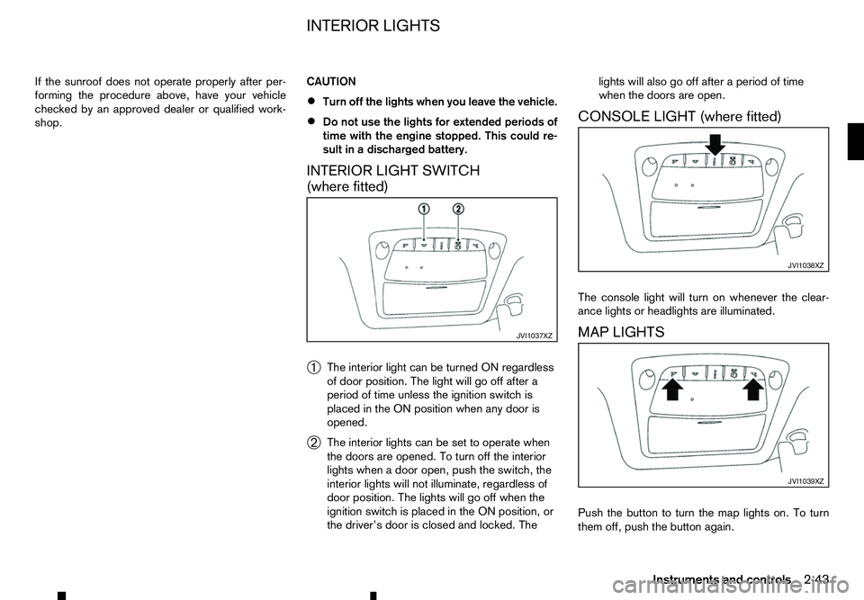
INTERIOR LIGHT SWITCH
(where fitted)
➀ The interior light can be turned ON regardless
of door position. The light will go off after a
period of time unless the ignition switch is
placed in the ON position when any door is
opened.
➁ The interior lights can be set to operate when
the doors are opened. To turn off the interior
lights when
adoor open, push the switch, the
interior lights will not illuminate, regardless of
door position. The lights will go off when the
ignition switch is placed in the ON position, or
the driver’s door is closed and locked. The lights will also go off after
aperiod of time
when the doors are open.
CONSOLE LIGHT (where fitted)
The console light will turn on whenever the clear-
ance lights or headlights are illuminated.
MAP LIGHTS
Push the button to turn the map lights on. To turn
them off, push the button again. JVI1037XZ JVI1038XZ
JVI1039XZ
INTERIOR LIGHTS
Instruments and controls2-43
Page 116 of 340
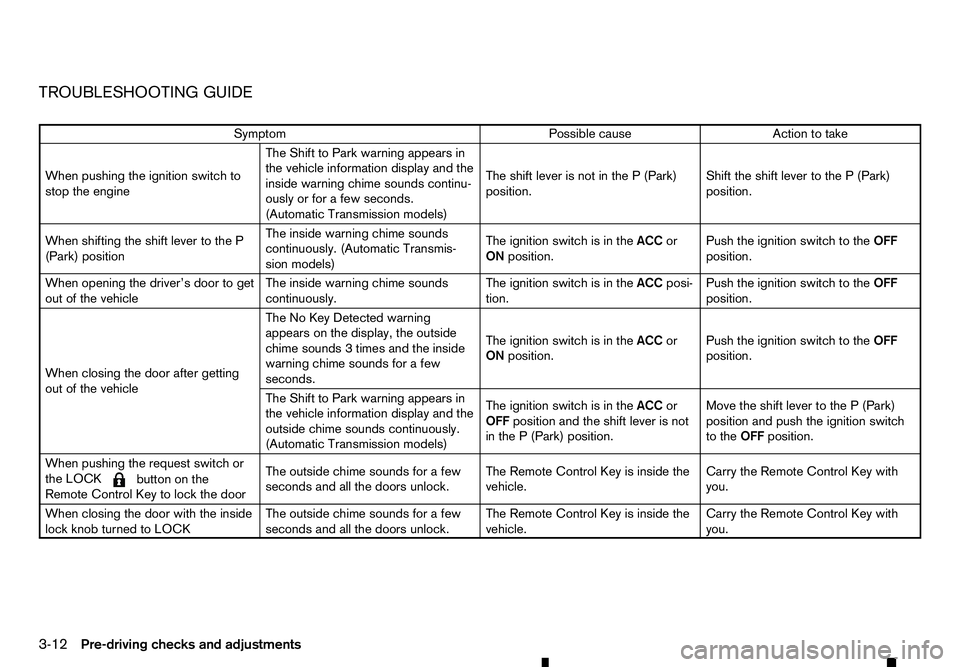
TROUBLESHOOTING GUIDE
Symptom
Possible cause
Action to take
When pushing the ignition switch to
stop the engine The Shift to Park warning appears in
the vehicle information display and the
inside warning chime sounds continu-
ously or for
afew seconds.
(Automatic Transmission models) The shift lever is not in the
P(Park)
position. Shift the shift lever to the
P(Park)
position.
When shifting the shift lever to the P
(Park) position The inside warning chime sounds
continuously. (Automatic Transmis-
sion models)
The ignition switch is in the
ACCor
ON position. Push the ignition switch to the
OFF
position.
When opening the driver’s door to get
out of the vehicle The inside warning chime sounds
continuously.The ignition switch is in the
ACCposi-
tion. Push the ignition switch to the
OFF
position.
When closing the door after getting
out of the vehicle The No Key Detected warning
appears on the display, the outside
chime sounds
3times and the inside
warning chime sounds for afew
seconds. The ignition switch is in the
ACCor
ON position. Push the ignition switch to the
OFF
position.
The Shift to Park warning appears in
the vehicle information display and the
outside chime sounds continuously.
(Automatic Transmission models) The ignition switch is in the
ACCor
OFF position and the shift lever is not
in the P(Park) position. Move the shift lever to the
P(Park)
position and push the ignition switch
to the OFFposition.
When pushing the request switch or
the LOCK
m button
on the
Remote Control Key to lock the door The outside chime sounds for
afew
seconds and all the doors unlock. The Remote Control Key is inside the
vehicle. Carry the Remote Control Key with
you.
When closing the door with the inside
lock knob turned to LOCK The outside chime sounds for
afew
seconds and all the doors unlock. The Remote Control Key is inside the
vehicle. Carry the Remote Control Key with
you.
3-12 Pre-driving checks and adjustments