buttons RENAULT ALASKAN 2017 Owners Manual
[x] Cancel search | Manufacturer: RENAULT, Model Year: 2017, Model line: ALASKAN, Model: RENAULT ALASKAN 2017Pages: 340, PDF Size: 6.93 MB
Page 3 of 340
NOTE
Indicates additional helpful information.
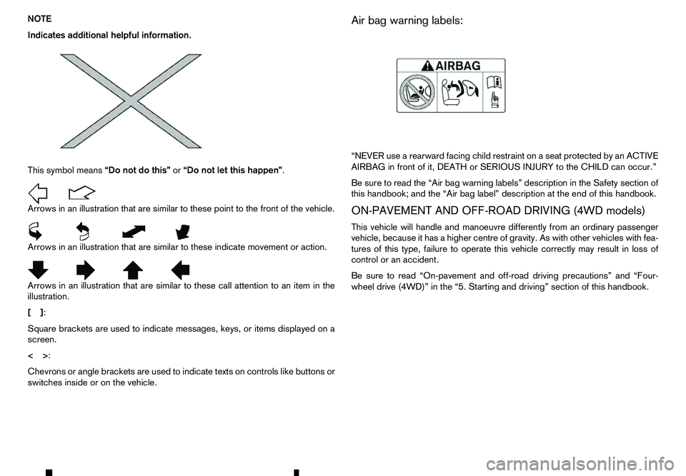
This symbol means “Do not do this”or“Do not let this happen”.
Arrows in an illustration that are similar to these point to the front of the vehicle.
Arrows in an illustration that are similar to these indicate movement or action.
Arrows in an illustration that are similar to these call attention to an item in the
illustration.
[] :
Square brackets are used to indicate messages, keys, or items displayed on a
screen.
<> :
Chevrons or angle brackets are used to indicate texts on controls like buttons or
switches inside or on the vehicle. Air bag warning labels:
“NEVER use
arearward facing child restraint on aseat protected by an ACTIVE
AIRBAG in front of it, DEATH or SERIOUS INJURY to the CHILD can occur.”
Be sure to read the “Air bag warning labels” description in the Safety section of
this handbook; and the “Air bag label” description at the end of this handbook.
ON-PAVEMENT AND OFF-ROAD DRIVING (4WD models)
This vehicle will handle and manoeuvre differently from an ordinary passenger
vehicle, because it has ahigher centre of gravity. As with other vehicles with fea-
tures of this type, failure to operate this vehicle correctly may result in loss of
control or an accident.
Be sure to read “On-pavement and off-road driving precautions” and “Four- wheel drive (4WD)” in the “5. Starting and driving” section of this handbook.
Page 73 of 340
•
Remote Control Key system (where fitted)
—“ Push-button ignition switch (models with Re-
mote Control Key system)” in the “5. Starting
and driving” section
• Oil control system (where fitted)
—“
Oil control system (where fitted for diesel
engine model)” later in this section
• Tyre Pressure information (where fitted)
—“
Tyre Pressure Monitoring System (TPMS)
(where fitted)” in the “5. Starting and driving”
section HOW TO USE THE VEHICLE
INFORMATION DISPLAY
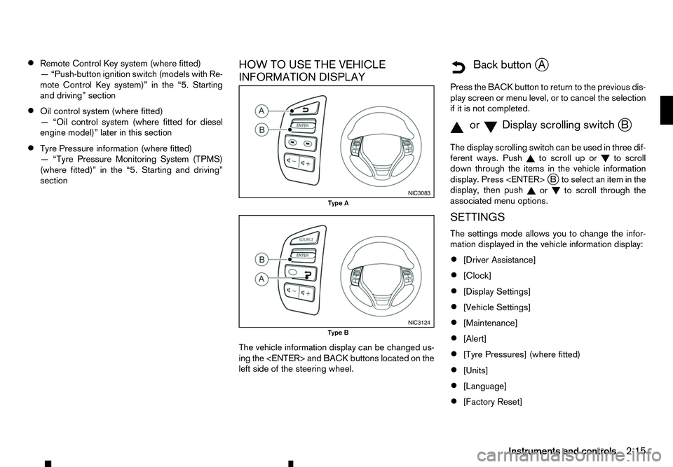
The vehicle information display can be changed us-
ing the
left side of the steering wheel.
m Back
button
jA
Press the BACK button to return to the previous dis-
play screen or menu level, or to cancel the selection if it is not completed.
m orm Display
scrolling switch
jB
The display scrolling switch can be used in three dif-
ferent ways. Push to scroll up or
to scroll
down through the items in the vehicle information
display. Press
display, then push or to scroll through the
associated menu options.
SETTINGS
The settings mode allows you to change the infor-
mation displayed in the vehicle information display:
• [Driver Assistance]
• [Clock]
• [Display Settings]
• [Vehicle Settings]
• [Maintenance]
• [Alert]
• [Tyre Pressures] (where fitted)
• [Units]
• [Language]
• [Factory Reset] NIC3083
Type A
NIC3124
Type B
Instruments and controls2-15
Page 77 of 340
![RENAULT ALASKAN 2017 Owners Manual [Tyre Pressures] (where fitted)
The settings in the Tyre pressures] menu are all
related to the Tyre pressure monitoring system
TPMS (where fitted) (see “Tyre Pressure Monitor-
ing System (TPMS) (wh RENAULT ALASKAN 2017 Owners Manual [Tyre Pressures] (where fitted)
The settings in the Tyre pressures] menu are all
related to the Tyre pressure monitoring system
TPMS (where fitted) (see “Tyre Pressure Monitor-
ing System (TPMS) (wh](/img/7/58394/w960_58394-76.png)
[Tyre Pressures] (where fitted)
The settings in the Tyre pressures] menu are all
related to the Tyre pressure monitoring system
TPMS (where fitted) (see “Tyre Pressure Monitor-
ing System (TPMS) (where fitted)” in the “5. Start-
ing and driving” section).
• [Target Front]
• [Target Rear]
• [Tyre Pressure Unit]
• [Calibrate]
[Target Front]:
The [Target Front] tyre pressure is the pressure specified for the front tyres on the tyre placard (see
“Tyre placard” in the “9. Technical information” sec-
tion and “Tyre Pressure Monitoring System (TPMS)
(where fitted)” in the “5. Starting and driving” sec-
tion).
Use the or and the
and change the value for the [Target Front] tyre
pressure.
[Target Rear]:
The [Target Rear] tyre pressure is the pressure
specified for the rear tyres on the tyre placard (see
“Tyre placard” in the “9. Technical information” sec-
tion and “Tyre Pressure Monitoring System (TPMS)
(where fitted)” in the “5. Starting and driving” sec- tion). Use the or and the
and change the value for the [Target Rear] tyre pres-
sure.
[Tyre Pressure Unit]:
The unit for tyre pressure that displays in the vehicle
information display can be changed to:
• psi
• bar
• kPa
• Kgf/cm
2
Use the or and
the
and change the unit. Pressure units conversion table kPa psi bar kgf/cm
2
200 29 2.0 2.0
210 30 2.1 2.1
220 32 2.2 2.2
230 33 2.3 2.3
240 35 2.4 2.4
250 36 2.5 2.5
250 36 2.5 2.5
260 38 2.6 2.6
270 39 2.7 2.7
280 41 2.8 2.8
290 42 2.9 2.9
300 44 3.0 3.0
310 45 3.1 3.1
320 46 3.2 3.2
330 48 3.3 3.3
340 49 3.4 3.4
[Calibrate]:
The tyre pressure is affected by the temperature of
the tyre; the tyre temperature increases when the
vehicle is driven. The TPMS system uses tempera-
ture sensors in the tyres to compensate for changes
in temperature in order to prevent false TPMS warn-
ings.
The [CALIBRATE] function resets the previously
stored temperature value. It is recommended that
this function is performed after the tyre pressures
are adjusted.
Instruments and controls 2-19
Page 78 of 340
See “Tyre Pressure Monitoring System (TPMS)
(where fitted)” in the “5. Starting and driving” sec-
tion.
Use the or and the
or cancel the calibration process. While the calibra-
tion process is active, the message: [Resetting tyre
pressure system] will be displayed.
[Units]
The following items are available under the [Units]
menu.
• [Distance/Fuel]
• [Tyre Pressures] (where fitted)
• [Temperature]
[Distance/Fuel]:
The unit for the distance and fuel consumption that
displays in the vehicle information display can be
changed to:
• [km, l/100km]
• [km, km/l]
• [miles, MPG]
[Tyre Pressures] (where fitted):
The unit for tyre pressure that displays in the vehicle
information display can be changed to:
• psi
• bar
• kPa •
Kgf/cm
2
Use the or and
the
and change the unit.
[Temperature]:
The temperature that displays in the vehicle informa-
tion display can be changed from:
• °C (Celsius)
• °F (Fahrenheit)
[Language]
The language of the vehicle information display can
be changed to:
• English
• French
• German
• Italian
• Portuguese
• Dutch
• Spanish
• Turkish
• Russian
Use the or and the
and change the language of the vehicle information
display. [Factory Reset]
The settings in the vehicle information display can
be reset back to the factory default. To reset the
vehicle information display:
1. Use the or buttons to select [Settings], and
press the
2. Select [Factory Reset] using the or buttons
and press the
3. Select [Yes] to return all settings back to default by pressing the
To cancel the reset operation select [No] or press
the BACK button located on the left side of the
steering wheel.
2-20 Instruments and controls
Page 111 of 340
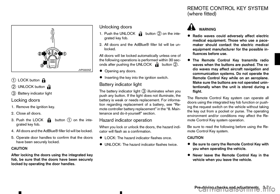
➀
LOCK button
➁
UNLOCK button
➂
Battery indicator light
Locking doors
1. Remove the ignition key.
2. Close all doors.
3. Push the LOCK button
➀on the inte-
grated key fob.
4. All doors and the AdBlue® filler lid will be locked.
5. Operate door handles to confirm that the doors have been securely locked.
CAUTION
After locking the doors using the integrated key
fob, be sure that the doors have been securely
locked by operating the door handles. Unlocking doors
1. Push the UNLOCK button
➁on the inte-
grated key fob.
2. All doors and the AdBlue® filler lid will be un- locked.
All doors will be locked automatically unless one of
the following operations is performed within 30 sec-
onds after pushing the UNLOCK button
➁.
• Opening any doors.
• Inserting the key into the ignition switch.
Battery indicator light
The battery indicator light ➂illuminates when you
push any button. If the light does not illuminate, the
battery is weak or needs replacement. For informa-
tion regarding replacement of abattery, see “Re-
mote controller battery replacement” in the “8. Main-
tenance and do-it-yourself” section.
Hazard indicator operation
When you lock or unlock the doors, the hazard indi-
cator will flash as aconfirmation.
• LOCK: The hazard indicator flashes once.
• UNLOCK: The hazard indicator flashes twice. WARNING
• Radio waves could adversely affect electric
medical equipment. Those who use apace-
maker should contact the electric medical
equipment manufacturer for the possible in-
fluences before use.
• The Remote Control Key transmits radio
waves when the buttons are pushed. The ra-
dio waves may affect aircraft navigation and
communication systems. Do not operate the
Remote Control Key while on an aeroplane.
Make sure the buttons are not operated unin-
tentionally when the unit is stored during a
flight.
The Remote Control Key system can operate all
doors using the integrated key fob function or push-
ing the request switch on the vehicle without taking
the key out from apocket or purse. The operating
environment and/or conditions may affect the Re-
mote Control Key system operation.
Be sure to read the following before using the Re-
mote Control Key system.
CAUTION
• Be sure to carry the Remote Control Key with
you when operating the vehicle.
• Never leave the Remote Control Key in the
vehicle when you leave the vehicle. JVP0222XZ
REMOTE CONTROL KEY SYSTEM
(where fitted)
Pre-driving checks and adjustments 3-7
Page 118 of 340
USING REMOTE KEYLESS ENTRY
SYSTEM
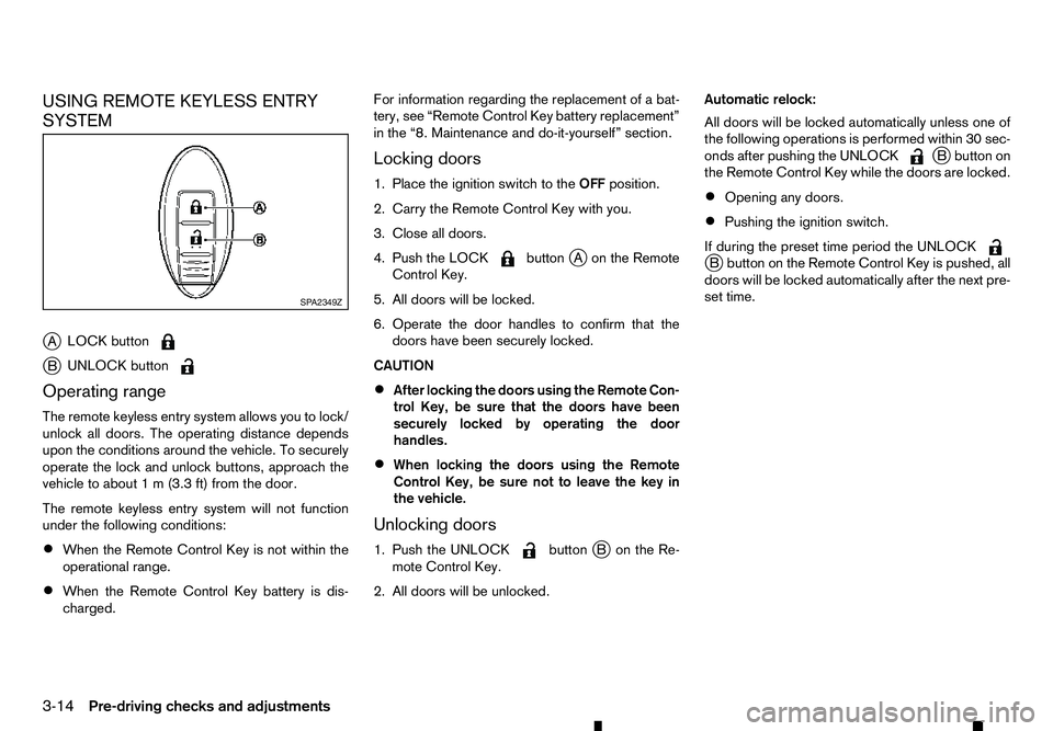
j A LOCK button j
B UNLOCK button
Operating range
The remote keyless entry system allows you to lock/
unlock all doors. The operating distance depends
upon the conditions around the vehicle. To securely
operate the lock and unlock buttons, approach the
vehicle to about 1m(3.3 ft) from the door.
The remote keyless entry system will not function
under the following conditions:
• When the Remote Control Key is not within the
operational range.
• When the Remote Control Key battery is dis-
charged. For information regarding the replacement of
abat-
tery, see “Remote Control Key battery replacement”
in the “8. Maintenance and do-it-yourself” section.
Locking doors
1. Place the ignition switch to the OFFposition.
2. Carry the Remote Control Key with you.
3. Close all doors.
4. Push the LOCK button
jAo nthe Remote
Control Key.
5. All doors will be locked.
6. Operate the door handles to confirm that the doors have been securely locked.
CAUTION
• After locking the doors using the Remote Con-
trol Key, be sure that the doors have been
securely locked by operating the door
handles.
• When locking the doors using the Remote
Control Key, be sure not to leave the key in
the vehicle.
Unlocking doors
1. Push the UNLOCK button
jBo nthe Re-
mote Control Key.
2. All doors will be unlocked. Automatic relock:
All doors will be locked automatically unless one of
the following operations is performed within 30 sec-
onds after pushing the UNLOCK j
Bb utton on
the Remote Control Key while the doors are locked.
• Opening any doors.
• Pushing the ignition switch.
If during the preset time period the UNLOCK j
Bb utton on the Remote Control Key is pushed, all
doors will be locked automatically after the next pre-
set time. SP A2349Z
3-14 Pre-driving checks and adjustments
Page 133 of 340

Phone control buttons ......................................... 4-58
Bluetooth® Hands-Free Phone System (without
navigation system and colour display)....................... 4-59 Bluetooth® mobile phone feature ........................ 4-59
Hands-free telephone control .............................. 4-61Steering wheel switches (where fitted)................ 4-64
Bluetooth® Hands-Free Phone System (with
navigation system) ................................................... 4-65 Regulatory information ........................................ 4-65 Control buttons and microphone ......................... 4-66
Pairing procedure ............................................... 4-66
Phonebook ......................................................... 4-67
Making
acall ...................................................... 4-67
Receiving acall................................................... 4-67
During acall ....................................................... 4-67
Ending acall ....................................................... 4-67
Bluetooth® settings ............................................ 4-67
Telephone setup ................................................. 4-68
Page 134 of 340

WARNING
• Do not adjust the heater and air conditioner
controls or audio controls while driving so that full attention may be given to vehicle opera-
tion.
• If you noticed any foreign objects entering the
system hardware, spilled liquid on the sys-
tem, or noticed smoke or fumes coming out
from the system, or any other unusual opera-
tion is observed, stop using the system imme-
diately and contact the nearest approved
dealer or qualified workshop. Ignoring such
conditions may lead to an accident, fire or electric shock.
• Do not disassemble or modify this system. If
you do, it may lead to an accident, fire, or
electric shock.
CAUTION
Do not use the system when the engine is not
running for extended periods of time to prevent
battery discharge.
1.Phone button (P. 4-65)
2. Power/VOL (volume) dial
3. Display screen (P. 4-3)
4.
5.
6. Audio control buttons 7.
8. For navigation system control buttons refer to
the separate Navigation System Owner’s
Manual.
9. Brightness control/display ON·OFF button
(P. 4-3)
10.
SAFETY PRECAUTIONS
CENTRE MULTI-FUNCTION CONTROL PANEL (models with navigation
system)
4-2 Display screen, heater and air conditioner, and audio system
Page 158 of 340
MANUAL AIR CONDITIONER AND
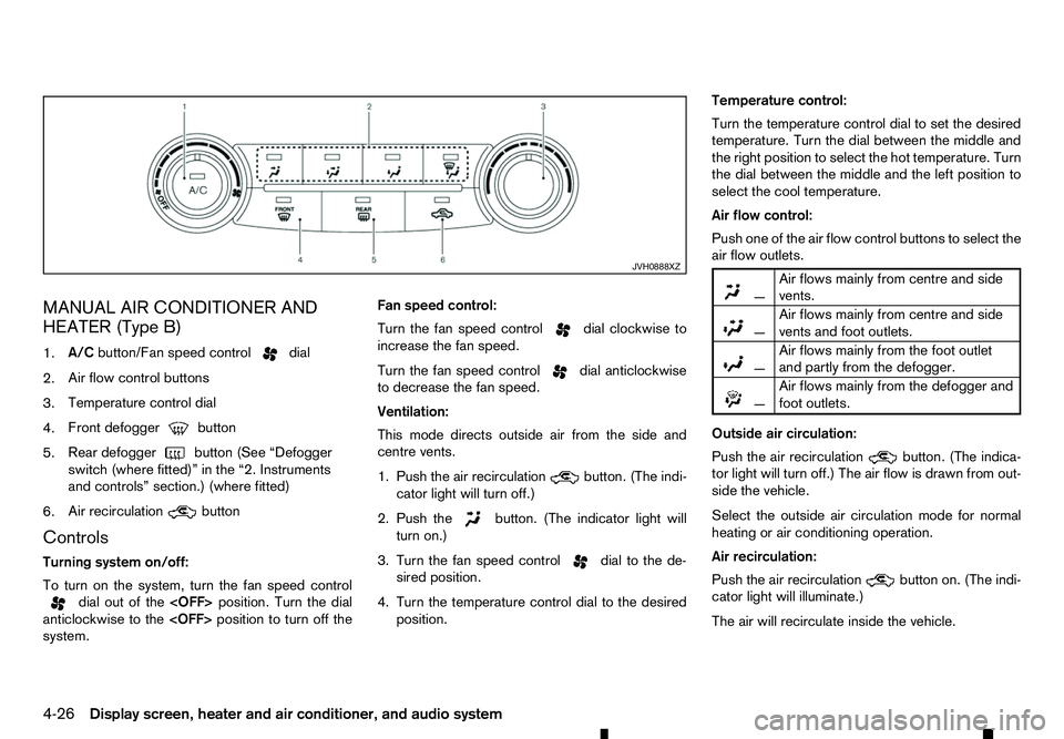
HEATER (Type B)
1. A/C
button/Fan speed control dial
2. Air flow control buttons
3. Temperature control dial
4. Front defogger button
5. Rear defogger
button (See “Defogger
switch (where fitted)” in the “2. Instruments
and controls” section.) (where fitted)
6. Air recirculation button
Controls
Turning system on/off:
To turn on the system, turn the fan speed control dial out of the
anticlockwise to the
system. Fan speed control:
Turn the fan speed control dial clockwise to
increase the fan speed.
Turn the fan speed control dial anticlockwise
to decrease the fan speed.
Ventilation:
This mode directs outside air from the side and
centre vents.
1. Push the air recirculation button. (The indi-
cator light will turn off.)
2. Push the button. (The indicator light will
turn on.)
3. Turn the fan speed control dial to the de-
sired position.
4. Turn the temperature control dial to the desired position. Temperature control:
Turn the temperature control dial to set the desired
temperature. Turn the dial between the middle and
the right position to select the hot temperature. Turn
the dial between the middle and the left position to
select the cool temperature.
Air flow control:
Push one of the air flow control buttons to select the
air flow outlets.
m
—
Air
flows mainly from centre and side
vents.
m —
Air
flows mainly from centre and side
vents and foot outlets.
m —
Air
flows mainly from the foot outlet
and partly from the defogger.
m —
Air
flows mainly from the defogger and
foot outlets.
Outside air circulation:
Push the air recirculation button. (The indica-
tor light will turn off.) The air flow is drawn from out-
side the vehicle.
Select the outside air circulation mode for normal
heating or air conditioning operation.
Air recirculation:
Push the air recirculation button on. (The indi-
cator light will illuminate.)
The air will recirculate inside the vehicle. JVH0888XZ
4-26 Display screen, heater and air conditioner, and audio system
Page 160 of 340
5. Turn the temperature control dial to the desired
position between the middle and the cool (left)
position.
Av isible mist may be seen coming from the vents in
hot, humid conditions as the air is cooled rapidly.
This does not indicate amalfunction.
• For quick cooling when the outside temperature
is high, push the air recirculation button.
(The indicator light will turn on.) Be sure to return
the air recirculation button to turn off for
normal cooling.
Dehumidified heating:
This mode is used to heat and dehumidify the air.
1. Push the air recirculation button. (The indi-
cator light will turn off.)
2. Push the button. (The indicator light will
turn on.)
3. Turn the fan speed control dial to the de-
sired position.
4. Push the A/Cbutton. (The indicator light will turn
on.)
5. Turn the temperature control dial to the desired position between the middle and the hot (right)
position. Dehumidified defogging:
This mode is used to defog the windows and dehu-
midify the air.
1. Push the front defogger button. (The indi-
cator lights on the front defogger button
and the
A/C button will turn on.) Then the air
recirculation indicator light will turn off.
2. Turn the fan speed control dial to the de-
sired position.
3. Turn the temperature control dial to the desired position.
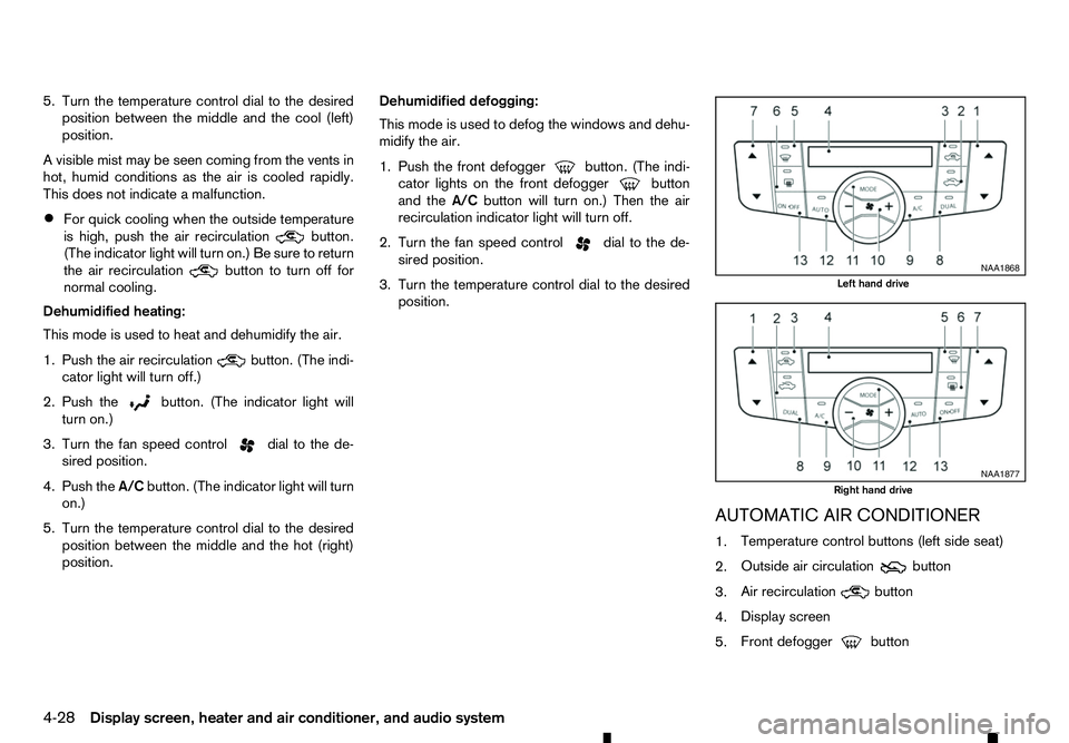
AUTOMATIC AIR CONDITIONER
1.Temperature control buttons (left side seat)
2. Outside air circulation button
3. Air recirculation
button
4. Display screen
5. Front defogger button NAA1868
Left hand drive
NAA1877
Right hand drive
4-28 Display screen, heater and air conditioner, and audio system