change wheel RENAULT ALASKAN 2017 Owners Manual
[x] Cancel search | Manufacturer: RENAULT, Model Year: 2017, Model line: ALASKAN, Model: RENAULT ALASKAN 2017Pages: 340, PDF Size: 6.93 MB
Page 54 of 340
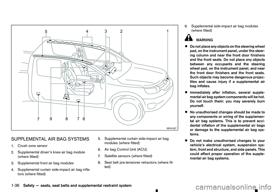
SUPPLEMENTAL AIR BAG SYSTEMS
1. Crush zone sensor
2. Supplemental driver’s knee air bag module
(where fitted)
3. Supplemental front air bag modules
4. Supplemental curtain side-impact air bag infla-
tors (where fitted) 5.
Supplemental curtain side-impact air bag
modules (where fitted)
6. Air bag Control Unit (ACU)
7. Satellite sensors (where fitted)
8. Seat belt pre-tensioner retractors (where fit-
ted) 9.
Supplemental side-impact air bag modules
(where fitted) WARNING
• Do not place any objects on the steering wheel
pad, on the instrument panel, under the steer-
ing column and near the front door finishers
and the front seats. Do not place any objects
between any occupants and the steering
wheel pad, on the instrument panel, and near
the front door finishers and the front seats.
Such objects may become dangerous projec-
tiles and cause injury if asupplemental air
bag inflates.
• Immediately after inflation, several supple-
mental air bag system components will be hot.
Do not touch them: you may severely burn
yourself.
• No unauthorised changes should be made to
any components or wiring of the supplemen-
tal air bag systems. This is to prevent acci-
dental inflation of the supplemental air bags
or damage to the supplemental air bag sys-
tems.
• Do not make unauthorised changes to your
vehicle’s electrical system, suspension sys-
tem, front end structure, and side panels. This
could affect proper operation of the supple-
mental air bag systems. NP A1527
1-36 Safety —seats, seat belts and supplemental restraint system
Page 55 of 340
•
Tampering with the supplemental air bag sys-
tems may result in serious personal injury.
Tampering includes changes to the steering
wheel and the instrument panel by placing
materials over the steering wheel pad and
above, around or on the instrument panel or
by installing additional trim materials around
the supplemental air bag systems.
• Work on and around the supplemental air bag
systems should be done by an approved
dealer or qualified workshop. The SRS wiring
should not be modified or disconnected. Un-
authorised electrical test equipment and
probing devices should not be used on the
supplemental air bag systems.
• The SRS wiring harness connectors are yel-
low for easy identification.
• Never install
arear-facing child restraint sys-
tem on the front passenger seat without first
deactivating the passenger air bag with the
front passenger air bag switch. In afrontal
collision, supplemental front-impact air bags
inflate with great force. An inflating supple-
mental front-impact air bag could seriously
injure or kill your child.
When the air bags inflate, afairly loud noise may be
heard, followed by the release of smoke. This smoke
is not harmful and does not indicate afire. Care
should be taken not to inhale it, as it may cause irri-
tation and choking. Those with ahistory of abreath-
ing condition should get fresh air promptly. Supplemental front-impact air bag
system
The driver’s supplemental front-impact air bag is
located at the centre of the steering wheel. The pas-
senger’s supplemental front-impact air bag is lo-
cated at the instrument panel above the glove box.
The supplemental front-impact air bag system is de-
signed to inflate in higher severity frontal collisions,
although it may inflate if the forces in another type of
collision are similar to those of
ahigher severity fron-
tal impact. It may not inflate in certain frontal colli-
sions. Vehicle damage (or lack of it) is not always an
indication of proper supplemental front-impact air
bag system operation. WARNING
Never install
arear-facing child restraint system
on the front passenger seat without first deacti-
vating the passenger air bag with the front pas-
senger air bag switch (where fitted), see “Front
passenger air bag switch (where fitted)” later in
this section. In afrontal collision, supplemental
front-impact air bags inflate with great force. An
inflating supplemental front-impact air bag could
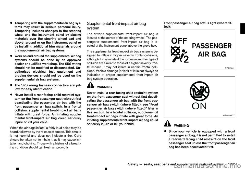
seriously injure or kill your child. Front passenger air bag status light (where fit-
ted):
WARNING
• Since your vehicle is equipped with
af
ront
passenger air bag, it is not permitted to install
ar earward facing child restraint on the front
passenger seat unless the front passenger air
bag has been deactivated first. NP A1531
JVR0264XZ
Safety —seats, seat belts and supplemental restraint system
1-37
Page 73 of 340
•
Remote Control Key system (where fitted)
—“ Push-button ignition switch (models with Re-
mote Control Key system)” in the “5. Starting
and driving” section
• Oil control system (where fitted)
—“
Oil control system (where fitted for diesel
engine model)” later in this section
• Tyre Pressure information (where fitted)
—“
Tyre Pressure Monitoring System (TPMS)
(where fitted)” in the “5. Starting and driving”
section HOW TO USE THE VEHICLE
INFORMATION DISPLAY
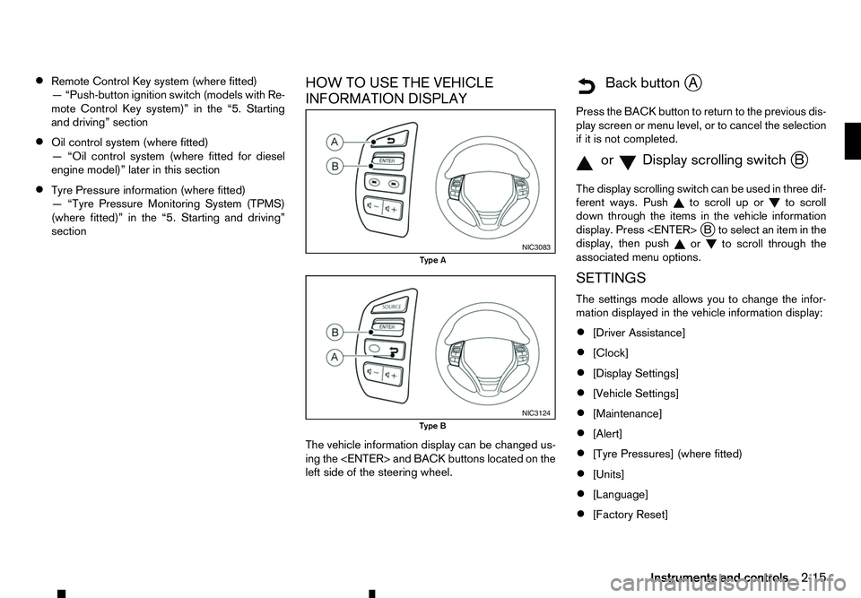
The vehicle information display can be changed us-
ing the
left side of the steering wheel.
m Back
button
jA
Press the BACK button to return to the previous dis-
play screen or menu level, or to cancel the selection if it is not completed.
m orm Display
scrolling switch
jB
The display scrolling switch can be used in three dif-
ferent ways. Push to scroll up or
to scroll
down through the items in the vehicle information
display. Press
display, then push or to scroll through the
associated menu options.
SETTINGS
The settings mode allows you to change the infor-
mation displayed in the vehicle information display:
• [Driver Assistance]
• [Clock]
• [Display Settings]
• [Vehicle Settings]
• [Maintenance]
• [Alert]
• [Tyre Pressures] (where fitted)
• [Units]
• [Language]
• [Factory Reset] NIC3083
Type A
NIC3124
Type B
Instruments and controls2-15
Page 78 of 340
See “Tyre Pressure Monitoring System (TPMS)
(where fitted)” in the “5. Starting and driving” sec-
tion.
Use the or and the
or cancel the calibration process. While the calibra-
tion process is active, the message: [Resetting tyre
pressure system] will be displayed.
[Units]
The following items are available under the [Units]
menu.
• [Distance/Fuel]
• [Tyre Pressures] (where fitted)
• [Temperature]
[Distance/Fuel]:
The unit for the distance and fuel consumption that
displays in the vehicle information display can be
changed to:
• [km, l/100km]
• [km, km/l]
• [miles, MPG]
[Tyre Pressures] (where fitted):
The unit for tyre pressure that displays in the vehicle
information display can be changed to:
• psi
• bar
• kPa •
Kgf/cm
2
Use the or and
the
and change the unit.
[Temperature]:
The temperature that displays in the vehicle informa-
tion display can be changed from:
• °C (Celsius)
• °F (Fahrenheit)
[Language]
The language of the vehicle information display can
be changed to:
• English
• French
• German
• Italian
• Portuguese
• Dutch
• Spanish
• Turkish
• Russian
Use the or and the
and change the language of the vehicle information
display. [Factory Reset]
The settings in the vehicle information display can
be reset back to the factory default. To reset the
vehicle information display:
1. Use the or buttons to select [Settings], and
press the
2. Select [Factory Reset] using the or buttons
and press the
3. Select [Yes] to return all settings back to default by pressing the
To cancel the reset operation select [No] or press
the BACK button located on the left side of the
steering wheel.
2-20 Instruments and controls
Page 90 of 340
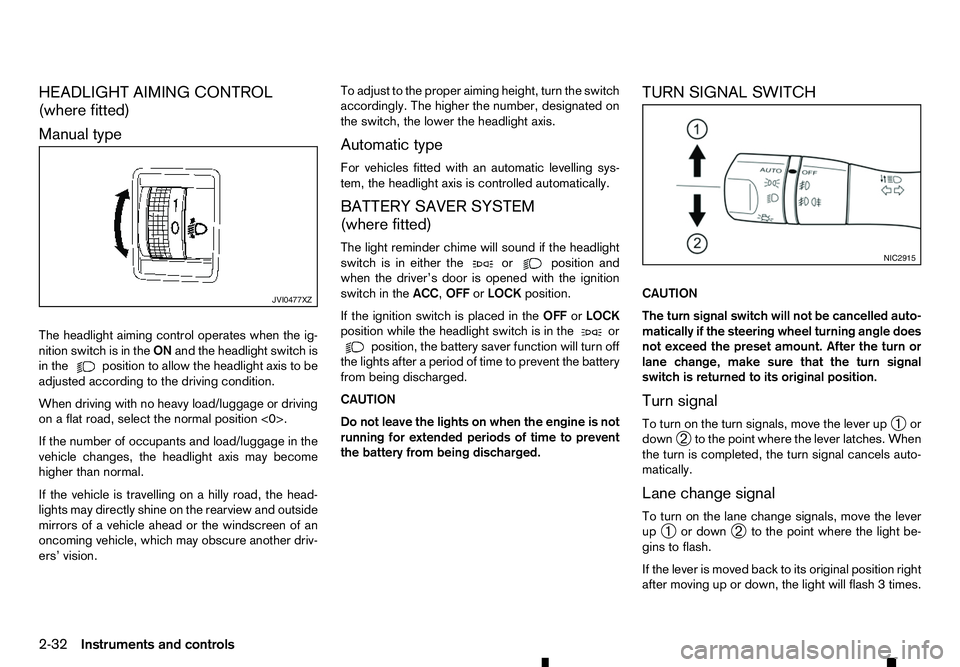
HEADLIGHT AIMING CONTROL
(where fitted)
Manual type
The headlight aiming control operates when the ig- nition switch is in the ONand the headlight switch is
in the position to allow the headlight axis to be
adjusted according to the driving condition.
When driving with no heavy load/luggage or driving
on aflat road, select the normal position <0>.
If the number of occupants and load/luggage in the
vehicle changes, the headlight axis may become
higher than normal.
If the vehicle is travelling on ahilly road, the head-
lights may directly shine on the rearview and outside mirrors of avehicle ahead or the windscreen of an
oncoming vehicle, which may obscure another driv-
ers’ vision. To adjust to the proper aiming height, turn the switch
accordingly. The higher the number, designated on
the switch, the lower the headlight axis.
Automatic type
For vehicles fitted with an automatic levelling sys-
tem, the headlight axis is controlled automatically.
BATTERY SAVER SYSTEM
(where fitted)
The light reminder chime will sound if the headlight
switch is in either the or position and
when the driver’s door is opened with the ignition
switch in the ACC,OFForLOCK position.
If the ignition switch is placed in the OFForLOCK
position while the headlight switch is in the or
position, the battery saver function will turn off
the lights after aperiod of time to prevent the battery
from being discharged.
CAUTION
Do not leave the lights on when the engine is not
running for extended periods of time to prevent
the battery from being discharged. TURN SIGNAL SWITCH
CAUTION
The turn signal switch will not be cancelled auto-
matically if the steering wheel turning angle does
not exceed the preset amount. After the turn or
lane change, make sure that the turn signal
switch is returned to its original position.
Turn signal
To turn on the turn signals, move the lever up
➀or
down ➁to the point where the lever latches. When
the turn is completed, the turn signal cancels auto-
matically.
Lane change signal
To turn on the lane change signals, move the lever
up ➀ or down
➁to the point where the light be-
gins to flash.
If the lever is moved back to its original position right
after moving up or down, the light will flash 3times. JVI0477XZ NIC2915
2-32 Instruments and controls
Page 112 of 340
The Remote Control Key is always communicating
with the vehicle as it receives radio waves. The Re-
mote Control Key system transmits weak radio
waves. Environmental conditions may interfere with
the operation of the Remote Control Key system
under the following operating conditions.
• When operating near
alocation where strong
radio waves are transmitted, such as aTVtower,
power station and broadcasting station.
• When in possession of wireless equipment, such
as am obile telephone, transceiver, and CB ra-
dio.
• When the Remote Control Key is in contact with
or covered by metallic materials.
• When any type of radio wave remote control is
used nearby.
• When the Remote Control Key is placed near an
electric appliance such as
apersonal computer.
In such cases, correct the operating conditions be-
fore using the Remote Control Key function or use
the mechanical key.
Although the life of the battery varies depending on
the operating conditions, the battery’s life is approxi-
mately 2years. If the battery is discharged, replace
it with anew one.
For information regarding replacement of abattery,
see “Remote Control Key battery replacement” in
the “8. Maintenance and do-it-yourself” section.
Since the Remote Control Key is continuously re-
ceiving radio waves, if the key is left near equipment which transmits strong radio waves, such as signals
from
aTVa nd personal computer, the battery life
may become shorter.
Because the steering wheel is locked electrically,
unlocking the steering wheel with the ignition switch
in the LOCK position is impossible when the vehicle
battery is completely discharged. Pay special atten-
tion that the vehicle battery is not completely dis-
charged.
As many as 4Remote Control Keys can be regis-
tered and used with one vehicle. For information
about the purchase and use of additional Remote
Control Keys, contact an approved dealer or quali-
fied workshop.
CAUTION
• Do not allow the Remote Control Key, which
contains electrical components, to come into
contact with water or salt water. This could
affect the system function.
• Do not drop the Remote Control Key.
• Do not strike the Remote Control Key sharply
against another object.
• Do not change or modify the Remote Control
Key.
• Wetting may damage the Remote Control Key.
If the Remote Control Key gets wet, immedi-
ately wipe until it is completely dry.
• If the outside temperature is below −10°C
(14°F), the battery of the Remote Control Key
may not function properly. •
Do not place the Remote Control Key for an
extended period in an area where tempera-
tures exceed 60°C (140°F).
• Do not attach the Remote Control Key to a
key holder that contains
amagnet.
• Do not place the Remote Control Key near
equipment that produces
amagnetic field,
such as aTV, audio equipment and personal
computers.
If an Remote Control Key is lost or stolen, RENAULT
recommends erasing the ID code of that Remote
Control Key from the vehicle. This may prevent the
unauthorised use of the Remote Control Key to op-
erate the vehicle. For information regarding the eras-
ing procedure, contact an approved dealer or quali-
fied workshop.
The Remote Control Key function can be disabled.
For information about disabling the Remote Control
Key function, contact an approved dealer or quali-
fied workshop.
3-8 Pre-driving checks and adjustments
Page 190 of 340
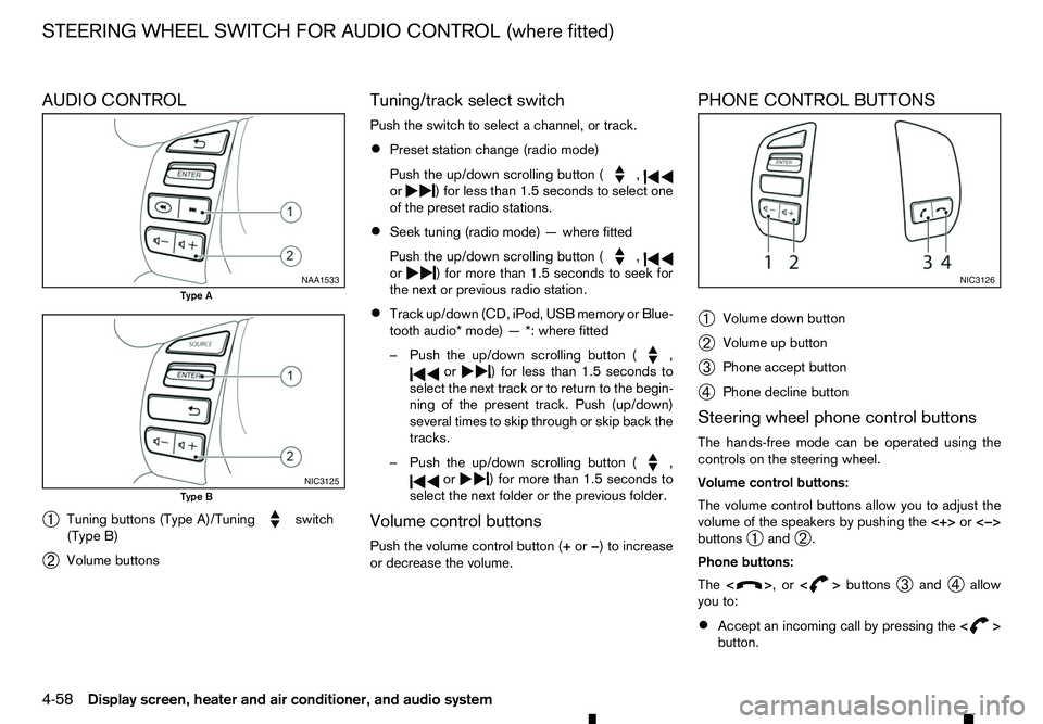
AUDIO CONTROL
➀ Tuning buttons (Type A)/Tuning switch
(Type B)
➁ Volume buttons Tuning/track select switch
Push the switch to select
achannel, or track.
• Preset station change (radio mode)
Push the up/down scrolling button ( ,
or )f
or less than 1.5 seconds to select one
of the preset radio stations.
• Seek tuning (radio mode)
—where fitted
Push the up/down scrolling button ( ,
or )f
or more than 1.5 seconds to seek for
the next or previous radio station.
• Track up/down (CD, iPod, USB memory or Blue-
tooth audio* mode)
—*:where fitted
–P ush the up/down scrolling button ( ,
or )f
or less than 1.5 seconds to
select the next track or to return to the begin-
ning of the present track. Push (up/down)
several times to skip through or skip back the
tracks.
–P ush the up/down scrolling button ( ,
or )f
or more than 1.5 seconds to
select the next folder or the previous folder.
Volume control buttons
Push the volume control button (+ or−)toi ncrease
or decrease the volume. PHONE CONTROL BUTTONS
➀
Volume down button
➁ Volume up button
➂ Phone accept button
➃ Phone decline button
Steering wheel phone control buttons
The hands-free mode can be operated using the
controls on the steering wheel.
Volume control buttons:
The volume control buttons allow you to adjust the
volume of the speakers by pushing the <+>or<−>
buttons ➀and
➁.
Phone buttons:
The < > ,or<
> buttons
➂and
➃allow
you to:
• Accept an incoming call by pressing the
< >
button. NAA1533
Type A
NIC3125
Type B NIC3126
STEERING WHEEL SWITCH FOR AUDIO CONTROL (where fitted)
4-58 Display screen, heater and air conditioner, and audio system
Page 191 of 340
•
Reject an incoming call by pressing the
< >
button during the incoming call.
• End an active call by pushing the
< >
button
once.
• Redial the last outgoing call by pressing the
< >
button for more than
2seconds. BLUETOOTH
®MOBILE PHONE
FEATURE WARNING
Whilst
driving, using the mobile phone is ex-
tremely dangerous because it significantly im-
pairs your concentration and diminishes your re-
action capabilities to sudden changes on the
road, and it may lead to afatal accident. This
applies to all phone call situations such as when
receiving an incoming call, during aphone con-
versation, when calling through the phone book
search, etc.
CAUTION
Certain country jurisdictions prohibit the use of
the mobile phone in the car without hands-free
support.
This chapter provides information about the hands-
free phone system using aBluetooth
®connection.
Bluetooth
®is aw ireless radio communication stan-
dard. This system offers ahands-free facility for your
mobile telephone to enhance driving comfort.
In order to use your mobile phone with the Blue-
tooth
®of the audio system, the mobile phone must
first be setup. For details, see “BLUETOOTH®
settings” later in this section. Once it has been
setup, the hands-free mode is automatically acti-
vated on the registered mobile phone (via Blue-
tooth
®)w hen it comes into range. An
otification message appears on the audio display
when the phone is connected, when an incoming
call is being received, as well as when acall is initi-
ated.
When acall is active, the audio system, microphone
(located in the ceiling in front of the rear view mir-
ror), and steering wheel switches enable hands-free
communication.
If the audio system is in use at the time, the radio,
CD, iPod, USB audio, Bluetooth audio or AUX
source mode will be muted and will stay muted until
the active call has ended.
The Bluetooth
®system may not be able to connect
with your mobile phone for the following reasons:
• The mobile phone is too far away from the ve-
hicle.
• The Bluetooth
®mode on your mobile phone has
not been activated.
• Your mobile phone has not been paired with the
Bluetooth
®system of the audio unit.
• The mobile phone does not support Bluetooth
®
technology (BT Core v2.0).
NOTE
• For models with Audio with Navigation sys-
tem see the separately provided Owner’s
Manual.
• For details, see your mobile phone’s Owner’s
Manual.
BLUETOOTH® HANDS-FREE PHONE SYSTEM (without navigation system
and colour display)
Display screen, heater and air conditioner, and audio system 4-59
Page 198 of 340
EU RED Directive 2014/53/EU
Hereby, Robert Bosch Car Multimedia GmbH de-
clares that the radio equipment type LCN2K70A00/ LCN2K70A10 is in compliance with Directive 2014/
53/EU. The full text of the EU declaration of confor-
mity is available at the following internet address:
http://cert.bosch-carmultimedia.net
Any change of the radio equipment or usage with
other accessories, components or software as
specified will make are-assessment according com-
pliance to the legal approval necessary. Frequency Band
Radiated
Power
(EIRP) Hints/Restriction
2400 MHz –2480
MHz Bluetooth
<10 mW Internal not acces-
sible by user CONTROL BUTTONS AND
MICROPHONE
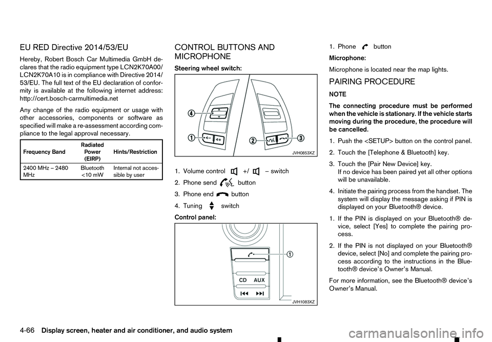
Steering wheel switch:
1. Volume control +/ −s
witch
2. Phone send
button
3. Phone end
button
4. Tuning
switch
Control panel:1. Phone button
Microphone:
Microphone is located near the map lights.
PAIRING PROCEDURE
NOTE
The connecting procedure must be performed
when the vehicle is stationary. If the vehicle starts
moving during the procedure, the procedure will
be cancelled.
1. Push the
2. Touch the [Telephone &Bluetooth] key.
3. Touch the [Pair New Device] key. If no device has been paired yet all other options
will be unavailable.
4. Initiate the pairing process from the handset. The system will display the message asking if PIN is
displayed on your Bluetooth® device.
1. If the PIN is displayed on your Bluetooth® de- vice, select [Yes] to complete the pairing pro-
cess.
2. If the PIN is not displayed on your Bluetooth® device, select [No] and complete the pairing pro-
cess according to the instructions in the Blue- tooth® device’s Owner’s Manual.
For more information, see the Bluetooth® device’s
Owner’s Manual. JVH0853XZ
JVH1083XZ
4-66 Display screen, heater and air conditioner, and audio system
Page 199 of 340
PHONEBOOK
To access the vehicle phonebook:
1. Push the button on the control panel.
2. Select the “Contacts” key.
3. Choose the desired entry from the displayed list.
4. The number of the entry will be displayed on the screen. Touch the number to initiate dialling.
NOTE
To scroll quickly through the list, touch the “A-Z”
key in the upper right corner of the screen. Turn
the ENTER/Scroll dial to choose aletter or num-
ber and then push the ENTER/Scroll dial. The list
will move to the first entry that begins with that
number or letter.
MAKING ACALL
To make acall, follow the procedure below:
1. Push the on the control panel. The “Phone”
screen will appear on the display.
2. Select one of the following options to make a call:
• “Contacts”: Select the name from an entry
stored in the vehicle phonebook.
• “Call Lists”: Select the name from the incom-
ing, outgoing or missed.
• “Redial”: Dial the last outgoing call from the
vehicle. •
“ ”: Input the phone number manually us-
ing akeypad displayed on the screen. For
information on how to use the touch screen,
see “How to use touch screen display” in this
section.
RECEIVING ACALL
When acall is placed to the connected phone, the
display will change to phone mode.
To accept the incoming call, take one of the follow-
ing actions.
• Push the button on the steering wheel.
• Touch the “ ”i
con on the screen.
To reject the incoming call, take one of the following
actions.
• Push the button on the steering wheel.
• Touch the red phone “ ”i
con on the screen.
DURING ACALL
While acall is active, the following options are avail-
able on the screen:
• “Handset”
Select this option to switch control of the phone
call over to the handset.
• “Mute Mic.”
Select this option to mute the microphone. Se-
lect again to reactivate the microphone. •
“ ”i
con
Select to end the phone call.
ENDING ACALL
To end aphone call, select the [ ]i
con on the
screen or push the < >b
utton on the steering
wheel.
BLUETOOTH® SETTINGS
To access the Bluetooth® settings screen:
1. Push the
2. Touch the [Telephone &Bluetooth] key.
Available setting items:
• [Telephone Setup]
See “Telephone setup” later in this section for
details.
• [Pair New Device]
Select to pair
anew Bluetooth® device to the
Bluetooth® Hands-Free Phone System.
• [Select Paired Device]
Select to choose
aBluetooth® device from alist
of those devices paired to the Bluetooth®
Hands-Free Phone System.
• [Delete Paired Device]
Select to delete
aBluetooth® device from alist
of those devices connected/paired to the
Bluetooth® Hands-Free Phone System.
Display screen, heater and air conditioner, and audio system 4-67