check engine RENAULT CAPTUR 2017 1.G Owner's Manual
[x] Cancel search | Manufacturer: RENAULT, Model Year: 2017, Model line: CAPTUR, Model: RENAULT CAPTUR 2017 1.GPages: 248, PDF Size: 6.56 MB
Page 166 of 248
4.6
Engine oil grade
Refer to the Maintenance Service
Booklet for your vehicle.
ENGINE OIL LEVEL: topping up, filling (2/2)OIL CHANGE
Never run the engine in an
enclosed space as exhaust
gases are poisonous.
Engine oil change: if you
are changing the oil when
the engine is hot, be careful
not to scald yourself if the
oil overflows.
Filling: take care when
topping up the oil that
no oil drips onto engine
components - risk of fire.
Remember to refit the cap securely
as there is a risk of fire if oil splashes
onto hot engine components.
When working in the engine
compartment, ensure that
the windscreen wiper stalk
is in the park position.
Risk of injury.
The engine may be hot
when carrying out opera-
tions in close proximity. In
addition, the engine cooling
fan can come on at any moment.
Risk of injury.
Oil change
Service interval: refer to the
Maintenance Service Booklet for your
vehicle.
Oil change capacity
Please refer to the maintenance docu-
ment for your vehicle, or contact an au-
thorised dealer.
Always check the engine oil level using
the dipstick, as explained previously (it
should never fall below the minimum
level, or be over the maximum level on
the dipstick).
Consult your approved dealer at
once if you notice an abnormal or
repeated drop in any of the fluid
levels.Exceeding the maximum
engine oil level
Under no circumstances
must the maximum fill level
be exceeded: risk of damage to the
engine and catalytic converter.
If the oil level exceeds the maximum
level, do not start your vehicle and
contact an approved Dealer.
Page 167 of 248
4.7
Frequency of checking coolant level
Check the coolant level regularly
(very severe damage is likely to be
caused to the engine if it runs out of
coolant).
If the level needs to be topped up, only
use products approved by our Technical
Department which ensure:
– protection against freezing;
– an anti-corrosion protection for the cooling system.
Consult your approved dealer at
once if you notice an abnormal or
repeated drop in any of the fluid
levels.
No operations should be
carried out on the cooling
circuit when the engine is
hot.
Risk of burns.
Replacement interval
Refer to the Maintenance Document for
your vehicle.
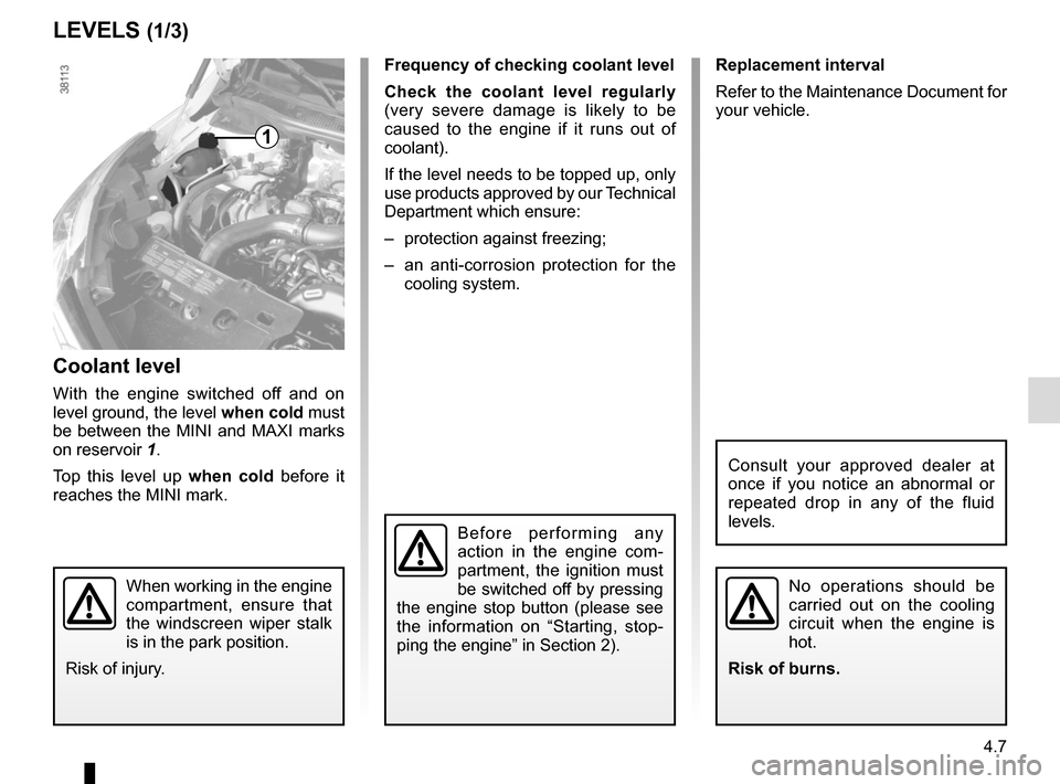
Coolant level
With the engine switched off and on
level ground, the level when cold must
be between the MINI and MAXI marks
on reservoir 1.
Top this level up when cold before it
reaches the MINI mark.
LEVELS (1/3)
1
When working in the engine
compartment, ensure that
the windscreen wiper stalk
is in the park position.
Risk of injury.
Before performing any
action in the engine com-
partment, the ignition must
be switched off by pressing
the engine stop button (please see
the information on “Starting, stop-
ping the engine” in Section 2).
Page 168 of 248
4.8
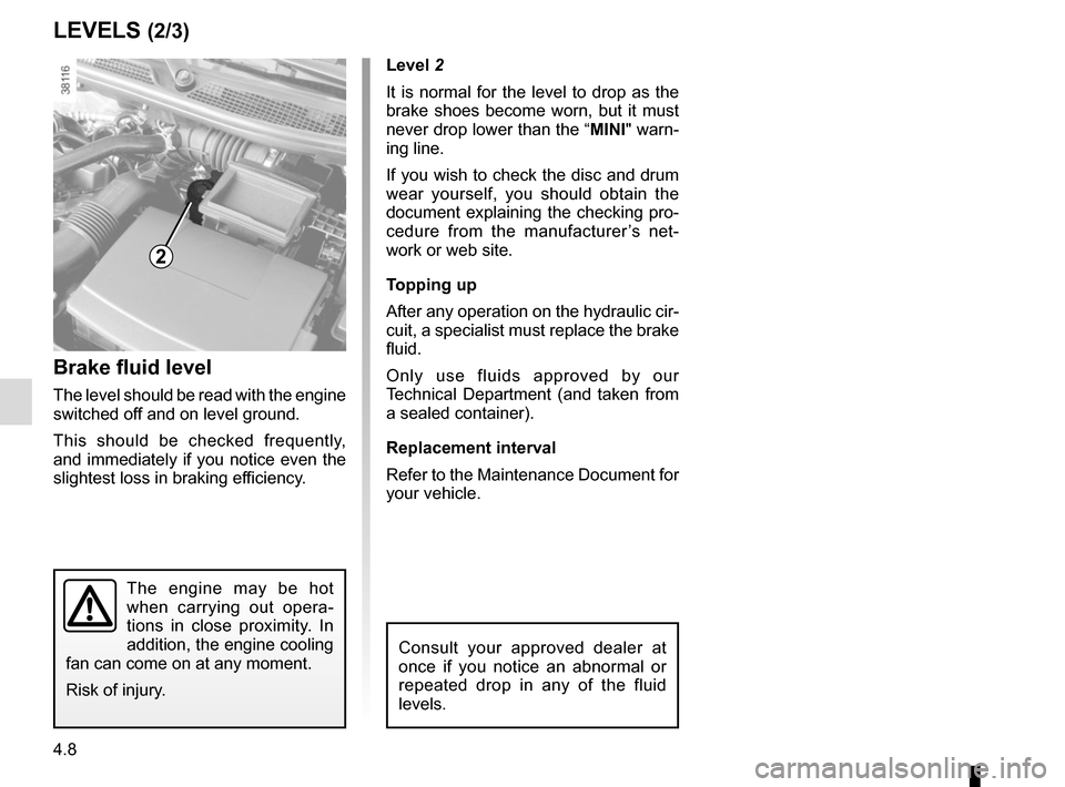
Level 2
It is normal for the level to drop as the
brake shoes become worn, but it must
never drop lower than the “MINI" warn-
ing line.
If you wish to check the disc and drum
wear yourself, you should obtain the
document explaining the checking pro-
cedure from the manufacturer’s net-
work or web site.
Topping up
After any operation on the hydraulic cir-
cuit, a specialist must replace the brake
fluid.
Only use fluids approved by our
Technical Department (and taken from
a sealed container).
Replacement interval
Refer to the Maintenance Document for
your vehicle.
Brake fluid level
The level should be read with the engine
switched off and on level ground.
This should be checked frequently,
and immediately if you notice even the
slightest loss in braking efficiency.
LEVELS (2/3)
2
The engine may be hot
when carrying out opera-
tions in close proximity. In
addition, the engine cooling
fan can come on at any moment.
Risk of injury.
Consult your approved dealer at
once if you notice an abnormal or
repeated drop in any of the fluid
levels.
Page 196 of 248
5.14
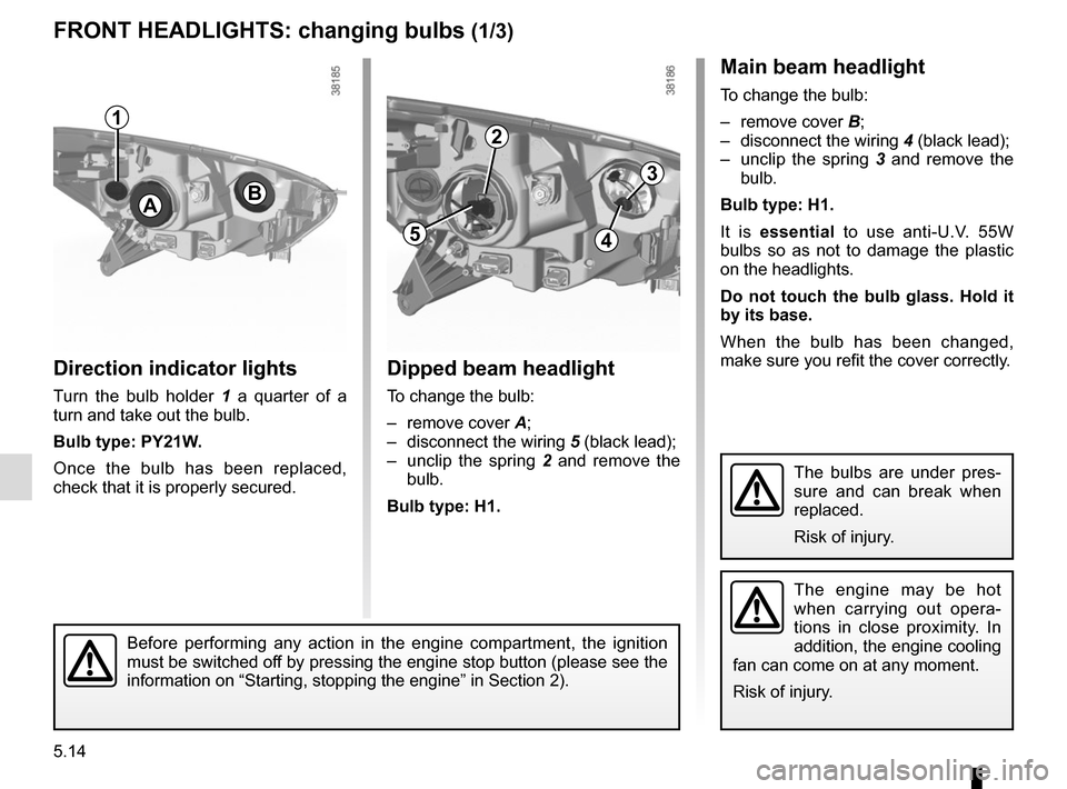
Direction indicator lights
Turn the bulb holder 1 a quarter of a
turn and take out the bulb.
Bulb type: PY21W.
Once the bulb has been replaced,
check that it is properly secured.
Dipped beam headlight
To change the bulb:
– remove cover A;
– disconnect the wiring 5 (black lead);
– unclip the spring 2 and remove the
bulb.
Bulb type: H1.
FRONT HEADLIGHTS: changing bulbs (1/3)
The engine may be hot
when carrying out opera-
tions in close proximity. In
addition, the engine cooling
fan can come on at any moment.
Risk of injury.
B
Main beam headlight
To change the bulb:
– remove cover B;
– disconnect the wiring 4 (black lead);
– unclip the spring 3 and remove the
bulb.
Bulb type: H1.
It is essential to use anti-U.V. 55W
bulbs so as not to damage the plastic
on the headlights.
Do not touch the bulb glass. Hold it
by its base.
When the bulb has been changed,
make sure you refit the cover correctly.
A
1
2
54
3
The bulbs are under pres-
sure and can break when
replaced.
Risk of injury.
Before performing any action in the engine compartment, the ignition
must be switched off by pressing the engine stop button (please see the
information on “Starting, stopping the engine” in Section 2).
Page 205 of 248
5.23
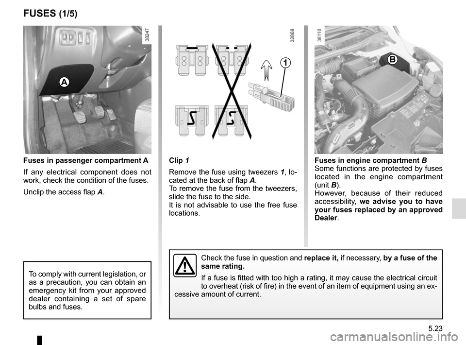
Clip 1
Remove the fuse using tweezers 1, lo-
cated at the back of flap A.
To remove the fuse from the tweezers,
slide the fuse to the side.
It is not advisable to use the free fuse
locations.Fuses in passenger compartment A
If any electrical component does not
work, check the condition of the fuses.
Unclip the access flap A.
FUSES (1/5)
Fuses in engine compartment B
Some functions are protected by fuses
located in the engine compartment
(unit B).
However, because of their reduced
accessibility, we advise you to have
your fuses replaced by an approved
Dealer .
1
A
B
To comply with current legislation, or
as a precaution, you can obtain an
emergency kit from your approved
dealer containing a set of spare
bulbs and fuses.
Check the fuse in question and replace it, if necessary, by a fuse of the
same rating.
If a fuse is fitted with too high a rating, it may cause the electrical \
circuit
to overheat (risk of fire) in the event of an item of equipment using \
an ex-
cessive amount of current.
Page 211 of 248
5.29
BATTERY: breakdown recovery (2/2)
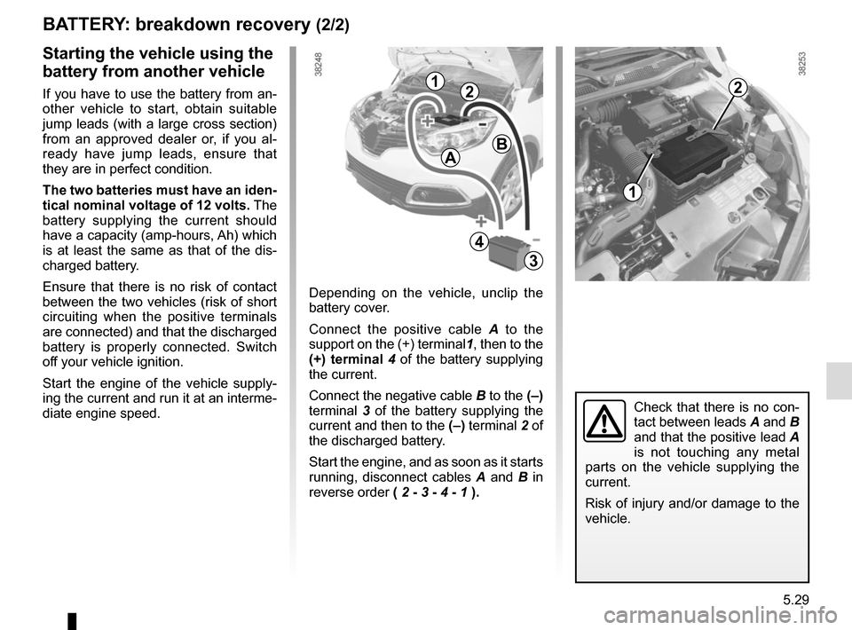
Depending on the vehicle, unclip the
battery cover.
Connect the positive cable A to the
support on the (+) terminal 1, then to the
(+) terminal 4 of the battery supplying
the current.
Connect the negative cable B to the (–)
terminal 3 of the battery supplying the
current and then to the (–) terminal 2 of
the discharged battery.
Start the engine, and as soon as it starts
running, disconnect cables A and B in
reverse order ( 2 - 3 - 4 - 1 ).
Starting the vehicle using the
battery from another vehicle
If you have to use the battery from an-
other vehicle to start, obtain suitable
jump leads (with a large cross section)
from an approved dealer or, if you al-
ready have jump leads, ensure that
they are in perfect condition.
The two batteries must have an iden-
tical nominal voltage of 12 volts. The
battery supplying the current should
have a capacity (amp-hours, Ah) which
is at least the same as that of the dis-
charged battery.
Ensure that there is no risk of contact
between the two vehicles (risk of short
circuiting when the positive terminals
are connected) and that the discharged
battery is properly connected. Switch
off your vehicle ignition.
Start the engine of the vehicle supply-
ing the current and run it at an interme-
diate engine speed.
Check that there is no con-
tact between leads A and B
and that the positive lead A
is not touching any metal
parts on the vehicle supplying the
current.
Risk of injury and/or damage to the
vehicle.
1
212
4
AB
3
Page 213 of 248
5.31
WINDSCREEN WIPER BLADES (1/2)
Check the condition of the wiper
blades. You are responsible for their
service life:
– clean the blades, windscreen and rear screen regularly with soapy
water;
– do not use them when the wind- screen or rear screen are dry;
– free them from the windscreen or rear screen when they have not
been used for a long time.
– In frosty weather, make
sure that the wiper blades
are not stuck by ice (to
avoid the risk of the motor
overheating).
– Check the condition of the wiper
blades.
They should be replaced as soon
as they become less efficient: ap-
proximately once a year.
When changing the blade, when it
has been removed, do not let the
wiper arm fall against the window:
risk of breaking the window.
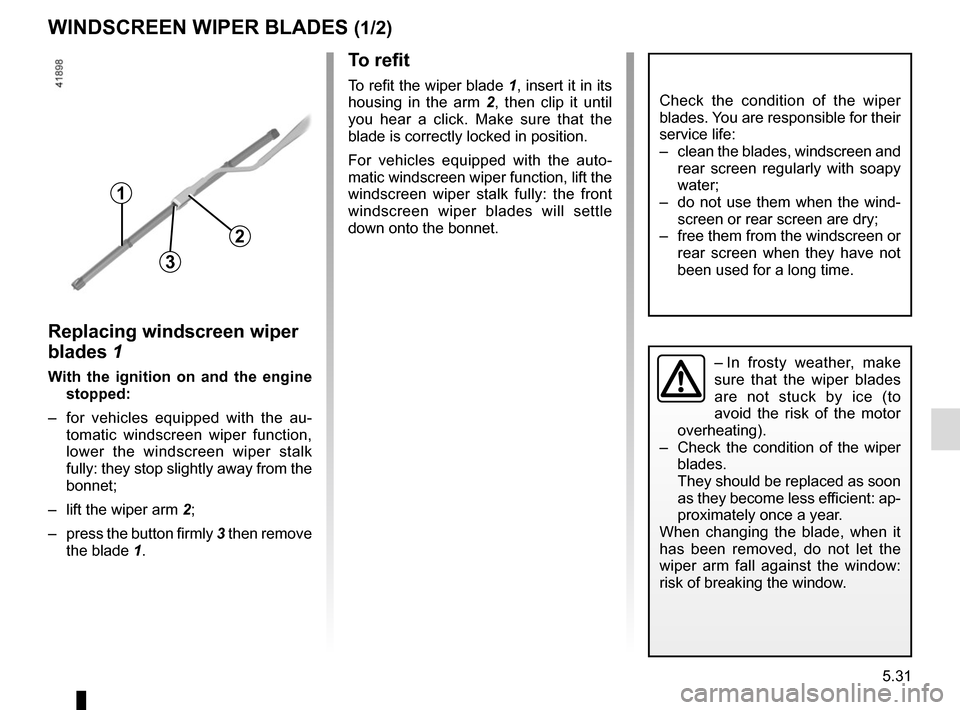
To refit
To refit the wiper blade 1, insert it in its
housing in the arm 2, then clip it until
you hear a click. Make sure that the
blade is correctly locked in position.
For vehicles equipped with the auto-
matic windscreen wiper function, lift the
windscreen wiper stalk fully: the front
windscreen wiper blades will settle
down onto the bonnet.
Replacing windscreen wiper
blades 1
With the ignition on and the engine stopped:
– for vehicles equipped with the au- tomatic windscreen wiper function,
lower the windscreen wiper stalk
fully: they stop slightly away from the
bonnet;
– lift the wiper arm 2;
– press the button firmly 3 then remove the blade 1.
2
1
3
Page 219 of 248
5.37
OPERATING FAULTS (3/6)
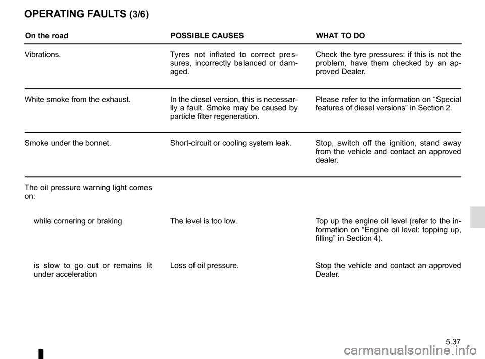
On the roadPOSSIBLE CAUSESWHAT TO DO
Vibrations. Tyres not inflated to correct pres-
sures, incorrectly balanced or dam-
aged. Check the tyre pressures: if this is not the
problem, have them checked by an ap-
proved Dealer.
White smoke from the exhaust. In the diesel version, this is necessar-
ily a fault. Smoke may be caused by
particle filter regeneration. Please refer to the information on “Special
features of diesel versions” in Section 2.
Smoke under the bonnet. Short-circuit or cooling system leak. Stop, switch off the ignition, stand away
from the vehicle and contact an approved
dealer.
The oil pressure warning light comes
on: while cornering or braking The level is too low. Top up the engine oil level (refer to the in-
formation on “Engine oil level: topping up,
filling” in Section 4).
is slow to go out or remains lit
under acceleration Loss of oil pressure.
Stop the vehicle and contact an approved
Dealer.
Page 220 of 248
5.38
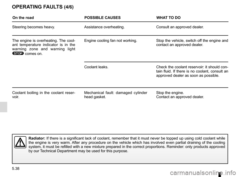
OPERATING FAULTS (4/6)
On the roadPOSSIBLE CAUSESWHAT TO DO
Steering becomes heavy. Assistance overheating. Consult an approved dealer.
The engine is overheating. The cool-
ant temperature indicator is in the
warning zone and warning light
® comes on. Engine cooling fan not working. Stop the vehicle, switch off the engine and
contact an approved dealer.
Coolant leaks. Check the coolant reservoir: it should con- tain fluid. If there is no coolant, consult an
approved dealer as soon as possible.
Coolant boiling in the coolant reser-
voir. Mechanical fault: damaged cylinder
head gasket. Stop the engine.
Contact an approved dealer.
Radiator:
If there is a significant lack of coolant, remember that it must never b\
e topped up using cold coolant while
the engine is very warm. After any procedure on the vehicle which has involved even partial drain\
ing of the cooling
system, it must be refilled with a new mixture prepared in the correct p\
roportions. Reminder: only products approved
by our Technical Department may be used for this purpose.
Page 223 of 248
6.1
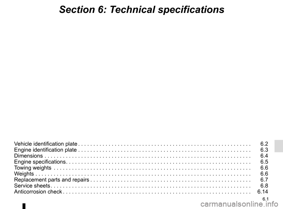
Section 6: Technical specifications
Vehicle identification plate . . . . . . . . . . . . . . . . . . . . . . . . . . . . . . . . . . . . \
. . . . . . . . . . . . . . . . . . . . . 6.2
Engine identification plate . . . . . . . . . . . . . . . . . . . . . . . . . . . . . . . . . . . .\
. . . . . . . . . . . . . . . . . . . . . 6.3
Dimensions . . . . . . . . . . . . . . . . . . . . . . . . . . . . . . . . . . . .\
. . . . . . . . . . . . . . . . . . . . . . . . . . . . . . . . 6.4
Engine specifications . . . . . . . . . . . . . . . . . . . . . . . . . . . . . . . . . . . . \
. . . . . . . . . . . . . . . . . . . . . . . . . 6.5
Towing weights . . . . . . . . . . . . . . . . . . . . . . . . . . . . . . . . . . . .\
. . . . . . . . . . . . . . . . . . . . . . . . . . . . . 6.6
Weights . . . . . . . . . . . . . . . . . . . . . . . . . . . . . . . . . . . .\
. . . . . . . . . . . . . . . . . . . . . . . . . . . . . . . . . . . 6.6
Replacement parts and repairs . . . . . . . . . . . . . . . . . . . . . . . . . . . . . . . . . . . . \
. . . . . . . . . . . . . . . . . 6.7
Service sheets . . . . . . . . . . . . . . . . . . . . . . . . . . . . . . . . . . . . \
. . . . . . . . . . . . . . . . . . . . . . . . . . . . . . 6.8
Anticorrosion check . . . . . . . . . . . . . . . . . . . . . . . . . . . . . . . . . . . . \
. . . . . . . . . . . . . . . . . . . . . . . . . . 6.14