check engine RENAULT CLIO 1997 X57 / 1.G Petrol Engines Workshop Manual
[x] Cancel search | Manufacturer: RENAULT, Model Year: 1997, Model line: CLIO, Model: RENAULT CLIO 1997 X57 / 1.GPages: 55, PDF Size: 4.15 MB
Page 13 of 55
ENGINE AND PERIPHERALS
S
pecifications10
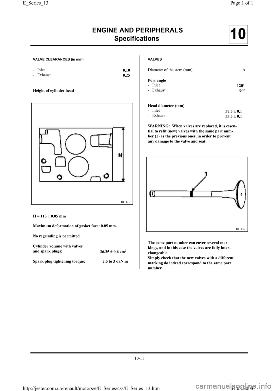
VALVE CLEARANCES (in mm)
- Inlet0.10
- Exhaus
t0.25
Hei
ght of cylinder head
10032R
H = 113 ±
0.05 mm
Maximum deformation of
gasket face: 0.05 mm.
No re
grinding is permitted.
C
ylinder volume with valves
and s
park plugs:
26.25 ±
0,6 cm3
Spark plug tightening torque: 2.5 to 3 daN.m
VALVES
Diameter of the stem (mm) :
7
Port an
gle
- Inle
t120°- Exhaust90°
Head diameter (mm)
- Inlet37.5 ±
0,1
- Exhaust33.5 ±
0,1
WARNING: When valves are re
placed, it is essen-
tial to refit
(new) valves with the same part num-
ber
(1) as the previous ones, in order to prevent
an
y damage to the valve and seat.
10030R
The same part number can cover several mar-
kin
gs, and in this case the valves are fully inter-
chan
geable.
Sim
ply check that the new valves with a different
markin
g do indeed correspond to the same part
number.
10-11
Page 1 of 1 E_Series_13
04.08.2003 http://jester.com.ua/renault/motors/e/E_Series/css/E_Series_13.htm
Page 16 of 55
ENGINE AND PERIPHERALS
S
pecifications10
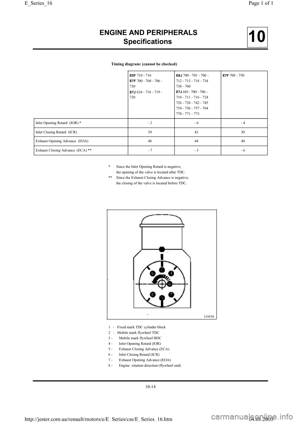
* Since the Inlet Opening Retard is negative,
the opening of the valve is located after TDC.
** Since the Exhaust Closing Advance is negative,
the closing of the valve is located before TDC.
11953S
Timing diagram: (cannot be checked)
1 - Fixed mark TDC cylinder block
2 - Mobile mark flywheel TDC
3 - Mobile mark flywheel BDC
4 - Inlet Opening Retard (IOR)
5 - Exhaust Closing Advance (ECA)
6 - Inlet Closing Retard (ICR)
7 - Exhaust Opening Advance (EOA)
8 - Engine rotation direction (flywheel end) Inlet Opening Retard (IOR) * - 2 - 6 - 4
Inlet Closing Retard (ICR) 39 43 30
Exhaust Opening Advance (EOA) 48 44 40
Exhaust Closing Advance (ECA) ** - 7 - 3 - 6
E5F 710 - 716
E7F 700 - 704 - 706 -
730
E7J 624 -718 - 719 -
720
E6J 700 - 701 - 706 -
712 - 713 - 718 - 734
738 - 760
E7J 601- 700 - 706 -
710 - 711 - 716 - 724
726 - 728 - 742 - 745
754 - 756 - 757 - 764
770 - 771 - 773
E7F 708 - 750
10-14
Page 1 of 1 E_Series_16
04.08.2003 http://jester.com.ua/renault/motors/e/E_Series/css/E_Series_16.htm
Page 19 of 55
ENGINE AND PERIPHERALS
S
pecifications10
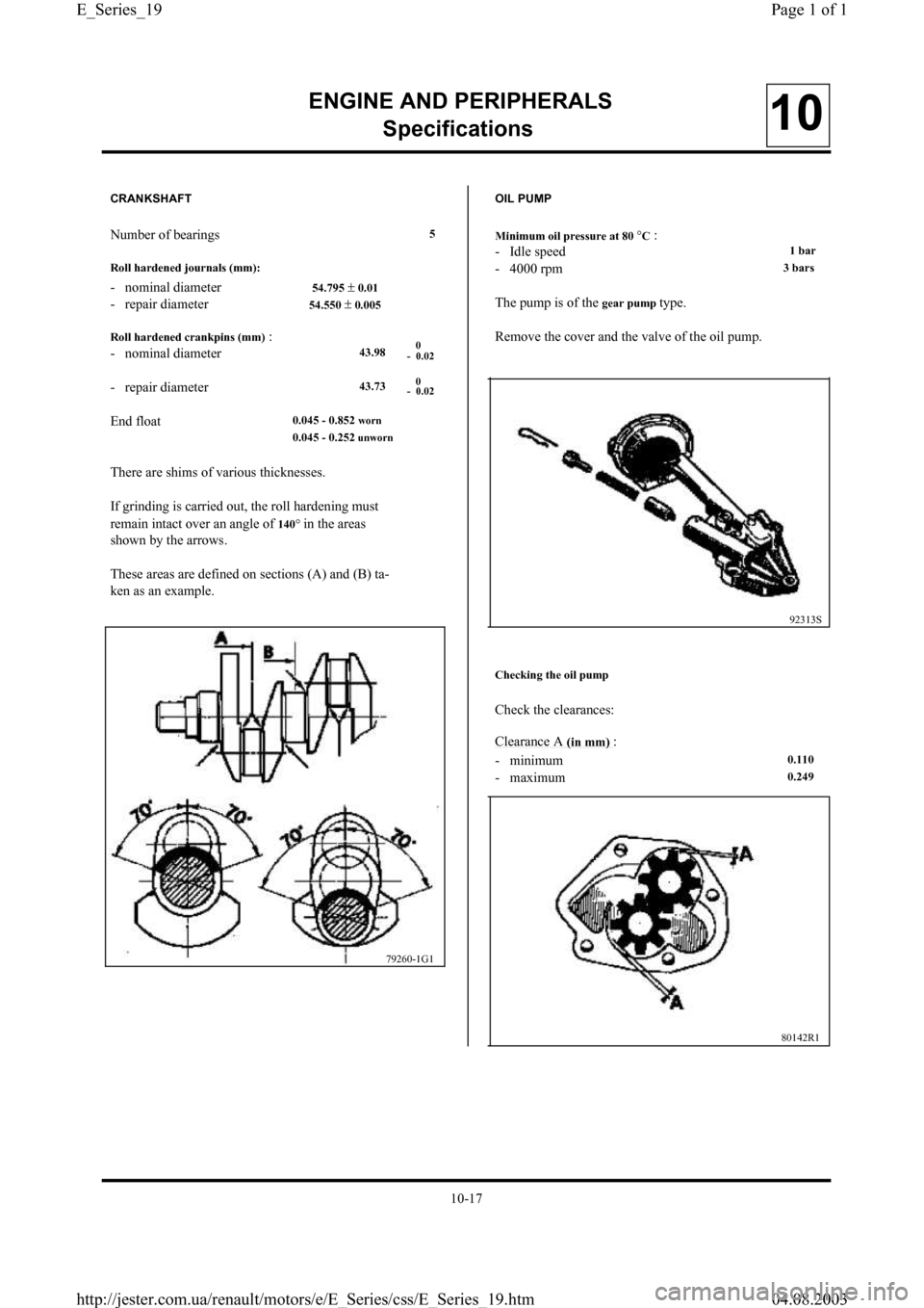
CRANKSHAFT
Number of bearings5
Roll hardened
journals (mm):
- nominal diameter 54.795 ± 0.01
- repair diameter 54.550 ± 0.005
Roll hardened crankpins (mm)
:
- nominal diamete
r43.98
- repair diameter43.73
End float 0.045 - 0.852 worn
0.045 - 0.252 unworn
There are shims of various thicknesses.
If grinding is carried out, the roll hardening mus
t
remain intact over an angle of 140° in the areas
shown by the arrows.
These areas are defined on sections (A) and (B) ta-
ken as an example.
0
- 0.02
0
- 0.02
79260-1G1
OIL PUMP
Minimum oil pressure at 80
°C:
- Idle spee
d1 bar
- 4000 rpm3 bars
The pump is of the gear pump type.
Remove the cover and the valve of the oil pump.
92313S
Checking the oil pump
Check the clearances:
Clearance
A(in mm) :
- minimum
0.110
- maximum0.249
80142R1
10-17
Page 1 of 1 E_Series_19
04.08.2003 http://jester.com.ua/renault/motors/e/E_Series/css/E_Series_19.htm
Page 25 of 55
97160-1S1
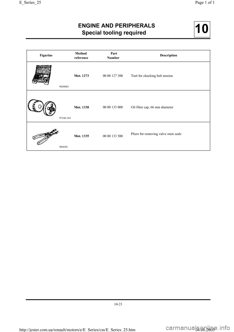
FigurineMethod
referencePart
NumberDescription
ENGINE AND PERIPHERALS
S
pecial tooling required10
96508S1
Mot. 133000 00 133 000 Oil filter cap, 66 mm diameter
Mot. 127300 00 127 300 Tool for checking belt tension
Mot. 133500 00 133 500Pliers for removing valve stem seals
98503S
10-23
Page 1 of 1 E_Series_25
04.08.2003 http://jester.com.ua/renault/motors/e/E_Series/css/E_Series_25.htm
Page 32 of 55
ENGINE AND PERIPHERALS
En
gine repair10
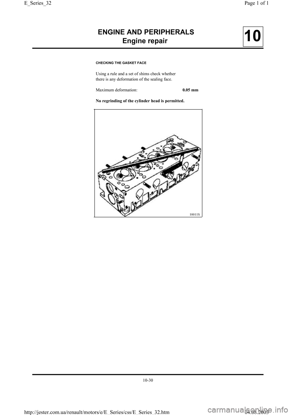
CHECKING THE GASKET FACE
Using a rule and a set of shims check whether
there is any deformation of the sealing face.
Maximum deformation:
0.05 mm
No re
grinding of the cylinder head is permitted.
10011S
10-30
Page 1 of 1 E_Series_32
04.08.2003 http://jester.com.ua/renault/motors/e/E_Series/css/E_Series_32.htm
Page 34 of 55
ENGINE AND PERIPHERALS
En
gine repair10
REFITTING THE CYLINDER HEAD
Lubricate all the parts.
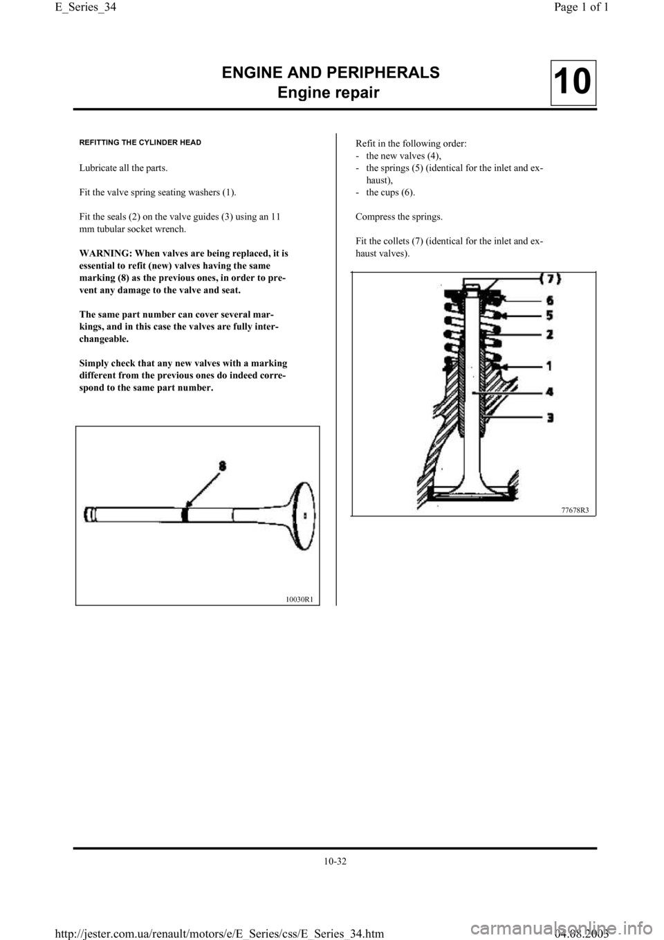
Fit the valve spring seating washers (1).
Fit the seals (2) on the valve guides (3) using an 11
mm tubular socket wrench.
WARNING: When valves are bein
g replaced, it is
essential to refit
(new) valves having the same
markin
g (8) as the previous ones, in order to pre-
vent an
y damage to the valve and seat.
The same
part number can cover several mar-
kin
gs, and in this case the valves are fully inter-
chan
geable.
Sim
ply check that any new valves with a marking
different from the previous ones do indeed corre-
s
pond to the same part number.
10030R1
Refit in the following order:
- the new valves (4),
- the springs (5) (identical for the inlet and ex-
haust),
- the cups (6).
Compress the springs.
Fit the collets (7) (identical for the inlet and ex-
haust valves).
77678R3
10-32
Page 1 of 1 E_Series_34
04.08.2003 http://jester.com.ua/renault/motors/e/E_Series/css/E_Series_34.htm
Page 35 of 55
ENGINE AND PERIPHERALS
En
gine repair10
- the distributor with the wiring loom,
- the fuel pump (if fitted) with new seals,
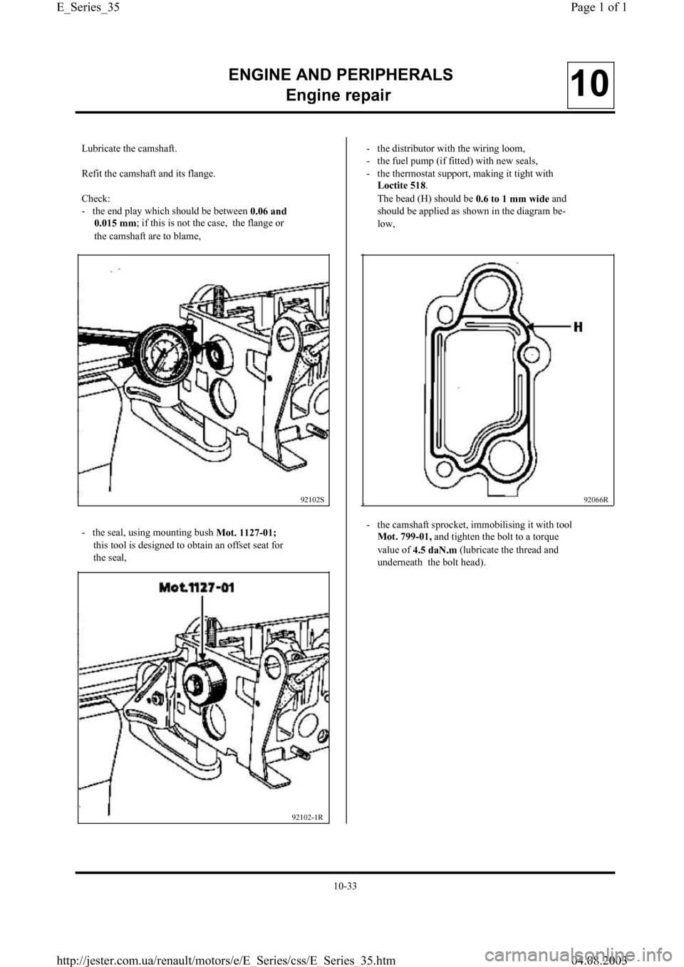
- the thermostat support, making it tight with
Loctite 518.
The bead (H) should be
0.6 to 1 mm wide and
should be applied as shown in the diagram be-
low,
- the seal, using mounting bush
Mot. 1127-01;
this tool is designed to obtain an offset seat fo
r
the seal,
92102S92066R
Lubricate the camshaft.
Refit the camshaft and its flange.
Check:
- the end play which should be between
0.06 and
0.015 mm; if this is not the case, the flange o
r
the camshaft are to blame,
92102-1R
- the camshaft sprocket, immobilising it with tool
Mot. 799-01, and tighten the bolt to a torque
value of
4.5 daN.m (lubricate the thread an
d
underneath the bolt head).
10-33
Page 1 of 1 E_Series_35
04.08.2003 http://jester.com.ua/renault/motors/e/E_Series/css/E_Series_35.htm
Page 40 of 55
ENGINE AND PERIPHERALS
En
gine repair10
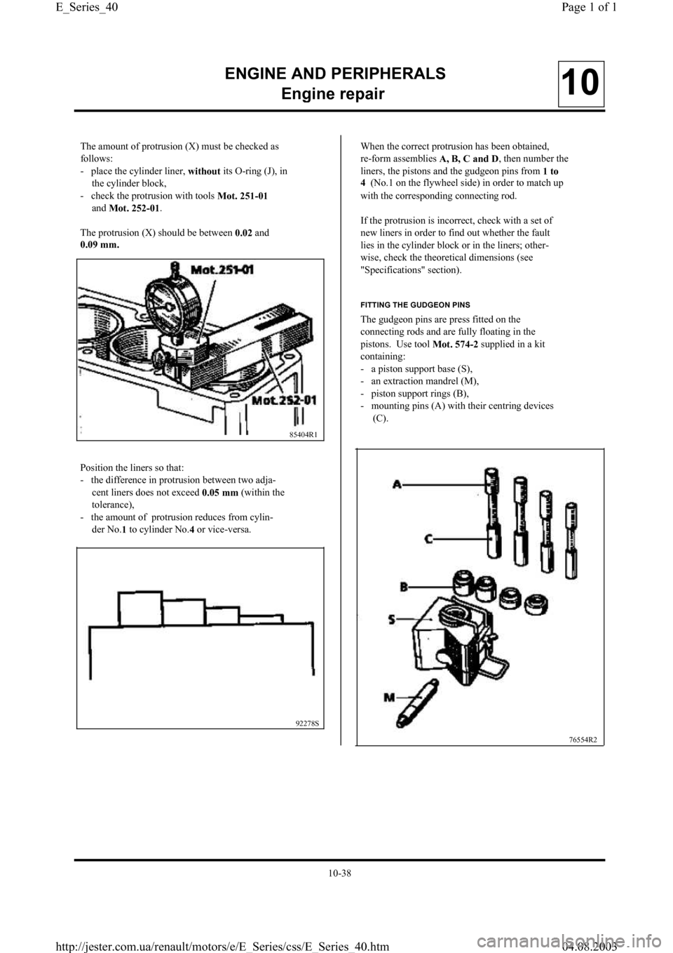
The amount of protrusion (X) must be checked as
follows:
- place the cylinder liner,
without its O-ring (J), in
the cylinder block,
- check the protrusion with tools
Mot. 251-01
and
Mot. 252-01.
The protrusion (X) should be between
0.02 and
0.09 mm.
Position the liners so that:
- the difference in protrusion between two adja-
cent liners does not exceed
0.05 mm (within the
tolerance),
- the amount of protrusion reduces from cylin-
der No.
1 to cylinder No.
4 or vice-versa.
85404R1
92278S
When the correct protrusion has been obtained,
re-form assemblies
A, B, C and D, then number the
liners, the pistons and the gudgeon pins from
1 to
4 (No.1 on the flywheel side) in order to match up
with the corresponding connecting rod.
If the protrusion is incorrect, check with a set of
new liners in order to find out whether the faul
t
lies in the cylinder block or in the liners; other-
wise, check the theoretical dimensions (see
"Specifications" section).
FITTING THE GUDGEON PINS
The gudgeon pins are press fitted on the
connecting rods and are fully floating in the
pistons. Use tool
Mot. 574-2 supplied in a kit
containing:
- a piston support base (S),
- an extraction mandrel (M),
- piston support rings (B),
- mounting pins (A) with their centring devices
(C).
76554R2
10-38
Page 1 of 1 E_Series_40
04.08.2003 http://jester.com.ua/renault/motors/e/E_Series/css/E_Series_40.htm
Page 41 of 55

ENGINE AND PERIPHERALS
En
gine repair10
PREPARATION OF THE GUDGEON PINS
Check that the gudgeon pins are able to slide
freely in the corresponding new pistons.
Use centring device
C13 and mounting tools
A13
or
A13-01 for the shouldered gudgeon pins.
Mount the gudgeon pin (E) on the mounting tool
(A), tighten the centring device (C)
until contact is
made, then slacken b
y a quarter turn.
76716R PREPARATION OF THE CONNECTING RODS
Visually check:
- the condition of the connecting rod (twisting -
straightness),
- the bearing surface between the shells and the
connecting rod bodies (if necessary, remove
any burrs with a grinding wheel to obtain a co
r-
rect bearing surface).
Use a
1500 W heating plate.
Put the little ends on the heating plate.
Ensure that the whole surface of the little end is in
contact with the plate.
Put a piece of self-pickling tin solder with a mel-
ting point of about
250
° onto each little end at (a)
to act as a temperature check.
Heat the little end until the piece of self-pickling
solder melts.
DI1038
12367R
10-39
Page 1 of 1 E_Series_41
04.08.2003 http://jester.com.ua/renault/motors/e/E_Series/css/E_Series_41.htm
Page 42 of 55
ENGINE AND PERIPHERALS
En
gine repair10
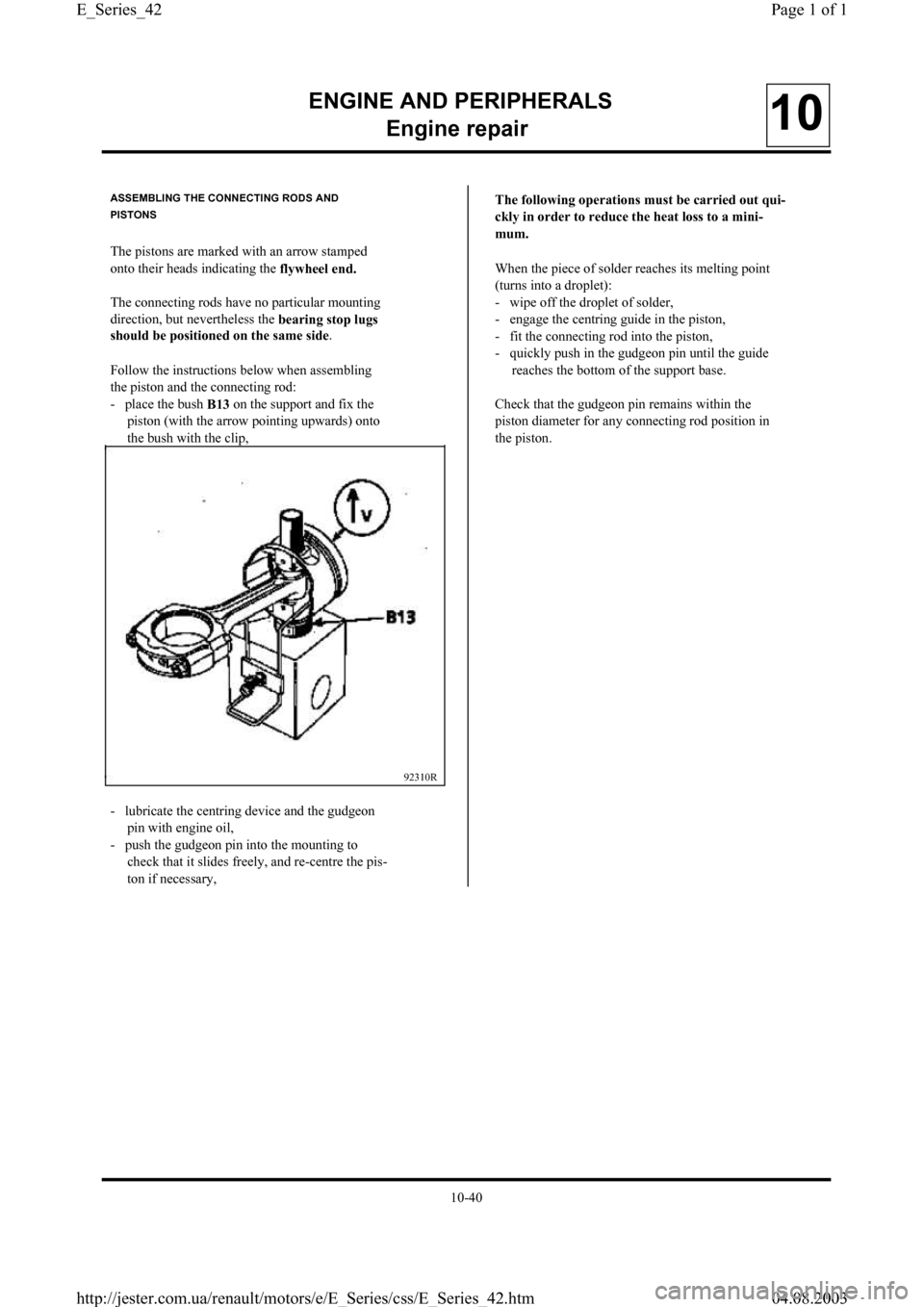
ASSEMBLING THE CONNECTING RODS AND
PISTONS
The pistons are marked with an arrow stamped
onto their heads indicating the
flywheel end.
The connecting rods have no particular mounting
direction, but nevertheless the
bearin
g stop lugs
should be
positioned on the same side.
Follow the instructions below when assembling
the piston and the connecting rod:
- place the bush
B13 on the support and fix the
piston (with the arrow pointing upwards) onto
the bush with the clip,
92310R
- lubricate the centring device and the gudgeon
pin with engine oil,
- push the gudgeon pin into the mounting to
check that it slides freely, and re-centre the pis-
ton if necessary,The followin
g operations must be carried out qui-
ckl
y in order to reduce the heat loss to a mini-
mum.
When the piece of solder reaches its melting poin
t
(turns into a droplet):
- wipe off the droplet of solder,
- engage the centring guide in the piston,
- fit the connecting rod into the piston,
- quickly push in the gudgeon pin until the guide
reaches the bottom of the support base.
Check that the gudgeon pin remains within the
piston diameter for any connecting rod position in
the piston.
10-40
Page 1 of 1 E_Series_42
04.08.2003 http://jester.com.ua/renault/motors/e/E_Series/css/E_Series_42.htm