lock RENAULT CLIO 1997 X57 / 1.G Petrol Engines User Guide
[x] Cancel search | Manufacturer: RENAULT, Model Year: 1997, Model line: CLIO, Model: RENAULT CLIO 1997 X57 / 1.GPages: 55, PDF Size: 4.15 MB
Page 38 of 55
ENGINE AND PERIPHERALS
En
gine repair10
- the water pump,
92312R
- the three bolts mounting the oil pump sprocket
on the hub, and remove the sprocket and chain
assembly,
- the oil pump.
Carry out the marking of the big end shells with
reference to their bodies.
WARNING: Do not use a scriber tool for the mar-
kin
g, in order to avoid starting any cracks in the
connectin
g rods .
Use an indelible
pencil instead.
Remove:
- the big end shells and the bearings,
- the liner clamps
(Mot. 588),
- the "liners - pistons - connecting rods" assem-
blies,
- the bearing shells with their bearings (mar
k
them),
- the crankshaft (recover the side clearance
shims),
- the crankshaft bearings in the cylinder block.
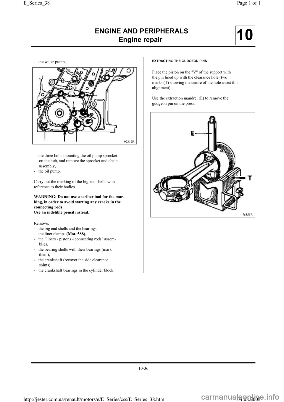
EXTRACTING THE GUDGEON PINS
Place the piston on the "V" of the support with
the pin lined up with the clearance hole (two
marks (T) showing the centre of the hole assist this
alignment).
Use the extraction mandrel (E) to remove the
gudgeon pin on the press.
76555R
10-36
Page 1 of 1 E_Series_38
04.08.2003 http://jester.com.ua/renault/motors/e/E_Series/css/E_Series_38.htm
Page 39 of 55
ENGINE AND PERIPHERALS
En
gine repair10
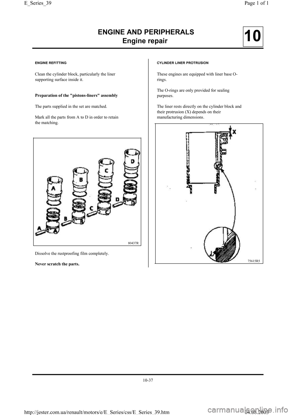
80437R ENGINE REFITTING
Clean the cylinder block, particularly the liner
supporting surface inside it.
Pre
paration of the "pistons-liners" assembly
The parts supplied in the set are matched.
Mark all the parts from A to D in order to retain
the matching.
Dissolve the rustproofing film completely.
Never scratch the
parts.
CYLINDER LINER PROTRUSION
These engines are equipped with liner base O-
rings.
The O-rings are only provided for sealing
purposes.
The liner rests directly on the cylinder block and
their protrusion (X) depends on thei
r
manufacturing dimensions.
75615R5
10-37
Page 1 of 1 E_Series_39
04.08.2003 http://jester.com.ua/renault/motors/e/E_Series/css/E_Series_39.htm
Page 40 of 55
ENGINE AND PERIPHERALS
En
gine repair10
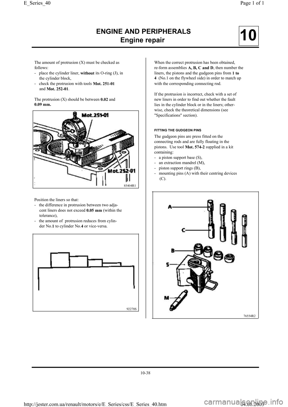
The amount of protrusion (X) must be checked as
follows:
- place the cylinder liner,
without its O-ring (J), in
the cylinder block,
- check the protrusion with tools
Mot. 251-01
and
Mot. 252-01.
The protrusion (X) should be between
0.02 and
0.09 mm.
Position the liners so that:
- the difference in protrusion between two adja-
cent liners does not exceed
0.05 mm (within the
tolerance),
- the amount of protrusion reduces from cylin-
der No.
1 to cylinder No.
4 or vice-versa.
85404R1
92278S
When the correct protrusion has been obtained,
re-form assemblies
A, B, C and D, then number the
liners, the pistons and the gudgeon pins from
1 to
4 (No.1 on the flywheel side) in order to match up
with the corresponding connecting rod.
If the protrusion is incorrect, check with a set of
new liners in order to find out whether the faul
t
lies in the cylinder block or in the liners; other-
wise, check the theoretical dimensions (see
"Specifications" section).
FITTING THE GUDGEON PINS
The gudgeon pins are press fitted on the
connecting rods and are fully floating in the
pistons. Use tool
Mot. 574-2 supplied in a kit
containing:
- a piston support base (S),
- an extraction mandrel (M),
- piston support rings (B),
- mounting pins (A) with their centring devices
(C).
76554R2
10-38
Page 1 of 1 E_Series_40
04.08.2003 http://jester.com.ua/renault/motors/e/E_Series/css/E_Series_40.htm
Page 43 of 55
ENGINE AND PERIPHERALS
En
gine repair10
92317S
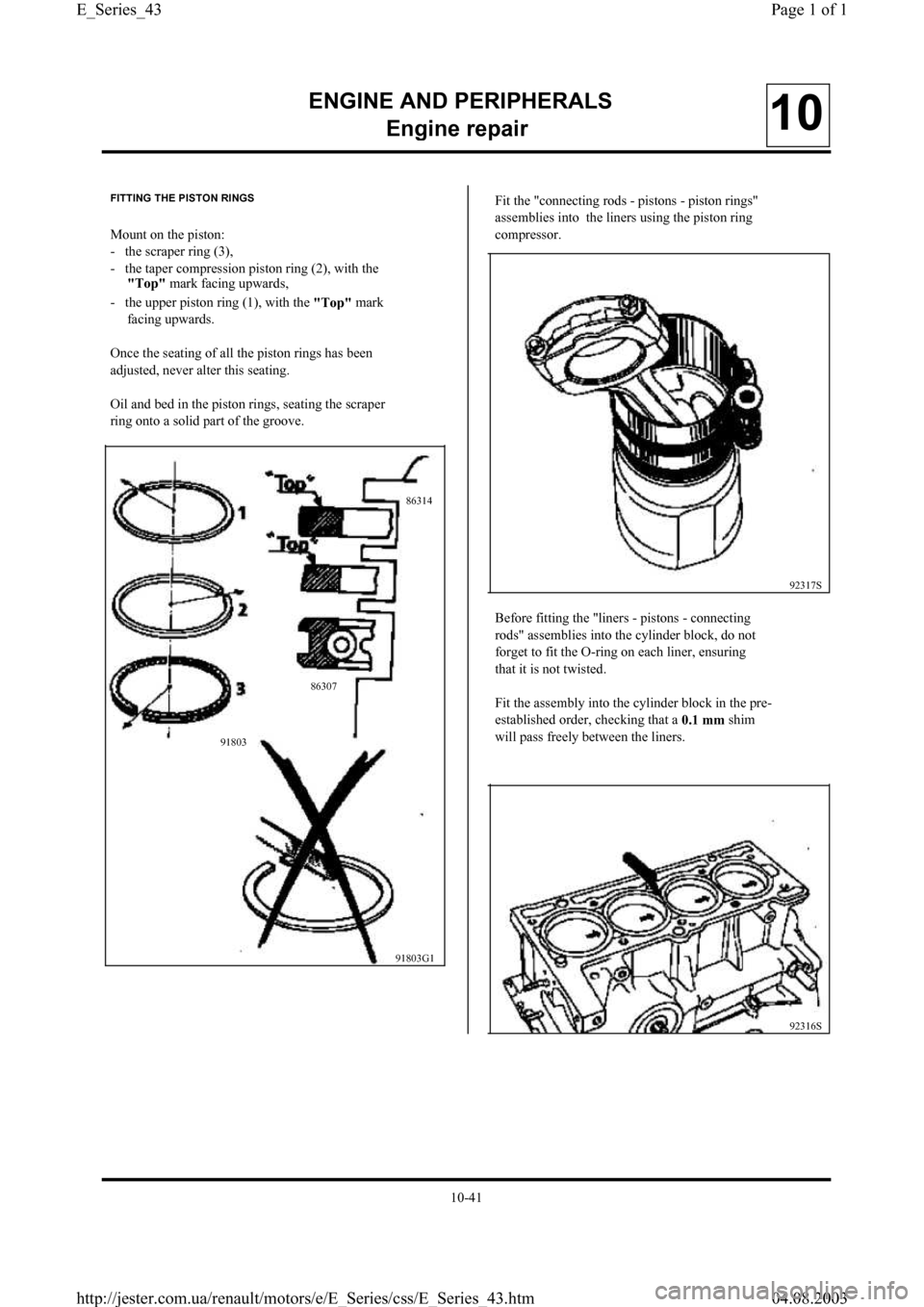
91803G1 FITTING THE PISTON RINGS
Mount on the piston:
- the scraper ring (3),
- the taper compression piston ring (2), with the
"To
p" mark facing upwards,
- the upper piston ring (1), with the
"To
p" mark
facing upwards.
Once the seating of all the piston rings has been
adjusted, never alter this seating.
Oil and bed in the piston rings, seating the scrape
r
ring onto a solid part of the groove.Fit the "connecting rods - pistons - piston rings"
assemblies into the liners using the piston ring
compressor.
Before fitting the "liners - pistons - connecting
rods" assemblies into the cylinder block, do no
t
forget to fit the O-ring on each liner, ensuring
that it is not twisted.
Fit the assembly into the cylinder block in the pre-
established order, checking that a
0.1 mm shim
will pass freely between the liners.
92316S 918038630786314
10-41
Page 1 of 1 E_Series_43
04.08.2003 http://jester.com.ua/renault/motors/e/E_Series/css/E_Series_43.htm
Page 44 of 55

ENGINE AND PERIPHERALS
En
gine repair10
Immobilise the liners using tool
Mot. 588.
92062R
Shims of the following thicknesses (mm) are avai-
lable from the Parts Department:
2.80; 2.85; 2.90;
2.95.
Refit the connecting rod shells and tighten the
nuts to a torque value of
4.2 daN.m.
Check:
- the end float of the connecting rods,
- that the assembly is able to rotate properly. Fit the crankshaft and the end float shims.
Lubricate the crankpins and the main bearing
journals with engine oil.
Refit the crankshaft bearing shells.
Apply a thin layer of
RHODORSEAL 5661 on bea-
ring
N°
1 zone (K) and tighten the bolts to
2.5 daN.m , then angle tighten to
43°
± 6°.
Check the end floatof the crankshaft, which
should be between:
-
0.045 and 0.852 mmwith wear,
-
0.045 and 0.252 mmwithout wear.
92314S MOUNTING THE BEARING SHELLS
The connecting rod bearing shells are identical.
The crankshaft bearing shells are grooved on the
cylinder block side.
92315R
The upper shell of bearing
No. 5 is a special one
and is also grooved.
10-42
Page 1 of 1 E_Series_44
04.08.2003 http://jester.com.ua/renault/motors/e/E_Series/css/E_Series_44.htm
Page 49 of 55
ENGINE AND PERIPHERALS
En
gine repair10
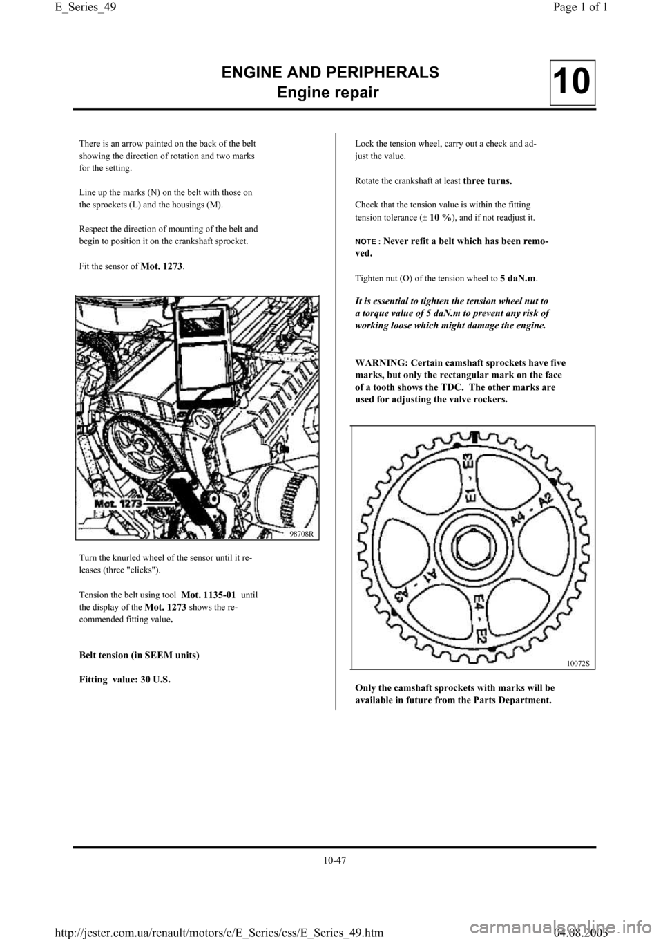
There is an arrow painted on the back of the belt
showing the direction of rotation and two marks
for the setting.
Line up the marks (N) on the belt with those on
the sprockets (L) and the housings (M).
Respect the direction of mounting of the belt and
begin to position it on the crankshaft sprocket.
Fit the sensor of
Mot. 1273.
98708R
Turn the knurled wheel of the sensor until it re-
leases (three "clicks").
Tension the belt using tool
Mot. 1135-01 until
the display of the
Mot. 1273 shows the re-
commended fitting value
.
Belt tension (in SEEM units)
Fitting value: 30 U.S.
Lock the tension wheel, carry out a check and ad-
just the value.
Rotate the crankshaft at least
three turns.
Check that the tension value is within the fitting
tension tolerance (
±10 %), and if not readjust it.
NOTE : Never refit a belt which has been remo-
ved.
Tighten nut (O) of the tension wheel to 5 daN.m.
It is essential to tighten the tension wheel nut to
a tor
que value of 5 daN.m to prevent any risk of
working loose which might damage the engine.
WARNING: Certain camshaft s
prockets have five
marks, but onl
y the rectangular mark on the face
of a tooth shows the TDC. The other marks are
used for ad
justing the valve rockers.
10072S
Only the camshaft sprockets with marks will be
available in future from the Parts De
partment.
10-47
Page 1 of 1 E_Series_49
04.08.2003 http://jester.com.ua/renault/motors/e/E_Series/css/E_Series_49.htm
Page 51 of 55
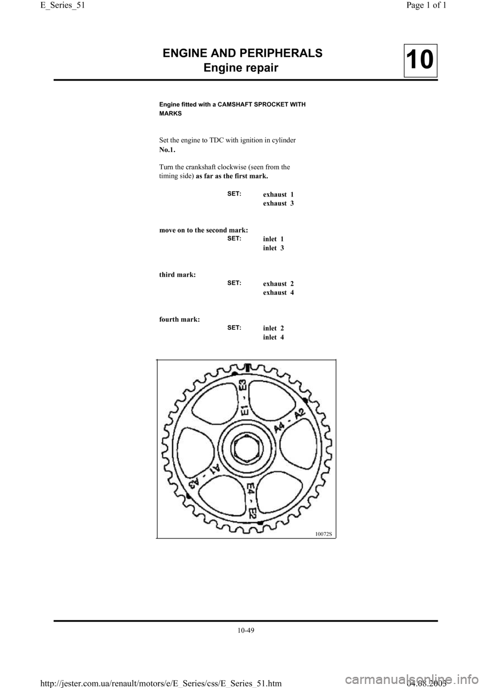
Engine fitted with a CAMSHAFT SPROCKET WITH
MARKS
Set the engine to TDC with ignition in cylinder
No.1.
Turn the crankshaft clockwise
(seen from the
timing side)
as far as the first mark.
SET:exhaust 1
exhaust 3
move on to the second mark:
SET:inlet 1
inlet 3
third mark:
SET:exhaust 2
exhaust 4
fourth mark:
SET:inlet 2
inlet 4
ENGINE AND PERIPHERALS
En
gine repair10
10072S
10-49
Page 1 of 1 E_Series_51
04.08.2003 http://jester.com.ua/renault/motors/e/E_Series/css/E_Series_51.htm
Page 52 of 55
ENGINE AND PERIPHERALS
En
gine repair10
Refit:
- the cylinder head cover fitted with a new gas-
ket,
- the coolant pipe and the dipstick guide tube
with new seals,
- the timing cover,
- the crankshaft pulley tightening the bolt to
2 daN.m, then angle tighten to
68°
±6°,
- the inlet and exhaust manifolds, tightening the
nuts to
2.5 daN.m,
- the accessories belt or belts.
Tensionin
g process
Engine cold (ambient temperature).
Fit the new belt.
Position the sensor of the
Mot. 1273.
Turn the knurled wheel of the sensor until it re-
leases (three "clicks").
Tension the belt until the fitting value recommen-
ded on the next page is shown on the display of
the
Mot. 1273.
Lock the tension wheel, carry out a check and ad-
just the value.
Rotate the crankshaft
three turns.
Check that the tension value is within the fitting
tension tolerance, and if not readjust it.
NOTE : Never refit a belt which has been remo-
ved.
10-50
Page 1 of 1 E_Series_52
04.08.2003 http://jester.com.ua/renault/motors/e/E_Series/css/E_Series_52.htm