check engine RENAULT CLIO 2012 X85 / 3.G Workshop Manual
[x] Cancel search | Manufacturer: RENAULT, Model Year: 2012, Model line: CLIO, Model: RENAULT CLIO 2012 X85 / 3.GPages: 268, PDF Size: 8.73 MB
Page 184 of 268
Downloaded from www.Manualslib.com manuals search engine levels .................................................... (up to the end of the DU)
engine coolant ....................................................... (current page)
tanks and reservoirs coolant ............................................................. (current page)
levels: coolant ............................................................. (current page)
4.8
ENG_UD19908_3
Niveau / Filtres (X85 - B85 - C85 - S85 - K85 - Renault)
ENG_NU_853-7_BCSK85_Renault_4
Jaune NoirNoir texte
Frequency of checking coolant level
Check the coolant level regularly
(very severe damage is likely to be
caused to the engine if it runs out of
coolant).
If the level needs to be topped up, only
use products approved by our Technical
Department which ensure:
– protection against freezing;
– an anti-corrosion protection for the
cooling system.
Levels
engine coolant
Consult your approved dealer at
once if you notice an abnormal or
repeated drop in any of the fluid
levels.
No operations should be
carried out on the cooling
circuit when the engine is
hot.
Risk of burns.
Replacement interval
Refer to the Maintenance Service
Booklet for your vehicle.
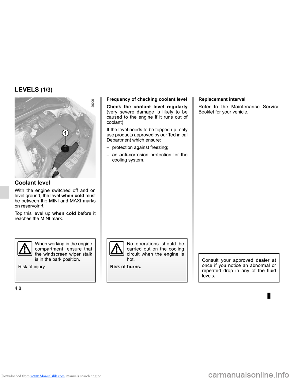
Coolant level
With the engine switched off and on
level ground, the level when cold must
be between the MINI and MAXI marks
on reservoir 1.
Top this level up when cold before it
reaches the MINI mark.
LEVELS (1/3)
1
When working in the engine
compartment, ensure that
the windscreen wiper stalk
is in the park position.
Risk of injury.
Page 185 of 268
Downloaded from www.Manualslib.com manuals search engine brake fluid .............................................................. (current page)
levels: brake fluid ........................................................ (current page)
tanks and reservoirs brake fluid ........................................................ (current page)
JauneNoirNoir texte
4.9
ENG_UD19908_3
Niveau / Filtres (X85 - B85 - C85 - S85 - K85 - Renault)
ENG_NU_853-7_BCSK85_Renault_4
brake fluid
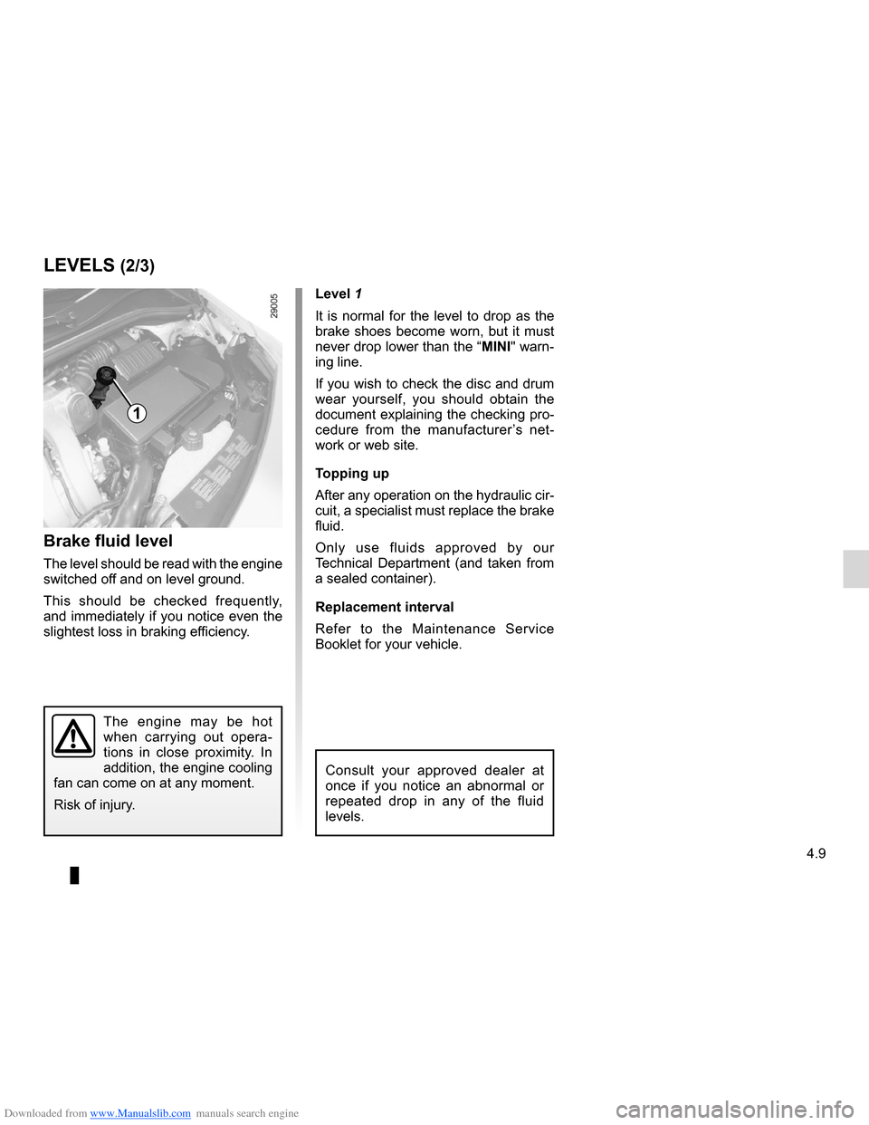
Level 1
It is normal for the level to drop as the
brake shoes become worn, but it must
never drop lower than the “MINI" warn-
ing line.
If you wish to check the disc and drum
wear yourself, you should obtain the
document explaining the checking pro-
cedure from the manufacturer ’s net -
work or web site.
Topping up
After any operation on the hydraulic cir-
cuit, a specialist must replace the brake
fluid.
Only use fluids approved by our
Technical Department (and taken from
a sealed container).
Replacement interval
Refer to the Maintenance Service
Booklet for your vehicle.
Brake fluid level
The level should be read with the engine
switched off and on level ground.
This should be checked frequently,
and immediately if you notice even the
slightest loss in braking efficiency.
LEVELS (2/3)
1
The engine may be hot
when carrying out opera -
tions in close proximity. In
addition, the engine cooling
fan can come on at any moment.
Risk of injury.
Consult your approved dealer at
once if you notice an abnormal or
repeated drop in any of the fluid
levels.
Page 190 of 268
Downloaded from www.Manualslib.com manuals search engine 4.14
ENG_UD25392_1
Entretien de la carrosserie (X95 - J95 - R95 - Renault)
ENG_NU_853-7_BCSK85_Renault_4
– bird droppings , which cause a
chemical reaction with the paint that
rapidly discolours paintwork and
may even cause the paint to peel
off;
Wash the vehicle immediately to
remove these marks since it is im -
possible to remove them by polish -
ing;
– salt, particularly in the wheel arches
and underneath the body after driv -
ing in areas where the roads have
been gritted.
Using a roller type car wash
Return the windscreen wiper stalk to
the Park position (refer to the informa-
tion on the “Windscreen washer, wiper”
in Section 1). Check the mounting of
external accessories, additional lights
and mirrors, and ensure that the wiper
blades are secured with adhesive tape.
Remove the radio aerial mast if your
vehicle is fitted with this equipment.
Remember to remove the tape and refit
the antenna after washing.y ou should
Observe the vehicle stopping distances
when driving on gravelled surfaces to
prevent paint damage.
Repair, or have repaired quickly, areas
where the paint has been damaged, to
prevent corrosion spreading.
Remember to visit the body shop pe -
riodically in order to maintain your
anti-corrosion warranty. Refer to the
Maintenance Service Booklet.
Respect local regulations about wash -
ing vehicles (e.g. do not wash your ve-
hicle on a public highway).
Wash your car frequently, with the
engine off, with cleaning products rec-
ommended by the manufacturer (never
use abrasive products). Rinse thor -
oughly beforehand with a jet:
– spots of tree resin and industrial
grime;
– mud in the wheel arches and under -
neath the body which forms damp
patches;
BODyWORK MAINTENANCE (2/2)
If it is necessary to clean mechani -
cal components, hinges, etc., spray
them with products approved by our
Technical Department to protect them
after they have been cleaned.
Cleaning the headlights
As the headlights are made of plastic
“glass”, use a soft cloth or cotton wool
to clean them. If this does not clean
them properly, moisten the cloth with
soapy water, then wipe clean with a soft
damp cloth or cotton wool.
Finally, carefully dry off with a soft dry
cloth.
Cleaning products containing alco -
hol must not be used.
We have selected special products
to care for your vehicle and you can
obtain these from the manufactur -
er’s accessory outlets.
Page 194 of 268

Downloaded from www.Manualslib.com manuals search engine puncture................................................ (up to the end of the DU)
emergency spare wheel ....................... (up to the end of the DU)
5.2
ENG_UD24923_2
Roue de secours (X85 - B85 - C85 - S85 - K85 - Renault)
ENG_NU_853-7_BCSK85_Renault_5
Jaune NoirNoir texte
In case of puncture
Depending on the vehicle, a tyre infla-
tion kit or emergency spare wheel is
provided (refer to the following pages).
If the emergency spare wheel has been stored for several years, have it
checked by your Dealer to ensure that it is safe to use.
Vehicle fitted with an emergency spare wheel that differs from the
other wheels:
– Never fit more than one emergency spare wheel to the same vehicle.
– When this is fitted to the vehicle, which must only be a temporary measure, the
driving speed must not exceed the speed indicated on the label on the wh\
eel.
– Replace the emergency spare wheel as soon as possible with a wheel identi -
cal to the original one.
– Fitting an emergency spare wheel may alter the way the vehicle usually runs.
Avoid sudden acceleration or deceleration and reduce your speed when cor-
nering.
– Fitting the damaged wheel into the emergency spare wheel housing will reduce
the vehicle’s ground clearance: avoid driving over any obstacles.
– If you need to use snow chains, fit the emergency spare wheel to the rear axle
and check the tyre pressure.
PUNCTURE, EMERGENCY SPARE WHEEL (1/4)
Page 197 of 268
Downloaded from www.Manualslib.com manuals search engine JauneNoirNoir texte
5.5
ENG_UD24923_2
Roue de secours (X85 - B85 - C85 - S85 - K85 - Renault)
ENG_NU_853-7_BCSK85_Renault_5
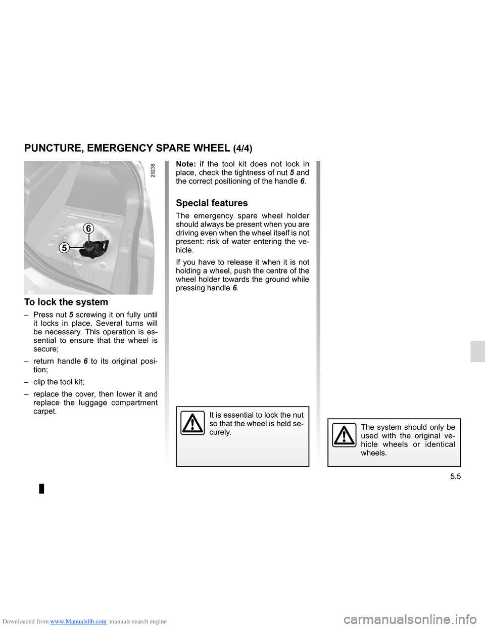
Note: if the tool kit does not lock in
place, check the tightness of nut 5 and
the correct positioning of the handle 6.
Special features
The emergency spare wheel holder
should always be present when you are
driving even when the wheel itself is not
present: risk of water entering the ve -
hicle.
If you have to release it when it is not
holding a wheel, push the centre of the
wheel holder towards the ground while
pressing handle 6.
To lock the system
– Press nut 5 screwing it on fully until
it locks in place. Several turns will
be necessary. This operation is es -
sential to ensure that the wheel is
secure;
– return handle 6 to its original posi -
tion;
– clip the tool kit;
– replace the cover, then lower it and
replace the luggage compartment
carpet.
PUNCTURE, EMERGENCY SPARE WHEEL (4/4)
The system should only be
used with the original ve -
hicle wheels or identical
wheels.
It is essential to lock the nut
so that the wheel is held se-
curely.
6
5
Page 198 of 268

Downloaded from www.Manualslib.com manuals search engine tyre inflation kit...................................... (up to the end of the DU)
5.6
ENG_UD22318_3
Kit de gonflage des pneumatiques (X85 - B85 - C85 - S85 - K85 - Renault\
)
ENG_NU_853-7_BCSK85_Renault_5
Jaune NoirNoir texte
Tyre pressure kit
TYRE PRESSURE KIT (1/3)
The kit is only approved for
inflating the tyres of the ve-
hicle originally equipped
with the kit.
It must never be used to inflate
the tyres of another vehicle, or any
other inflatable object (rubber ring,
rubber boat, etc.).
Avoid spillage on skin when han -
dling the repair liquid bottle. If drop-
lets do leak out, rinse them off with
plenty of water.
Keep the repair kit away from chil -
dren.
Do not dispose of the empty bottle
in the countryside. Return it to your
approved dealer or to a recycling or-
ganisation.
The bottle has a limited service
life which is indicated on its label.
Check the expiry date.
Contact an approved dealer to re -
place the inflation tube and repair
product bottle.
A
B
The kit repairs tyres when
tread A has been dam -
aged by objects smaller
than 4 mm. It cannot repair
all types of puncture, such as cuts
larger than 4 mm, or cuts in tyre
sidewall B.
Ensure also that the wheel rim is in
good condition.
Do not pull out the foreign body
causing the puncture if it is still in
the tyre.
Do not attempt to use the
inflation kit if the tyre has
been damaged as a result
of driving with a puncture.
You should therefore carefully check
the condition of the tyre sidewalls
before any operation.
Driving with underinflated, flat or
punctured tyres can be dangerous
and may make the tyre impossible
to repair.
This repair is temporary
A tyre which has been punctured
should always be inspected (and re-
paired, where possible) as soon as
possible by a specialist.
When taking a tyre which has been
repaired using this kit to be replaced,
you must inform the specialist.
When driving, vibration may be felt
due to the presence of the repair
product injected into the tyre.
Page 200 of 268
Downloaded from www.Manualslib.com manuals search engine 5.8
ENG_UD22318_3
Kit de gonflage des pneumatiques (X85 - B85 - C85 - S85 - K85 - Renault\
)
ENG_NU_853-7_BCSK85_Renault_5
TYRE PRESSURE KIT (3/3)
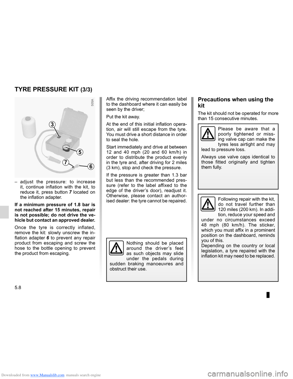
– adjust the pressure: to increase
it, continue inflation with the kit, to
reduce it, press button 7 located on
the inflation adapter.
If a minimum pressure of 1.8 bar is
not reached after 15 minutes, repair
is not possible; do not drive the ve-
hicle but contact an approved dealer.
Once the tyre is correctly inflated,
remove the kit: slowly unscrew the in -
flation adapter 6 to prevent any repair
product from escaping and screw the
hose to the bottle opening to prevent
the product from escaping.
Affix the driving recommendation label
to the dashboard where it can easily be
seen by the driver;
Put the kit away.
At the end of this initial inflation opera -
tion, air will still escape from the tyre.
You must drive a short distance in order
to seal the hole.
Start immediately and drive at between
12 and 40 mph (20 and 60 km/h) in
order to distribute the product evenly
in the tyre and, after driving for 2 miles
(3 km), stop and check the pressure.
If the pressure is greater than 1.3 bar
but less than the recommended pres -
sure (refer to the label affixed to the
edge of the driver’s door), readjust it.
Otherwise, please contact an author -
ised dealer: the tyre cannot be repaired.Precautions when using the
kit
The kit should not be operated for more
than 15 consecutive minutes.
3
5
7
Nothing should be placed
around the driver ’s feet
as such objects may slide
under the pedals during
sudden braking manoeuvres and
obstruct their use.
6
Please be aware that a
poorly tightened or miss -
ing valve cap can make the
tyres less airtight and may
lead to pressure loss.
Always use valve caps identical to
those fitted originally and tighten
them fully.
Following repair with the kit,
do not travel further than
120 miles (200 km). In addi -
tion, reduce your speed and
under no circumstances exceed
48 mph (80 km/h). The sticker,
which you must affix in a prominent
position on the dashboard, reminds
you of this.
Depending on the country or local
legislation, a tyre repaired with the
inflation kit may need to be replaced.
Page 201 of 268

Downloaded from www.Manualslib.com manuals search engine tool kit ................................................... (up to the end of the DU)
hubcap tool ........................................... (up to the end of the DU)
jack ....................................................... (up to the end of the DU)
wheelbrace ........................................... (up to the end of the DU)
towing hitch ........................................... (up to the end of the DU)
wheelbrace ........................................... (up to the end of the DU)
puncture ................................................ (up to the end of the DU)
5.9
ENG_UD19792_3
Bloc-outils (X85 - B85 - C85 - S85 - K85 - Renault)
ENG_NU_853-7_BCSK85_Renault_5
End piece for special wheel
bolt 3
Towing hitch 4
Refer to the information on “Towing” in
Section 5.
Hubcap tool 5 or 6This tool is used to remove the wheel
trims.
Jack 7Remove jack 7.
To refit, lower the jack fully and unscrew
it by one turn and pivot the base so that
it can be stored.
Storage compartment 1(depending on vehicle)
This is for storing a lock nut.
Wheelbrace 2This is used to tighten or release the
wheel bolts.
The tools included in the tool kit depend
on the vehicle.
Tool kit
A is located in the tray under
the luggage compartment carpet.
Depending on the vehicle, lift the cover,
then remove it.
Take out the tool kit, lifting it at both
ends.
To return it, proceed in the reverse
order to removal.
TOOL KIT
Tool kit
1
A
7
2
3
4
56
Do not leave the tools unsecured inside the vehicle as they may come loose under braking. After use, check that all the
tools are correctly clipped into the tool kit, then position it correctl\
y in its housing: there is a risk of injury.
If wheel bolts are supplied in the tool kit, only use these bolts for the emergency spare wheel: refer to the label affixed
to the emergency spare wheel.
The jack is designed for wheel changing purposes only. Under no circumstances should it be used for carrying out repairs un-
derneath the vehicle or to gain access to the underside of the vehicle.
Page 202 of 268
Downloaded from www.Manualslib.com manuals search engine hubcap tool ........................................... (up to the end of the DU)
trims ...................................................... (up to the end of the DU)
5.10
ENG_UD25542_2
Enjoliveur - Roue (X85 - B85 - C85 - S85 - K85 - Renault)
ENG_NU_853-7_BCSK85_Renault_5
Wheel trims - wheel
We would advise you to note down
the number engraved on the tool so
that you can replace it if it is lost.
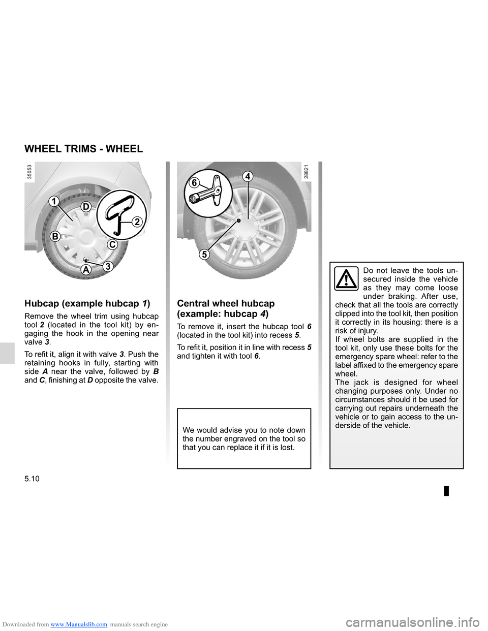
Central wheel hubcap
(example: hubcap 4)
To remove it, insert the hubcap tool 6
(located in the tool kit) into recess 5.
To refit it, position it in line with recess 5
and tighten it with tool 6.
Hubcap (example hubcap 1)
Remove the wheel trim using hubcap
tool 2 (located in the tool kit) by en -
gaging the hook in the opening near
valve 3.
To refit it, align it with valve 3. Push the
retaining hooks in fully, starting with
side A near the valve, followed by B
and C, finishing at D opposite the valve.
WHEEL TRIMS - WHEEL
4
5
6
Do not leave the tools un -
secured inside the vehicle
as they may come loose
under braking. After use,
check that all the tools are correctly
clipped into the tool kit, then position
it correctly in its housing: there is a
risk of injury.
If wheel bolts are supplied in the
tool kit, only use these bolts for the
emergency spare wheel: refer to the
label affixed to the emergency spare
wheel.
The jack is designed for wheel
changing purposes only. Under no
circumstances should it be used for
carrying out repairs underneath the
vehicle or to gain access to the un-
derside of the vehicle.
1
2
3A
B
D
C
Page 204 of 268
Downloaded from www.Manualslib.com manuals search engine 5.12
ENG_UD19793_3
Changement de roue (X85 - B85 - C85 - S85 - K85 - Renault)
ENG_NU_853-7_BCSK85_Renault_5
Anti-theft bolt
If you use anti-theft bolts, fit these
nearest the valve (otherwise it may
not be possible to fit the wheel trim).
If you have a puncture, re -
place the wheel as soon as
possible.
A tyre which has been punc-
tured should always be inspected
(and repaired, where possible) by a
specialist.
If the vehicle is parked on
the hard shoulder, you must
warn other road users of
your vehicle’s presence
with a warning triangle or with other
devices as per the legislation apply-
ing to the country you are in.
CHANGING A WHEEL (2/2)
Undo the bolts and take off the wheel.
Fit the emergency spare wheel on the
central hub and turn it to locate the
mounting holes in the wheel and the
hub.
Tighten the bolts and lower the jack.
With the wheel on the ground, tighten
the screws as fully as possible and
check the tightness as soon as possi -
ble (tightening torque 110 N.m).