stop start RENAULT DUSTER 2016 Owner's Manual
[x] Cancel search | Manufacturer: RENAULT, Model Year: 2016, Model line: DUSTER, Model: RENAULT DUSTER 2016Pages: 256, PDF Size: 6.49 MB
Page 96 of 256
2.20
MAINTENANCE AND ANTIPOLLUTION ADVICE
Your vehicle complies with criteria for
recycling and recovering vehicles at the
end of their service life, which will come
into force in 2015.
Some of the parts on your vehicle have
been designed to be recycled later.
These parts are easily removable in
order to be collected and reprocessed
in recycling networks.
Furthermore, by virtue of its design,
moderate fuel consumption and initial
settings, your vehicle also conforms
to current anti-pollution regulations.
The manufacturer is actively striving
to reduce pollutant exhaust gas emis-
sions and to save energy. However,
the fuel consumption of your vehicle
and the level of pollutant exhaust gas
emissions are also your responsibility.
Ensure that it is maintained and used
correctly.Maintenance
It is important to remember that fail-
ure to respect anti-pollution regulations
could lead to legal action being taken
against the vehicle owner.
In addition, replacing engine, fuel
supply system and exhaust compo-
nents with parts other than those origi-
nally recommended by the manufac-
turer may alter your vehicle so that it
no longer complies with anti-pollution
regulations.
Have your vehicle adjusted and
checked by an authorised dealer, in ac-
cordance with the instructions given in
your maintenance schedule: they will
have all the equipment necessary for
ensuring that your vehicle is maintained
to its original standard.
Engine adjustments
– Air filter, fuel filter: a choked ele-
ment will reduce efficiency. It must
be replaced.
– Idle speed: no adjustment is needed.
Exhaust gas monitoring
system
The exhaust gas monitoring system will
detect any operating faults in the vehi-
cle’s antipollution system.
If this system malfunctions, toxic sub-
stances may be released into the at-
mosphere or damage may occur.
ÄThis warning light on the in-
strument panel will indicate if
there are any faults in the system:
This lights up when the ignition is
switched on and goes out when the
engine is started.
– If it lights up continuously, consult an approved Dealer as soon as possi-
ble;
– if it flashes, reduce the engine speed until the light stops flashing. Contact
an authorised dealer as soon as pos-
sible.
Page 103 of 256
2.27
TYRE PRESSURE LOSS WARNING (6/7)
Note:
The standard tyre pressure cannot be
less than that recommended and indi-
cated on the door frame.
Display
Check tyre pressure
The warning light
comes on (not
flashing).
This indicates that at least one tyre is
flat.
Check and, if necessary, readjust the
pressures of the four wheels when cold.
The warning light
goes off after a
few minutes’ driving. Puncture
The warning light
and the red
warning light
Ò come on steady,
together with a beep.
They indicate that at least one wheel
is punctured or severely underinflated.
Replace it or contact an authorised
dealer if it is punctured. Top up the tyre
pressure if the wheel is deflated.
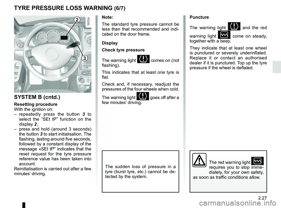
SYSTEM B (cntd.)
Resetting procedure
With the ignition on:
– repeatedly press the button 3 to
select the “SEt tP” function on the
display 2 ;
– press and hold (around 3 seconds) the button 3 to start initialisation. The
flashing, lasting around five seconds,
followed by a constant display of the
message «SEt tP" indicates that the
reset request for the tyre pressure
reference value has been taken into
account.
Reinitialisation is carried out after a few
minutes’ driving.
The sudden loss of pressure in a
tyre (burst tyre, etc.) cannot be de-
tected by the system.The red warning light Ò
requires you to stop imme-
diately, for your own safety,
as soon as traffic conditions allow.
2
3
Page 108 of 256
2.32
TRANSMISSION: 4-wheel drive (4WD) (3/4)
Electronic stability program and
traction control when driving off-
road
(vehicles equipped with ESC)
When driving on soft ground (sand,
mud, deep snow), we recommend that
you deactivate the ESC function by
pressing the “ ESC” switch.
In this case, only individual wheel bra-
king remains active. This function ap-
plies the brake to any wheel that is slip-
ping, allowing the engine torque to be
transferred to the wheels with the most
grip. This is particularly useful when
crossing a bridge.
All the ESC functions will be reactivated
when the vehicle speed reaches ap-
proximately 30 mph (50 km/h) (36 mph
(60 km/h) in 4WD Lock mode), when
the engine is restarted or when the
“ESC” button is pressed again.Operating faults
If the system detects an operating
fault, it automatically switches to “2WD”
mode, and the
‘ and Ò war-
ning lights come on.
Drive as soon as possible at a mode-
rate speed to an approved dealer.
For certain operating faults, the system
may not be able to switch to “2WD" or
"4WD Lock" mode. "AUTO" mode re-
mains active.
Contact an approved dealer as soon as
possible.
In this case, we recommend that you
stop as soon as possible to allow the
system to cool down (until the warning
light stops flashing).
Cooling may take up to five minutes.
If the system detects excessive whee-
lspin on the front wheels, it adapts the
engine to run in a way that reduces
wheelspin.
Anti-lock braking in “
LOCK” mode
(vehicles equipped with ABS)
When “4WD Lock" mode is active, the
ABS switches to off-road mode. In this
case, the wheels may lock intermit-
tently to achieve better grip, thus redu-
cing braking distances on soft ground.
When this mode is active:
– the vehicle’s manoeuvrability is limi- ted during braking. This operating
mode is therefore not recommended
in very low-grip conditions (eg. ice).
– there may be some noise. This is normal, and does not indicate an
operating fault.
Page 110 of 256

2.34
ABS (anti-lock braking
system)
Under heavy braking, the ABS prevents
the wheels from locking, allowing the
stopping distance to be managed and
keeping control of the vehicle. Under
these circumstances, the vehicle can
be steered to avoid an obstacle whilst
braking. In addition, this system can
increase stopping distances, particu-
larly on roads with low surface grip (wet
ground etc.).
You will feel a pulsation through the
brake pedal each time the system is
activated. The ABS does not in any way
improve the vehicle's physical perform-
ance relating to the road surface and
roadholding. It is still essential to follow
the rules of good driving practice (such
as driving at a safe distance from the
vehicle in front etc.).
DRIVER CORRECTION DEVICES/AIDS (1/4)
Depending on the vehicle, this is com-
posed of:
– the ABS (anti-lock braking
system);
– the emergency brake assist;
– electronic stability control (ESC)
with understeer control and trac-
tion control.
– hill start assistance.
These functions are an ad-
ditional aid in the event of
critical driving conditions,
enabling the vehicle behav-
iour to be adapted to suit the driving
conditions.
However, the functions do not take
the place of the driver. They do
not increase the vehicle’s limits
and should not encourage you
to drive more quickly. Therefore,
they can under no circumstances
replace the vigilance or responsibil-
ity of the driver when manoeuvring
the vehicle (the driver must always
be ready for sudden incidents which
may occur when driving).
In an emergency, apply firm and
continuous pressure to the brake
pedal. There is no need to pump
it repeatedly. The ABS will modu-
late the force applied in the braking
system.
Special feature of 4-wheel drive ve-
hicles
In 4WD Lock mode, the system may
lock the wheels briefly to optimise the
braking distance on very wet ground
(snow, mud, sand, etc.).
Page 113 of 256
2.37
DRIVER CORRECTION DEVICES/AIDS (4/4)
Hill start assistance
Depending on the gradient of the in-
cline, this system assists the driver
when starting on a hill. It prevents the
vehicle from rolling backwards by au-
tomatically applying the brakes when
the driver lifts his/her foot off the brake
pedal to depress the accelerator pedal.
It only operates when the gear lever is
in a position other than neutral (other
than N or P for automatic transmis-
sions) and the vehicle is completely
stationary (brake pedal depressed).
The system holds the vehicle for ap-
proximately 2 seconds. The brakes are
then released (the vehicle will move ac-
cording to the slope).
Operating principle
A sensor in the steering wheel detects
the direction selected by the driver.
Other sensors throughout the vehicle
measure the actual direction.
The system compares driver input to
the actual trajectory of the vehicle and
corrects the trajectory if necessary by
controlling the braking of certain wheels
and/or engine power. In the event that
the system is engaged, the indicator
light
flashes on the instrument
panel.
Operating faults
When the system detects an opera-
ting fault the warning lights
Ò and
appear on the instrument panel.
In this case, the Electronic Stability
Program ESC with understeer control
and traction control are deactivated.
Please consult an authorised dealer if
these warning lights remain displayed
on the instrument panel after the igni-
tion is switched off and on again.
The hill start assistance
system cannot completely
prevent the vehicle from
rolling backwards in all sit-
uations (extremely steep gradients
etc.).
In all cases, the driver may depress
the brake pedal to prevent the vehi-
cle from rolling backwards.
The hill start assistance function
should not be used for prolonged
stops: use the brake pedal.
This function is not designed to im-
mobilise the vehicle permanently.
If necessary, use the brake pedal to
stop the vehicle.
The driver must remain particularly
vigilant when driving on slippery or
low-grip surfaces and/or on hills.
Risk of serious injury.
Page 132 of 256
3.4
HEATING, VENTILATION, AIR CONDITIONING (1/3)
23415
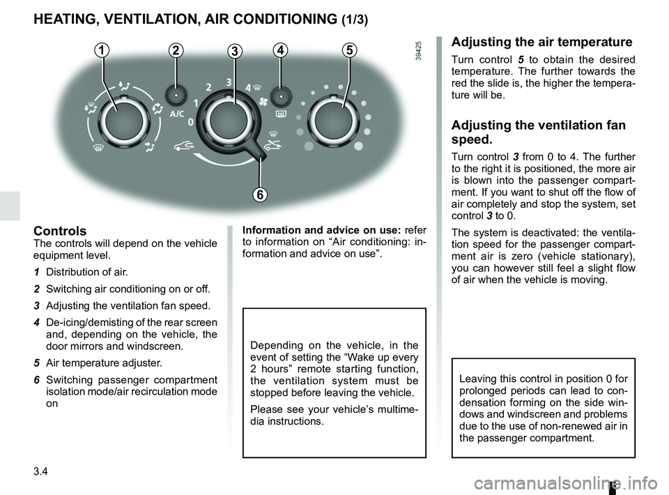
ControlsThe controls will depend on the vehicle
equipment level.
1 Distribution of air.
2 Switching air conditioning on or off.
3 Adjusting the ventilation fan speed.
4 De-icing/demisting of the rear screen and, depending on the vehicle, the
door mirrors and windscreen.
5 Air temperature adjuster.
6 Switching passenger compartment isolation mode/air recirculation mode
on
Adjusting the air temperature
Turn control 5 to obtain the desired
temperature. The further towards the
red the slide is, the higher the tempera-
ture will be.
Adjusting the ventilation fan
speed.
Turn control 3 from 0 to 4. The further
to the right it is positioned, the more air
is blown into the passenger compart-
ment. If you want to shut off the flow of
air completely and stop the system, set
control 3 to 0.
The system is deactivated: the ventila-
tion speed for the passenger compart-
ment air is zero (vehicle stationary),
you can however still feel a slight flow
of air when the vehicle is moving.
Leaving this control in position 0 for
prolonged periods can lead to con-
densation forming on the side win-
dows and windscreen and problems
due to the use of non-renewed air in
the passenger compartment.
6
Information and advice on use: refer
to information on “Air conditioning: in-
formation and advice on use”.
Depending on the vehicle, in the
event of setting the “Wake up every
2 hours” remote starting function,
the ventilation system must be
stopped before leaving the vehicle.
Please see your vehicle’s multime-
dia instructions.
Page 160 of 256
4.2
BONNET (1/2)
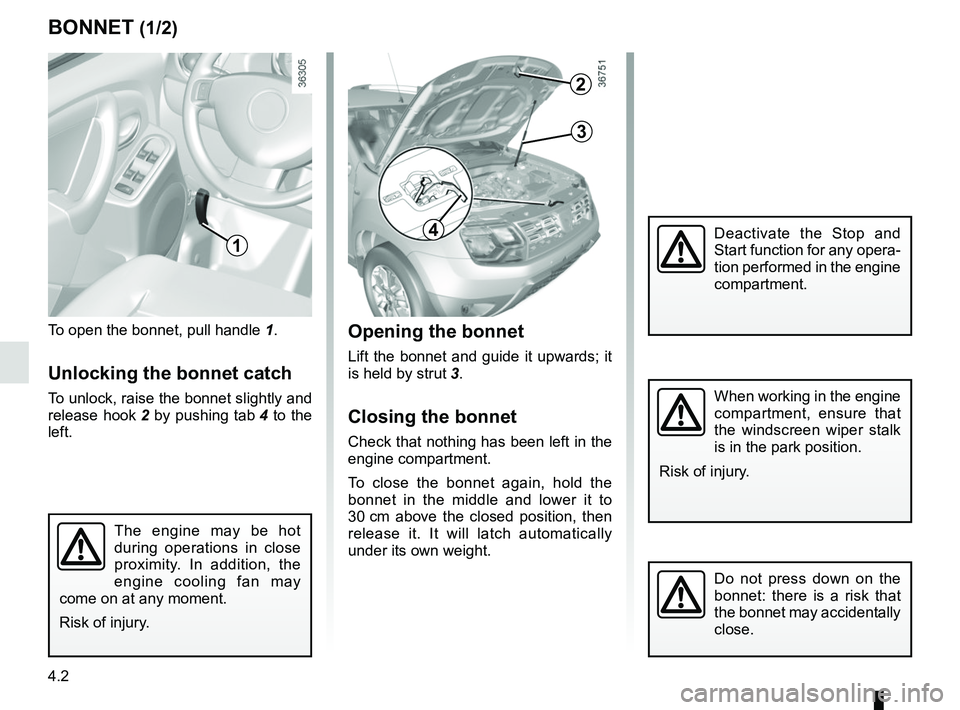
To open the bonnet, pull handle 1.
Unlocking the bonnet catch
To unlock, raise the bonnet slightly and
release hook 2 by pushing tab 4 to the
left.
Opening the bonnet
Lift the bonnet and guide it upwards; it
is held by strut 3.
Closing the bonnet
Check that nothing has been left in the
engine compartment.
To close the bonnet again, hold the
bonnet in the middle and lower it to
30 cm above the closed position, then
release it. It will latch automatically
under its own weight.
The engine may be hot
during operations in close
proximity. In addition, the
engine cooling fan may
come on at any moment.
Risk of injury.
Do not press down on the
bonnet: there is a risk that
the bonnet may accidentally
close.
1
When working in the engine
compartment, ensure that
the windscreen wiper stalk
is in the park position.
Risk of injury.
2
3
4Deactivate the Stop and
Start function for any opera-
tion performed in the engine
compartment.
Page 162 of 256
4.4
ENGINE OIL LEVEL: general information
Reading the oil levelThe oil level should be read with the ve-
hicle on level ground, after the engine
has been switched off for some time.
The dipstick must be used to read
the exact oil level and make sure
that the maximum level has not been
exceeded (risk of engine damage).
Refer to the following pages.
C
A
B
A
B
Exceeding the maximum
engine oil level
Under no circumstances
must the maximum fill
level B be exceeded: risk of damage
to the engine and catalytic con-
verter.
If the oil level exceeds the maximum
level, do not start your vehicle .
Contact an authorised dealer.
It is normal for an engine to use oil for
lubrication and cooling of moving parts
and it is normal to top up the level be-
tween oil changes.
However, contact your approved
Dealer if more than 0.5 litres is being
consumed every 600 miles (1,000 km)
after the running in period.
Oil change frequency: check the oil
level from time to time and certainly
before any long journey to avoid the
risk of damaging your engine.
Consult your approved dealer at
once if you notice an abnormal or
repeated drop in any of the fluid
levels.
In order to prevent splashback, it is
recommended that a funnel be used
when topping up/filling with oil.
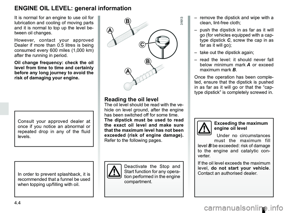
– remove the dipstick and wipe with a clean, lint-free cloth;
– push the dipstick in as far as it will go (for vehicles equipped with a cap-
type dipstick C, screw the cap in as
far as it will go);
– take out the dipstick again;
– read the level: it should never fall below minimum mark A or exceed
maximum mark B.
Once the operation has been comple-
ted, ensure that the dipstick is pushed
in as far as it will go or that the “cap-
type dipstick” is completely screwed in.
Deactivate the Stop and
Start function for any opera-
tion performed in the engine
compartment.
Page 165 of 256
4.7
ENGINE OIL LEVEL: topping up, filling (3/3)
Never run the engine in an
enclosed space as exhaust
gases are poisonous.
Resetting the alert after an oil
change
(depending on the vehicle)
If you change the oil yourself, you will
need to reset the oil change warning.
To do this, after switching on the igni-
tion, for ten seconds you must:
– Depress the accelerator pedal fully,
– with your foot on the accelerator, de-press the brake pedal three times in
succession.
Reinitialisation is complete when the
# indicator light goes out. If this is
not the case, repeat the operation.
Special case: if you change the oil
before the oil change interval exceeded
warning is displayed, it will also be nec-
essary to reset the display. In this case,
the
# warning light comes on for
approximately 5 seconds to confirm the
reset.
The engine may be hot
during operations in close
proximity. In addition, the
engine cooling fan may
come on at any moment.
Risk of injury.
Exceeding the maximum
engine oil level
Under no circumstances
must the maximum fill level
be exceeded: risk of damage to the
engine and catalytic converter.
If the oil level exceeds the maximum
level, do not start your vehicle .
Contact an authorised dealer.
Deactivate the Stop and
Start function for any opera-
tion performed in the engine
compartment.
Oil change
Service interval: refer to the
Maintenance Document for your vehi-
cle.
Oil change capacity
Please refer to the maintenance docu-
ment for your vehicle, or contact an au-
thorised dealer.
Always check the engine oil level using
the dipstick, as explained previously (it
should never fall below the minimum
level, or be over the maximum level on
the dipstick).
Engine oil grade
Refer to the Maintenance Document for
your vehicle.
Page 166 of 256
4.8
LEVELS (1/3)
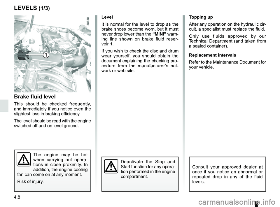
Brake fluid level
This should be checked frequently,
and immediately if you notice even the
slightest loss in braking efficiency.
The level should be read with the engine
switched off and on level ground. Level
It is normal for the level to drop as the
brake shoes become worn, but it must
never drop lower than the
“MINI” warn-
ing line shown on brake fluid reser-
voir 1.
If you wish to check the disc and drum
wear yourself, you should obtain the
document explaining the checking pro-
cedure from the manufacturer’s net-
work or web site. Topping up
After any operation on the hydraulic cir-
cuit, a specialist must replace the fluid.
Only use fluids approved by our
Technical Department (and taken from
a sealed container).
Replacement intervals
Refer to the Maintenance Document for
your vehicle.
The engine may be hot
when carrying out opera-
tions in close proximity. In
addition, the engine cooling
fan can come on at any moment.
Risk of injury.
Consult your approved dealer at
once if you notice an abnormal or
repeated drop in any of the fluid
levels.
1
Deactivate the Stop and
Start function for any opera-
tion performed in the engine
compartment.