ignition RENAULT KANGOO 1998 KC / 1.G Heating And Ventilation Workshop Manual
[x] Cancel search | Manufacturer: RENAULT, Model Year: 1998, Model line: KANGOO, Model: RENAULT KANGOO 1998 KC / 1.GPages: 73
Page 11 of 73
HEATING
Air distribution unit
61
PRO61.3
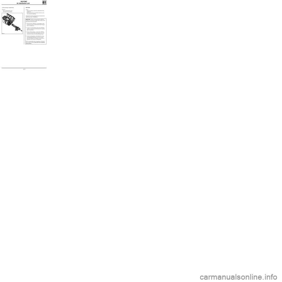
In the passenger compartment
Remove :
- the air distribution unit,
- the heater unit radiator.REFITTING
Check :
- that the wiring is correctly routed behind the
dashboard,
- that the air ducts are correctly secured to pre-
vent noises developing.
Change the steering wheel bolt (pre-bonded bolt,
tightening torque : 4.5 daN.m).
IMPORTANT : Before reconnecting the AIR BAG
cushion it is necessary to apply the air bag system
operational check procedure :
• Check that the AIR BAG warning light on the
instrument panel is illuminated when the igni-
tion is switched on.
• Connect an inert ignition unit to the AIR BAG
cushion connector and check that the warning
light extinguishes.
• Switch off the ignition, connect the AIR BAG
cushion in place of the inert ignition unit and
secure the cushion on to the steering wheel.
• Switch on the ignition, check that the air bag
warning light illuminates for three seconds
when the ignition is switched on and then ex-
tinguishes and remains extinguished.
If the warning light does not operate as indicated
above, please consult section 88 of the workshop
repair manual.
61-8
Page 16 of 73
c11010.0
AIR CONDITIONING
Fault finding - XR25 fiche
62
KANGOO
ALL TYPES
REPRESENTATION OF BARGRAPHS
REPRESENTATION OF FAULTS (always on a coloured background)
If illuminated, this indicates a fault on the component in question, the associated text defines
the fault.
REPRESENTATION OF STATUS (always on a white background)
Illuminates when dialogue is established with the component computer, if it remains
extinguished:
- the code does not exist,
- there is an equipment, computer or line fault.
Engine stopped, ignition on, no operator action
The status bargraphs on the fiche are represented as they should appear with the engine stopped, ignition
on and no operator action.
- If on the fiche, the bargraph is represented the XR25 should display
- If on the fiche, the bargraph is represented the XR25 should display
- If on the fiche, the bargraph is represented the XR25 should display
either or
Engine running
Extinguished when the function or condition described on the fiche is no longer carried out.
Illuminated when the function or condition described on the fiche is carried out.
62-5
Page 18 of 73
c11010.0
AIR CONDITIONING
Fault finding - Interpretation of XR25 bargraphs62
KANGOO
ALL TYPES
You may begin the fault finding procedure.AFTER
REPAIR
Right-hand bargraph 1 extinguished
XR25 / CONTROL UNIT COMMUNICATION
1
None.NOTES
Fiche n° 61
Before establishing communication between the XR25 and the control unit, check that you have switched
on the ignition.
Ensure that the XR25 is not the cause of the fault by trying to communicate with a computer on another
vehicle.
Check that the ISO interface is in position S8 and that you are using the latest version of the XR25 cassette
and the correct access code (D 17).
Check the battery voltage (U > 10.5 volts). Recharge the battery if necessary.
Check that the control unit connectors are engaged correctly.
Check that the air conditioning control unit is supplied correctly:
- earth on track 4 of the red 15-way connector
-+ after ignition on track 1 of the blue 30-way connector
-+ after ignition on track 6 of the red 15-way connector
-+ fuse board on track 5 of the red 15-way connector
Check that the diagnostic socket is supplied correctly:
track K track 6of the air conditioning control unit
track L track 3blue 30-way connector
If there is still no dialogue between the XR25 and the control unit, change the air conditioning control
unit.
62-7
Page 40 of 73
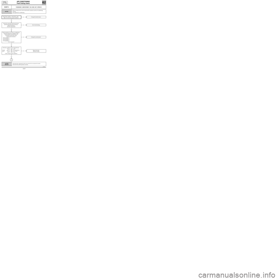
Check the condition of the wiring between:
B2 A2
control B3 A1 resistance
panel B4 C4 unit
B5 C1
Is the wiring in good condition?
yes
c11010.0
AIR CONDITIONING
Fault finding charts
62
KANGOO
ALL TYPES
AFTER
REPAIR
yes
CHART 9PASSENGER COMPARTMENT FAN DOES NOT OPERATE
NOTES
Check fuses +battery, +fuse board, +side
lights. Are the fuses in good condition?noChange the faulty fuse(s).
noEnd of fault finding.
yes
noChange the control panel.
yes
noRepair the faulty
electrical wiring.
A
Before carrying out any work, check that the customer uses the air conditioning
correctly.
Non regulated air conditioning.
Check the connections between the fuses
and the instrument panel connector.
Repair if necessary.
Does the fault persist?
With the ignition on and the air conditioning
selected, position the ventilation at the
various speeds and check that 12 V
is present on the tracks of the
control panel connector:
- B5 in position 1,
- B4 in position 2,
- B2 in position 3,
- B3 in position 4.
Is 12 V present?
Check that the components which were removed are connected correctly.
Check that the system operates correctly.
62-29
Page 43 of 73
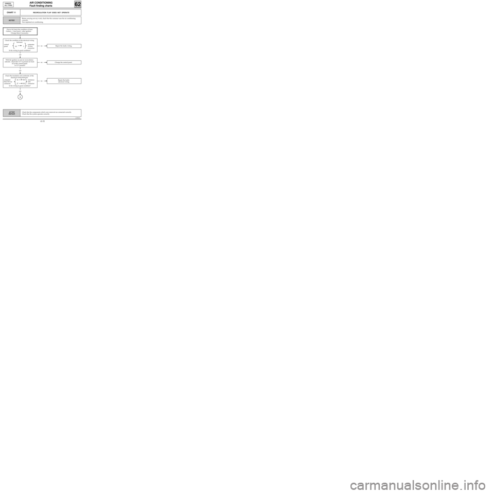
Check the insulation and continuity of the
electrical wiring between:
computer 26 B3 resistance
blue 30-way unit
connector 27 B2 connector
Is the wiring in good condition?
yes
Check the condition of the electrical wiring
between:
control computer
panel A2 3 15-way
connector
Is the wiring in good condition?
yes
c11010.0
AIR CONDITIONING
Fault finding charts
62
KANGOO
ALL TYPES
AFTER
REPAIR
CHART 11RECIRCULATION FLAP DOES NOT OPERATE
NOTES
noRepair the faulty wiring.
noChange the control panel.
noRepair the faulty
electrical wiring.
yes
A
Before carrying out any work, check that the customer uses the air conditioning
correctly.
Non regulated air conditioning.
First of all check the condition of fuses
+battery, + fuse board, +after ignition.
Change them if necessary.
With the ignition on and air recirculation
selected, check that 12 V is present on track
A2 of the control panel.
Is 12 V present?
Check that the components which were removed are connected correctly.
Check that the system operates correctly.
62-32
Page 72 of 73
AIR CONDITIONING
Computer
62
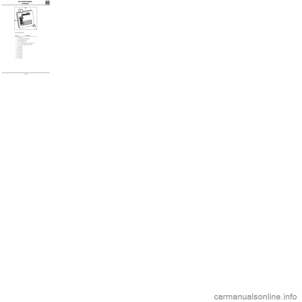
15-way connector (A)
13825R
Track Description
1 Not used
2 AC operating information
3 Recirculation on/off
4 AC computer earth
5 + 12 V accessories (fan assembly fuse)
6 + 12 V after ignition (brake fuse)
7 Not used
8 Not used
9 Not used
10 Not used
11 Not used
12 Not used
13 Not used
14 Not used
15 Not used
62-61
Page 73 of 73
AIR CONDITIONING
Computer
62
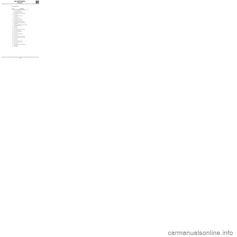
30-way connector (B)
Track Description
1 + 12 V after ignition (brake fuse)
2 Compressor control
3 L diagnostic information
4 Fan assembly voltage information
5 Not used
6 K diagnostic information
7 Not used
8 TDC information
9 Coolant pressure sensor
10 Coolant pressure sensor
11 Coolant pressure sensor signal
12Evaporator sensor (depending on
assembly)
13Power absorbed information (when the
compressor cuts in)
14 Not used
15 Not used
16 + 12 V after ignition (brake fuse)
17 Compressor control
18 AC cut off information
19 Not used
20 AC fast idle information
21 Not used
22 Fan assembly low speed control
23 Fan assembly high speed control
24 Not used
25 Not used
26 AC recirculation motor
27 AC recirculation motor
28 Not used
29Evaporator sensor (depending on
assembly)
30 Not used
62-62