wiring RENAULT KANGOO 1998 KC / 1.G Heating And Ventilation Workshop Manual
[x] Cancel search | Manufacturer: RENAULT, Model Year: 1998, Model line: KANGOO, Model: RENAULT KANGOO 1998 KC / 1.GPages: 73
Page 3 of 73

Contents
Pages
Heating and
Ventilation
Control panel
Control cables
Particle filter
Fan assembly (GMV)
Radiator
Air distribution unit61-1
61-2
61-3
61-4
61-5
61-6 HEATING
61
General
Fault finding - Introduction
Fault finding - XR25 fiche
Fault finding - Interpretation
of XR25 bargraphs
Fault finding - Customer complaints
Fault finding charts
Fault finding - Associated checks
Wiring diagram
Evaporator
Air blower unit
Compressor
Condenser
Pressure relief valve
Dehydration canister
Connecting pipes
Electrical control
Computer
62
62-1
62-3
62-4
62-6
62-18
62-19
62-43
62-44
62-48
62-50
62-51
62-54
62-55
62-56
62-57
62-60
62-61
AIR CONDITIONING
Page 9 of 73
HEATING
Air distribution unit
61
12969-1R
12965-1R
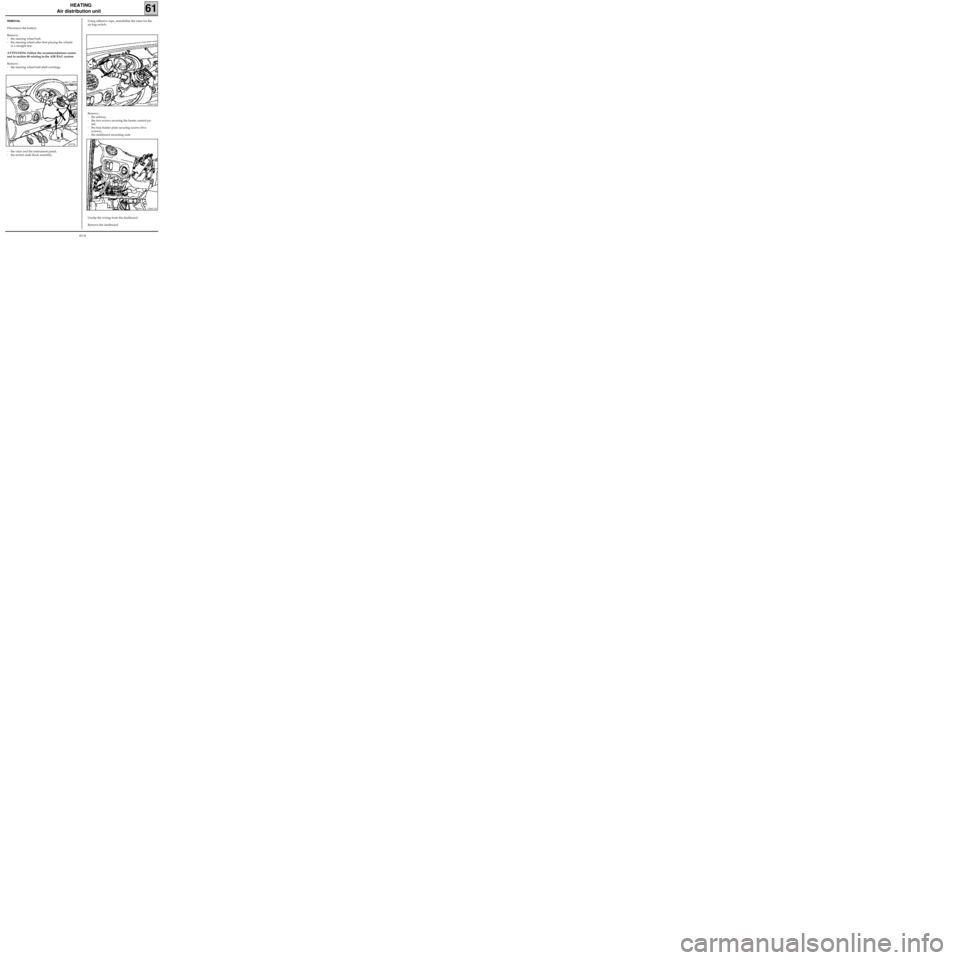
- the visor and the instrument panel,
- the switch stalk block assembly.
REMOVAL
Disconnect the battery.
Remove :
- the steering wheel bolt,
- the steering wheel after first placing the wheels
in a straight line.
ATTENTION: Follow the recommendations contai-
ned in section 88 relating to the AIR BAG system.
Remove :
- the steering wheel half-shell cowlings,Using adhesive tape, immobilise the rotor for the
air bag switch.
Remove :
- the ashtray,
- the two screws securing the heater control pa-
nel,
- the fuse holder plate securing screws (five
screws),
- the dashboard mounting nuts.
Unclip the wiring from the dashboard.
Remove the dashboard.
12971R
61-6
Page 11 of 73
HEATING
Air distribution unit
61
PRO61.3
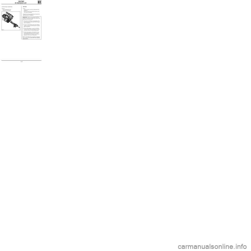
In the passenger compartment
Remove :
- the air distribution unit,
- the heater unit radiator.REFITTING
Check :
- that the wiring is correctly routed behind the
dashboard,
- that the air ducts are correctly secured to pre-
vent noises developing.
Change the steering wheel bolt (pre-bonded bolt,
tightening torque : 4.5 daN.m).
IMPORTANT : Before reconnecting the AIR BAG
cushion it is necessary to apply the air bag system
operational check procedure :
• Check that the AIR BAG warning light on the
instrument panel is illuminated when the igni-
tion is switched on.
• Connect an inert ignition unit to the AIR BAG
cushion connector and check that the warning
light extinguishes.
• Switch off the ignition, connect the AIR BAG
cushion in place of the inert ignition unit and
secure the cushion on to the steering wheel.
• Switch on the ignition, check that the air bag
warning light illuminates for three seconds
when the ignition is switched on and then ex-
tinguishes and remains extinguished.
If the warning light does not operate as indicated
above, please consult section 88 of the workshop
repair manual.
61-8
Page 19 of 73
c11010.0
AIR CONDITIONING
Fault finding - Interpretation of XR25 bargraphs62
KANGOO
ALL TYPES
Enter G0** on the XR25.
Check that the system operates correctly.AFTER
REPAIR
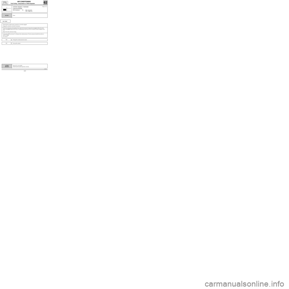
Left-hand bargraph 2 illuminated
COOLANT SENSOR
XR 25 assistance: *02 : 2 def = low level
1 def = high level
2
None.NOTES
Fiche n° 61
Low level
Check the continuity and insulation from earth of the electrical wiring between tracks A, B and C of the
sensor and tracks 9, 10 and 11 of the air conditioning control unit 30-way connector (sensor supplied with
5 V).
Repair the faulty electrical wiring.
Connect the XR25 and enter # 16. Measure the coolant pressure. The low pressure should be less than or
equal to 2 bars.
Is it correct?
Change the coolant pressure sensor.YES
NOTop up the coolant.
Check that the coolant sensor connector is correctly engaged.
Engage the connector correctly if necessary.
62-8
Page 20 of 73

c11010.0
AIR CONDITIONING
Fault finding - Interpretation of XR25 bargraphs62
KANGOO
ALL TYPES
Enter G0** on the XR25.
Check that the system operates correctly.AFTER
REPAIR
2
High level
Change the coolant pressure sensor.YES
NOTop up the coolant.
CONT
Check that the coolant sensor connector is correctly engaged.
Engage the connector correctly if necessary.
Check the condition of the electrical wiring between tracks A, B and C of the sensor and tracks 9, 10 and
11 of the air conditioning control unit 30-way connector (sensor supplied with 5 V).
Repair the faulty electrical wiring.
Connect the XR25 and enter # 16. Measure the coolant pressure. The high pressure should be less than or
equal to 28 bars.
Is it correct?
62-9
Page 22 of 73
c11010.0
AIR CONDITIONING
Fault finding - Interpretation of XR25 bargraphs62
KANGOO
ALL TYPES
Enter G0** on the XR25.
Check that the system operates correctly.AFTER
REPAIR
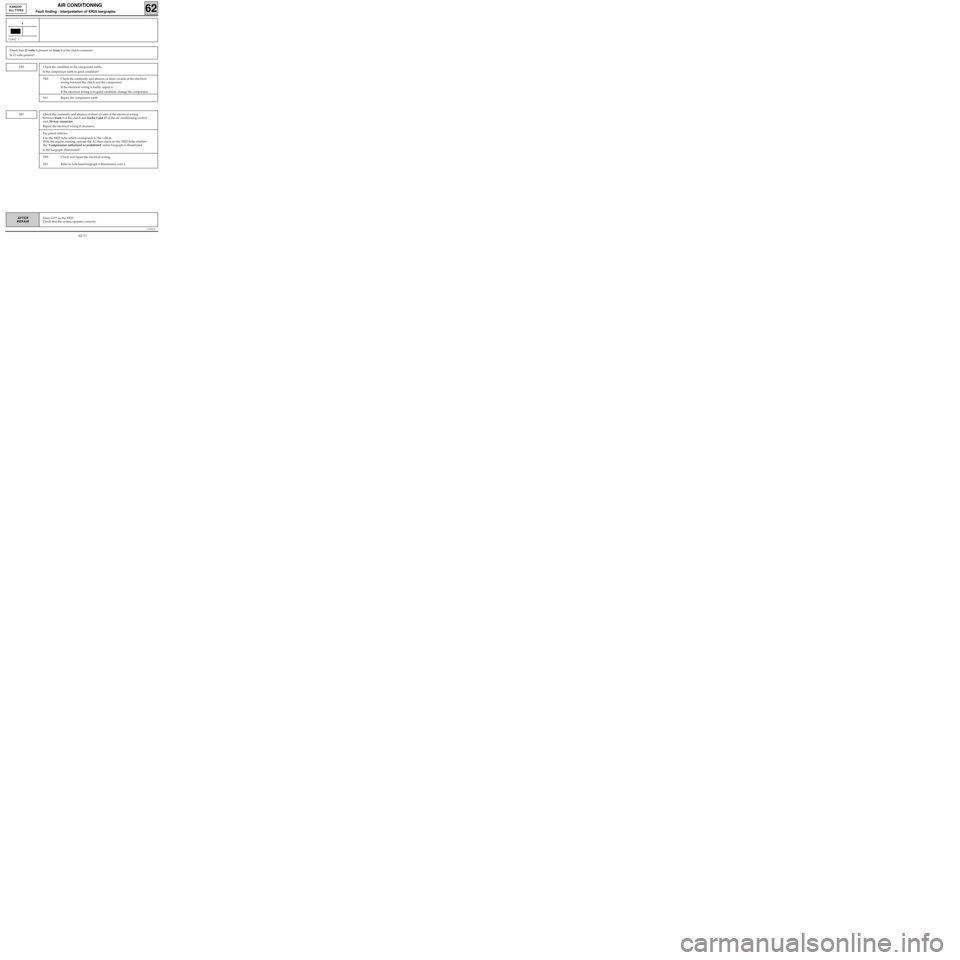
4
CONT 1
YES
NO
Check that 12 volts is present on track 1 of the clutch connector.
Is 12 volts present?
Check the condition of the compressor earth.
Is the compressor earth in good condition?
YES Check the continuity and absence of short circuits of the electrical
wiring between the clutch and the compressor.
If the electrical wiring is faulty, repair it.
If the electrical wiring is in good condition, change the compressor.
NO Repair the compressor earth.
Check the continuity and absence of short circuits of the electrical wiring
between track 1 of the clutch and tracks 2 and 17 of the air conditioning control
unit 30-way connector.
Repair the electrical wiring if necessary.
For petrol vehicles:
Use the XR25 fiche which corresponds to the vehicle.
With the engine running, operate the AC then check on the XR25 fiche whether
the "Compression authorised or prohibited" status bargraph is illuminated.
Is the bargraph illuminated?
YES Check and repair the electrical wiring.
NO Refer to Left-hand bargraph 4 illuminated, cont 2.
62-11
Page 23 of 73
c11010.0
AIR CONDITIONING
Fault finding - Interpretation of XR25 bargraphs62
KANGOO
ALL TYPES
Enter G0** on the XR25.
Check that the system operates correctly.AFTER
REPAIR
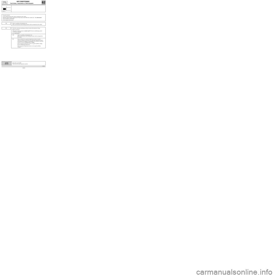
4
CONT 2
YES
NO
For petrol vehicles:
Use the XR25 injection fiche which corresponds to the vehicle.
With the engine running, operate the AC then check on the XR25 fiche whether the " AC authorisation"
status bargraph is illuminated.
Is the bargraph illuminated?
There is a problem at the injection end.
Refer to the injection fault finding procedure which corresponds to the vehicle.
Check the continuity and absence of short circuits of the electrical wiring.
Repair if necessary.
Check that 12 volts is present on tracks 2 and 17 of the air conditioning control
unit 30-way connector.
Is 12 volts present?
YES There is a problem at the injection end.
Refer to the injection fault finding procedure which corresponds to
the vehicle.
NO Check whether the evaporator temperature sensor is in place.
Check its resistance: disconnect the evaporator temperature sensor
and measure the resistance at its terminals. The resistance measured
should be between 90 ohms and 13.7 kohms.
If the evaporator temperature sensor is in good condition, change
the air conditioning control unit.
If the evaporator temperature sensor is not in good condition,
change it.
62-12
Page 24 of 73
Check the continuity and insulation from earth and from 12 volts of the electrical wiring between tracks:
air recirculation B2 27air conditioning control unit
motor connector B3 26 blue 30-way connector
Repair the faulty electrical wiring.
Check the condition of the electrical wiring between tracks:
control A2 3air conditioning control unit
panel red 15-way connector
Repair if necessary.
c11010.0
AIR CONDITIONING
Fault finding - Interpretation of XR25 bargraphs62
KANGOO
ALL TYPES
Enter G0** on the XR25.
Check that the system operates correctly.AFTER
REPAIR
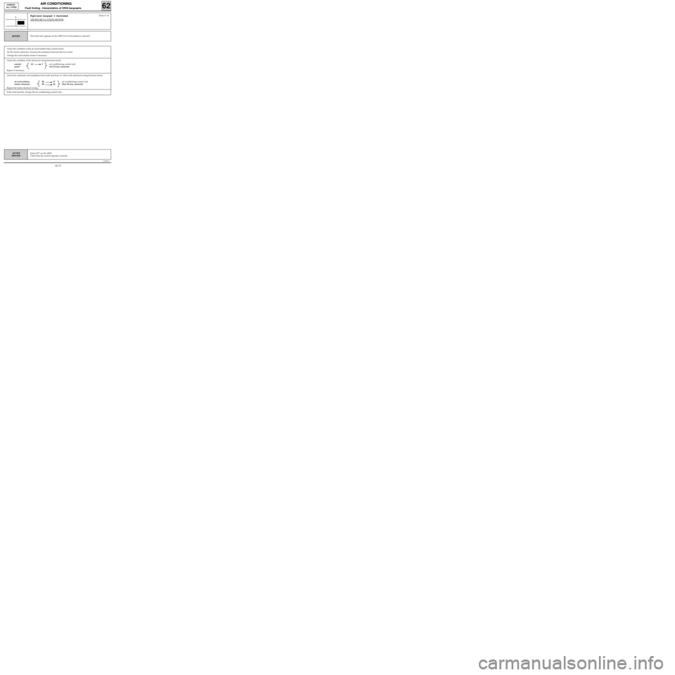
Right-hand bargraph 4 illuminated
AIR RECIRCULATION MOTOR
4
This fault only appears on the XR25 if air recirculation is selected.NOTES
Fiche n° 61
Check the condition of the air recirculation flap control motor.
On the motor connector, measure the resistance between the two tracks.
Change the recirculation motor if necessary.
If the fault persists, change the air conditioning control unit.
62-13
Page 25 of 73
c11010.0
AIR CONDITIONING
Fault finding - Interpretation of XR25 bargraphs62
KANGOO
ALL TYPES
Enter G0** on the XR25.
Check that the system operates correctly.AFTER
REPAIR
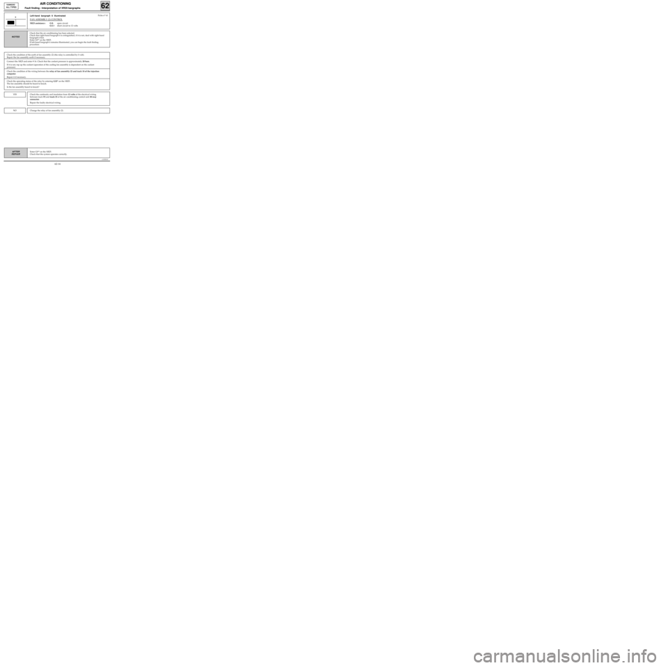
Left-hand bargraph 6 illuminated
FAN ASSEMBLY (2) CONTROL
XR25 assistance :C.O.open circuit
C.C.1short circuit to 12 volts
6
NOTES
Fiche n° 61
Check that the air conditioning has been selected.
Check that right-hand bargraph 6 is extinguished, if it is not, deal with right-hand
bargraph 6 first.
Enter G0** on the XR25.
If left-hand bargraph 6 remains illuminated, you can begin the fault finding
procedure.
Check the condition of the earth of fan assembly (2) (the relay is controlled by 0 volt).
Repair the fan assembly earth if necessary.
Connect the XR25 and enter # 16. Check that the coolant pressure is approximately 20 bars.
If it is not, top up the coolant (operation of the cooling fan assembly is dependent on the coolant
pressure).
NOChange the relay of fan assembly (2).
YESCheck the continuity and insulation from 12 volts of the electrical wiring
between track F2 and track 23 of the air conditioning control unit 30-way
connector.
Repair the faulty electrical wiring.
Check the condition of the wiring between the relay of fan assembly (2) and track 10 of the injection
computer.
Repair it if necessary.
Check the operating status of the relay by entering G23* on the XR25.
The fan assembly should be heard to knock.
Is the fan assembly heard to knock?
62-14
Page 26 of 73
c11010.0
AIR CONDITIONING
Fault finding - Interpretation of XR25 bargraphs62
KANGOO
ALL TYPES
Enter G0** on the XR25.
Check that the system operates correctly.AFTER
REPAIR
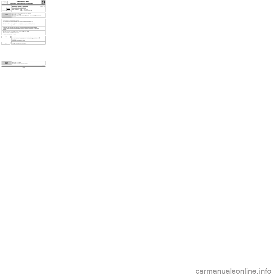
Right-hand bargraph 6 illuminated
FAN ASSEMBLY (1) CONTROL
XR25 assistance:C.O.open circuit
C.C.1short circuit to 12 volts
6
NOTES
Fiche n° 61
Check the condition of the earth of fan assembly (1) (the relay is controlled by 0 volt).
Repair the fan assembly earth if necessary.
Check that the air conditioning has been selected.
Enter G0** on the XR25.
If right-hand bargraph 6 remains illuminated, you can begin the fault finding
procedure.
Connect the XR25 and enter #16. Check that the coolant pressure is approximately 10 bars.
If it is not, top up the coolant (operation of the cooling fan assembly is dependent on the coolant
pressure).
Check that the air conditioning is operating.
Fan assembly (1) is controlled from the time the air conditioning is switched on.
Check the operating status of the relay by entering G22* on the XR25.
The fan assembly should be heard to knock.
Is the fan assembly heard to knock?
YES
Change the relay of fan assembly (1).NO
Check the continuity and insulation from 12 volts of the electrical wiring
between track M2 and track 22 of the air conditioning control unit 30-way
connector.
Repair the faulty electrical wiring.
62-15