wiring RENAULT KANGOO 2013 X61 / 2.G Air Bags AC4 And Pretensioners Workshop Manual
[x] Cancel search | Manufacturer: RENAULT, Model Year: 2013, Model line: KANGOO, Model: RENAULT KANGOO 2013 X61 / 2.GPages: 40, PDF Size: 0.55 MB
Page 2 of 40
88C-2V1 MR-376-X76-88C000$010.mif
88C
2nd generation
(AC4 phase II)
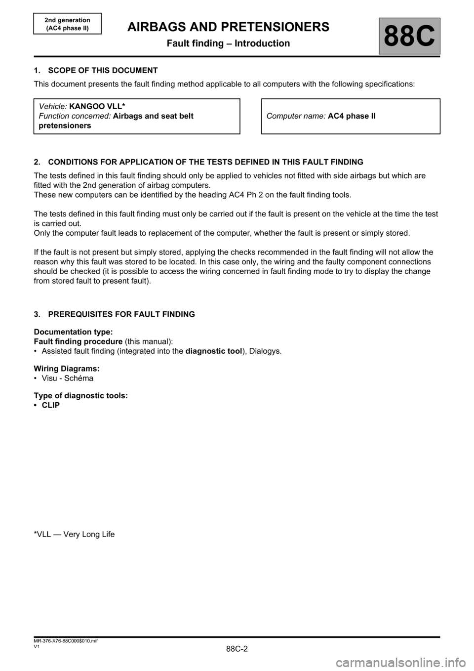
1. SCOPE OF THIS DOCUMENT
This document presents the fault finding method applicable to all computers with the following specifications:
2. CONDITIONS FOR APPLICATION OF THE TESTS DEFINED IN THIS FAULT FINDING
The tests defined in this fault finding should only be applied to vehicles not fitted with side airbags but which are
fitted with the 2nd generation of airbag computers.
These new computers can be identified by the heading AC4 Ph 2 on the fault finding tools.
The tests defined in this fault finding must only be carried out if the fault is present on the vehicle at the time the test
is carried out.
Only the computer fault leads to replacement of the computer, whether the fault is present or simply stored.
If the fault is not present but simply stored, applying the checks recommended in the fault finding will not allow the
reason why this fault was stored to be located. In this case only, the wiring and the faulty component connections
should be checked (it is possible to access the wiring concerned in fault finding mode to try to display the change
from stored fault to present fault).
3. PREREQUISITES FOR FAULT FINDING
Documentation type:
Fault finding procedure (this manual):
• Assisted fault finding (integrated into the diagnostic tool), Dialogys.
Wiring Diagrams:
•Visu - Schéma
Type of diagnostic tools:
•CLIP
*VLL — Very Long LifeVehicle: KANGOO VLL*
Function concerned: Airbags and seat belt
pretensionersComputer name: AC4 phase II
AIRBAGS AND PRETENSIONERS
Fault finding – Introduction
Page 3 of 40
88C-3V1 MR-376-X76-88C000$010.mif
AIRBAGS AND PRETENSIONERS
Fault finding – Introduction88C
2nd generation
(AC4 phase II)
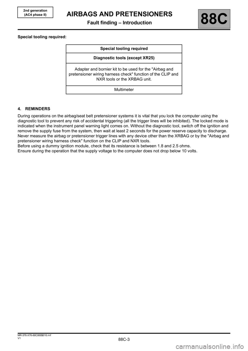
Special tooling required:
4. REMINDERS
During operations on the airbag/seat belt pretensioner systems it is vital that you lock the computer using the
diagnostic tool to prevent any risk of accidental triggering (all the trigger lines will be inhibited). The locked mode is
indicated when the instrument panel warning light comes on. Without the diagnostic tool, switch off the ignition and
remove the supply fuse from the system, then wait at least 2 seconds for the power reserve capacity to discharge.
Never measure the airbag or pretensioner trigger lines with any device other than the XRBAG or by the "Airbag and
pretensioner wiring harness check" function on the CLIP and NXR tools.
Before using a dummy ignition module, check that its resistance is between 1.8 and 2.5 ohms.
Ensure during the operation that the supply voltage to the computer does not drop below 10 volts.Special tooling required
Diagnostic tools (except XR25)
Adapter and bornier kit to be used for the "Airbag and
pretensioner wiring harness check" function of the CLIP and
NXR tools or the XRBAG unit.
Multimeter
Page 6 of 40
88C-6V1 MR-376-X76-88C000$010.mif
AIRBAGS AND PRETENSIONERS
Fault finding – Introduction88C
2nd generation
(AC4 phase II)
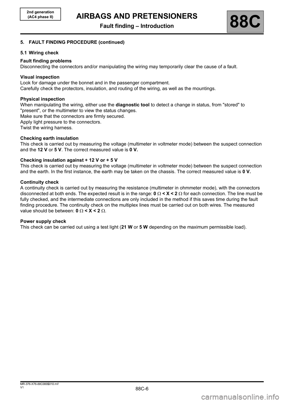
5. FAULT FINDING PROCEDURE (continued)
5.1 Wiring check
Fault finding problems
Disconnecting the connectors and/or manipulating the wiring may temporarily clear the cause of a fault.
Visual inspection
Look for damage under the bonnet and in the passenger compartment.
Carefully check the protectors, insulation, and routing of the wiring, as well as the mountings.
Physical inspection
When manipulating the wiring, either use the diagnostic tool to detect a change in status, from "stored" to
"present", or the multimeter to view the status changes.
Make sure that the connectors are firmly secured.
Apply light pressure to the connectors.
Twist the wiring harness.
Checking earth insulation
This check is carried out by measuring the voltage (multimeter in voltmeter mode) between the suspect connection
and the 12 V or 5V. The correct measured value is 0V.
Checking insulation against + 12 V or + 5 V
This check is carried out by measuring the voltage (multimeter in voltmeter mode) between the suspect connection
and the earth. In the first instance, the earth may be taken on the chassis. The correct measured value is 0V.
Continuity check
A continuity check is carried out by measuring the resistance (multimeter in ohmmeter mode), with the connectors
disconnected at both ends. The expected result is in the range: 0 < X < 2 for each connection. The line must be
fully checked, and the intermediate connections are only included in the method if this saves time during the fault
finding procedure. The continuity check on the multiplex lines must be carried out on both wires. The measured
value should be between: 0 < X < 2 .
Power supply check
This check can be carried out using a test light (21 W or 5 W depending on the maximum permissible load).
Page 7 of 40
88C-7V1 MR-376-X76-88C000$010.mif
AIRBAGS AND PRETENSIONERS
Fault finding – Introduction88C
2nd generation
(AC4 phase II)
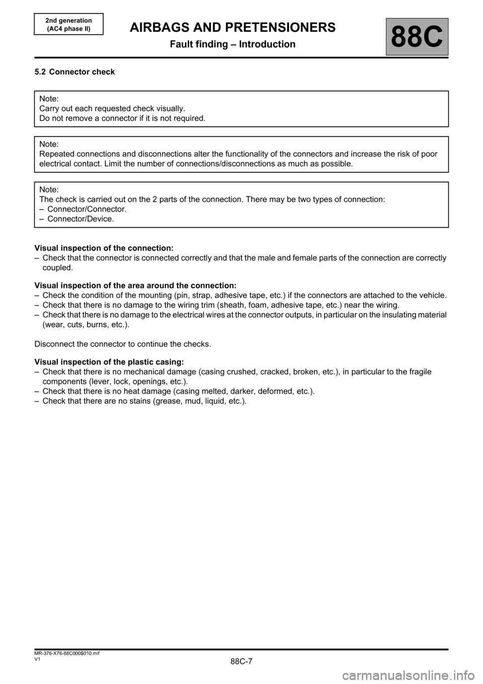
5.2 Connector check
Visual inspection of the connection:
– Check that the connector is connected correctly and that the male and female parts of the connection are correctly
coupled.
Visual inspection of the area around the connection:
– Check the condition of the mounting (pin, strap, adhesive tape, etc.) if the connectors are attached to the vehicle.
– Check that there is no damage to the wiring trim (sheath, foam, adhesive tape, etc.) near the wiring.
– Check that there is no damage to the electrical wires at the connector outputs, in particular on the insulating material
(wear, cuts, burns, etc.).
Disconnect the connector to continue the checks.
Visual inspection of the plastic casing:
– Check that there is no mechanical damage (casing crushed, cracked, broken, etc.), in particular to the fragile
components (lever, lock, openings, etc.).
– Check that there is no heat damage (casing melted, darker, deformed, etc.).
– Check that there are no stains (grease, mud, liquid, etc.).Note:
Carry out each requested check visually.
Do not remove a connector if it is not required.
Note:
Repeated connections and disconnections alter the functionality of the connectors and increase the risk of poor
electrical contact. Limit the number of connections/disconnections as much as possible.
Note:
The check is carried out on the 2 parts of the connection. There may be two types of connection:
– Connector/Connector.
– Connector/Device.
Page 8 of 40
88C-8V1 MR-376-X76-88C000$010.mif
AIRBAGS AND PRETENSIONERS
Fault finding – Introduction88C
2nd generation
(AC4 phase II)
• Visual inspection of the metal contacts:
(The female contact is called CLIP. The male contact is called TAB.)
– Check that there are no bent contacts (the contact is not inserted correctly and can come out of the back of the
connector). The contact comes out of the connector when the wire is pulled gently.
– Check that there is no damage (folded tabs, clips open too wide, blackened or melted contact, etc.).
– Check that there is no oxidation on the metal contacts.
• Visual inspection of the sealing:
(Only for watertight connectors)
Check for the seal on the connection (between the 2 parts of the connection).
– Check the seal at the back of the connectors:
– For unit joints (1 for each wire), check that the unit joints are present on each electrical wire and that they
are correctly positioned in the opening (level with the housing). Check that plugs are present on openings
which are not used.
– For a grommet seal (one seal which covers the entire internal surface of the connector), check that the seal
is present.
– For gel seals, check for gel in all of the openings without removing the excess or any protruding sections (it
does not matter if there is gel on the contacts).
– For hotmelt sealing (heat-shrink sheath with glue), check that the sheath has contracted correctly on the
rear of the connectors and electrical wires, and that the hardened glue comes out of the side of the wire.
– Check that there is no damage to any of the seals (cuts, burns, significant deformation, etc.).
If a fault is detected, consult Technical Note 6015A, Repairing electrical wiring.
Page 15 of 40
88C-15
AFTER REPAIRDeal with any faults displayed by the diagnostic tool.
Clear the computer memory.
Carry out a road test followed by another check with the diagnostic tool.
V1 MR-376-X76-88C000$060.mif
88C
2nd generation
(AC4 phase II)
DF001
PRESENT
OR
STOREDCOMPUTER
1.DEF: Internal electronic fault
2.DEF: Impact detected
NOTESUse Wiring Diagrams Technical Note for Kangoo VLL.
Replace the airbag computer, component code 756 (consult the section "Replacement of components" for this
operation) (see MR Mechanical: MR-AIRBAGS-SRP, 88, Airbags and seat belt pretensioners, Computer:
Removal-refitting).
AIRBAGS AND PRETENSIONERS
Fault finding – Interpretation of faults
Page 16 of 40
88C-16
AFTER REPAIRDeal with any faults displayed by the diagnostic tool.
Clear the computer memory.
Carry out a road test followed by another check with the diagnostic tool.
V1 MR-376-X76-88C000$060.mif
AIRBAGS AND PRETENSIONERS
Fault finding – Interpretation of faults88C
2nd generation
(AC4 phase II)
DF002
PRESENT
OR
STOREDCOMPUTER SUPPLY VOLTAGE
1.DEF: Too many micro-breaks
2.DEF: Supply voltage too low
NOTESUse the B40 30-track adapter to work on the computer connector.
Use Wiring Diagrams Technical Note for Kangoo VLL.
1.DEF
2.DEF
NOTESNone.
Carry out the operations necessary to obtain the correct computer supply voltage:
10.5 volts ± 0.1 < correct voltage < 16 volts ± 0.1.
– Battery charge check.
– Charging circuit check.
– Check the tightness and condition of the battery terminals.
– Computer earth check.
– Check the condition of the + computer locking connections.
Page 17 of 40
88C-17
AFTER REPAIRDeal with any faults displayed by the diagnostic tool.
Clear the computer memory.
Carry out a road test followed by another check with the diagnostic tool.
V1 MR-376-X76-88C000$060.mif
AIRBAGS AND PRETENSIONERS
Fault finding – Interpretation of faults88C
2nd generation
(AC4 phase II)
DF003
PRESENT
OR
STOREDDRIVER'S FRONTAL AIRBAG CIRCUITCC: Short circuit
CO: Open circuit
CC.1: Short circuit to 12 volts
CC.0: Short circuit to earth
NOTESNever carry out measuring operations on ignition lines using any tool other than Clip,
NXR or XRBAG.
Use Wiring Diagrams Technical Note for Kangoo VLL.
CO
CC
NOTESNone.
Lock the computer using the command on the diagnostic tool.
Switch off the ignition and remove the 2 mounting bolts from the steering wheel cushion.
Check that it is correctly connected.
Disconnect the steering wheel airbag and connect a dummy ignition module to the ignition module connector.
Switch on the ignition and carry out a check using the diagnostic tool.
Replace the airbag if the fault is now stored (fault no longer declared as present) (see MR Mechanical: MR-
AIRBAGS-SRP, 88, Airbags and seat belt pretensioners, Driver's airbag: Removal-refitting).
With the ignition switched off, disconnect and reconnect the connector of the rotary contact beneath the steering
wheel.
Check the connections if the fault has become stored (fault no longer declared present).
Page 18 of 40
88C-18
AFTER REPAIRDeal with any faults displayed by the diagnostic tool.
Clear the computer memory.
Carry out a road test followed by another check with the diagnostic tool.
V1 MR-376-X76-88C000$060.mif
AIRBAGS AND PRETENSIONERS
Fault finding – Interpretation of faults88C
2nd generation
(AC4 phase II)
DF003
CONTINUED 1
The CLIP, NXR or XRBAG tools must be used for checking the resistance at point C2 of the driver's front airbag
circuit.
If the value obtained is incorrect, replace the rotary switch under the steering wheel.
Reconnect the rotary switch under the steering wheel, disconnect the computer connector and fit the B40 30-track
adapter.
The CLIP, NXR or XRBAG tool must be used to measure the resistance on the adapter cable marked A.
If the value obtained is not correct, check the connections of the 30-track connector (tracks 10 and 11) and replace
the wiring if necessary.
If the checks carried out have not shown the presence of a fault, check on the base of the airbag computer for the
presence of the 5 shunt opening pins for the 30-track connector.
Check the condition of the computer connections.
Check the condition of the 30-track connector (locking system, etc.).
Page 19 of 40
88C-19
AFTER REPAIRDeal with any faults displayed by the diagnostic tool.
Clear the computer memory.
Carry out a road test followed by another check with the diagnostic tool.
V1 MR-376-X76-88C000$060.mif
AIRBAGS AND PRETENSIONERS
Fault finding – Interpretation of faults88C
2nd generation
(AC4 phase II)
DF003
CONTINUED 2
CC.1
CC.0NOTESNone.
Lock the computer using the command on the diagnostic tool.
Switch off the ignition and remove the 2 mounting bolts from the steering wheel cushion.
Check the condition of the trigger wire.
The CLIP, NXR or XRBAG tools must be used for measuring the insulation appropriate to the type of fault at point
C2 of the driver's front airbag circuit.
If the value obtained is incorrect, replace the rotary switch under the steering wheel.
Reconnect the rotary switch under the steering wheel, disconnect the computer connector and fit the B40 30-track
adapter.
The CLIP, NXR or XRBAG tools must be used for measuring the insulation appropriate to the type of fault on the
cable marked A on the adapter.
If the value obtained is not correct, check the connections of the 30-track connector (tracks 10 and 11) and replace
the wiring if necessary.