crankshaft RENAULT KANGOO 2013 X61 / 2.G Diesel DCM 1.2 Injection Workshop Manual
[x] Cancel search | Manufacturer: RENAULT, Model Year: 2013, Model line: KANGOO, Model: RENAULT KANGOO 2013 X61 / 2.GPages: 204, PDF Size: 0.99 MB
Page 10 of 204
13B-10V1 MR-376-X76-13B000$030.mif
13B
DCM 1.2 Injection
Program no.: 4C
Vdiag No.: 08
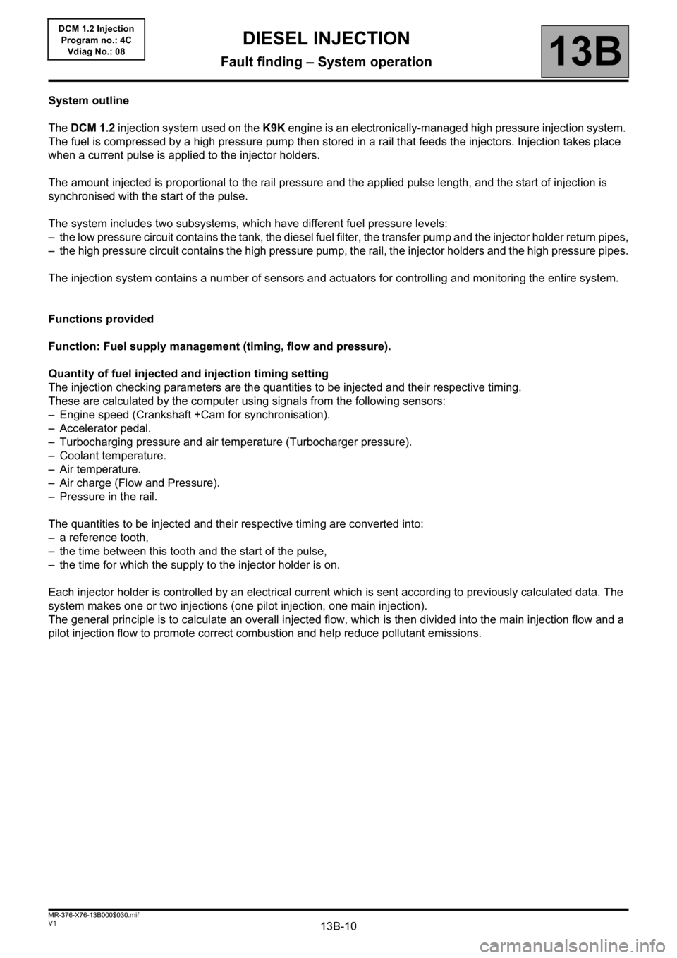
System outline
The DCM 1.2 injection system used on the K9K engine is an electronically-managed high pressure injection system.
The fuel is compressed by a high pressure pump then stored in a rail that feeds the injectors. Injection takes place
when a current pulse is applied to the injector holders.
The amount injected is proportional to the rail pressure and the applied pulse length, and the start of injection is
synchronised with the start of the pulse.
The system includes two subsystems, which have different fuel pressure levels:
– the low pressure circuit contains the tank, the diesel fuel filter, the transfer pump and the injector holder return pipes,
– the high pressure circuit contains the high pressure pump, the rail, the injector holders and the high pressure pipes.
The injection system contains a number of sensors and actuators for controlling and monitoring the entire system.
Functions provided
Function: Fuel supply management (timing, flow and pressure).
Quantity of fuel injected and injection timing setting
The injection checking parameters are the quantities to be injected and their respective timing.
These are calculated by the computer using signals from the following sensors:
– Engine speed (Crankshaft +Cam for synchronisation).
– Accelerator pedal.
– Turbocharging pressure and air temperature (Turbocharger pressure).
– Coolant temperature.
– Air temperature.
– Air charge (Flow and Pressure).
– Pressure in the rail.
The quantities to be injected and their respective timing are converted into:
– a reference tooth,
– the time between this tooth and the start of the pulse,
– the time for which the supply to the injector holder is on.
Each injector holder is controlled by an electrical current which is sent according to previously calculated data. The
system makes one or two injections (one pilot injection, one main injection).
The general principle is to calculate an overall injected flow, which is then divided into the main injection flow and a
pilot injection flow to promote correct combustion and help reduce pollutant emissions.
DIESEL INJECTION
Fault finding – System operation
Page 29 of 204
13B-29
AFTER REPAIRDeal with any faults declared by the diagnostic tool.
Clear the computer memory.
Carry out a road test followed by another check with the diagnostic tool.
V1 MR-376-X76-13B000$071.mif
DIESEL INJECTION
Fault finding – Interpretation of faults13B
DCM 1.2 Injection
Program no.: 4C
Vdiag No.: 08
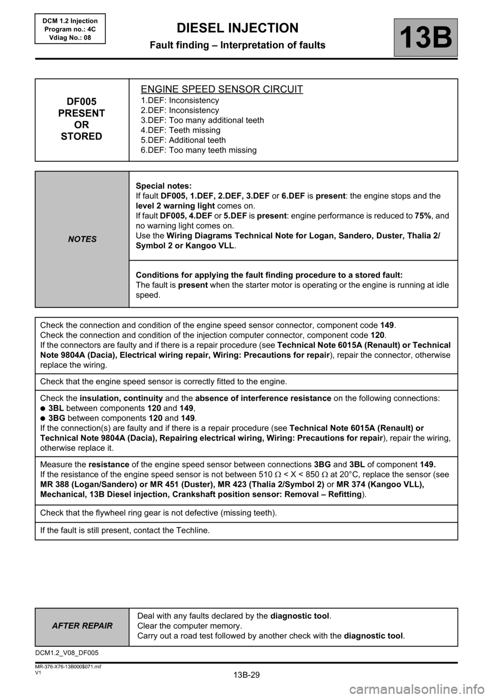
DF005
PRESENT
OR
STOREDENGINE SPEED SENSOR CIRCUIT1.DEF: Inconsistency
2.DEF: Inconsistency
3.DEF: Too many additional teeth
4.DEF: Teeth missing
5.DEF: Additional teeth
6.DEF: Too many teeth missing
NOTESSpecial notes:
If fault DF005, 1.DEF, 2.DEF, 3.DEF or 6.DEF is present: the engine stops and the
level 2 warning light comes on.
If fault DF005, 4.DEF or 5.DEF is present: engine performance is reduced to 75%, and
no warning light comes on.
Use the Wiring Diagrams Technical Note for Logan, Sandero, Duster, Thalia 2/
Symbol 2 or Kangoo VLL.
Conditions for applying the fault finding procedure to a stored fault:
The fault is present when the starter motor is operating or the engine is running at idle
speed.
Check the connection and condition of the engine speed sensor connector, component code 149.
Check the connection and condition of the injection computer connector, component code 120.
If the connectors are faulty and if there is a repair procedure (see Technical Note 6015A (Renault) or Technical
Note 9804A (Dacia), Electrical wiring repair, Wiring: Precautions for repair), repair the connector, otherwise
replace the wiring.
Check that the engine speed sensor is correctly fitted to the engine.
Check the insulation, continuity and the absence of interference resistance on the following connections:
●3BL between components 120 and 149,
●3BG between components 120 and 149.
If the connection(s) are faulty and if there is a repair procedure (see Technical Note 6015A (Renault) or
Technical Note 9804A (Dacia), Repairing electrical wiring, Wiring: Precautions for repair), repair the wiring,
otherwise replace it.
Measure the resistance of the engine speed sensor between connections 3BG and 3BL of component 149.
If the resistance of the engine speed sensor is not between 510 < X < 850 at 20°C, replace the sensor (see
MR 388 (Logan/Sandero) or MR 451 (Duster), MR 423 (Thalia 2/Symbol 2) or MR 374 (Kangoo VLL),
Mechanical, 13B Diesel injection, Crankshaft position sensor: Removal – Refitting).
Check that the flywheel ring gear is not defective (missing teeth).
If the fault is still present, contact the Techline.
DCM1.2_V08_DF005
Page 102 of 204
13B-102
AFTER
REPAIRDeal with any faults declared by the diagnostic tool.
Clear the computer memory.
Carry out a road test followed by another check with the diagnostic tool.
V1 MR-376-X76-13B000$072.mif
DIESEL INJECTION
Fault finding – Interpretation of faults13B
DCM 1.2 Injection
Program no.: 4C
Vdiag No.: 08
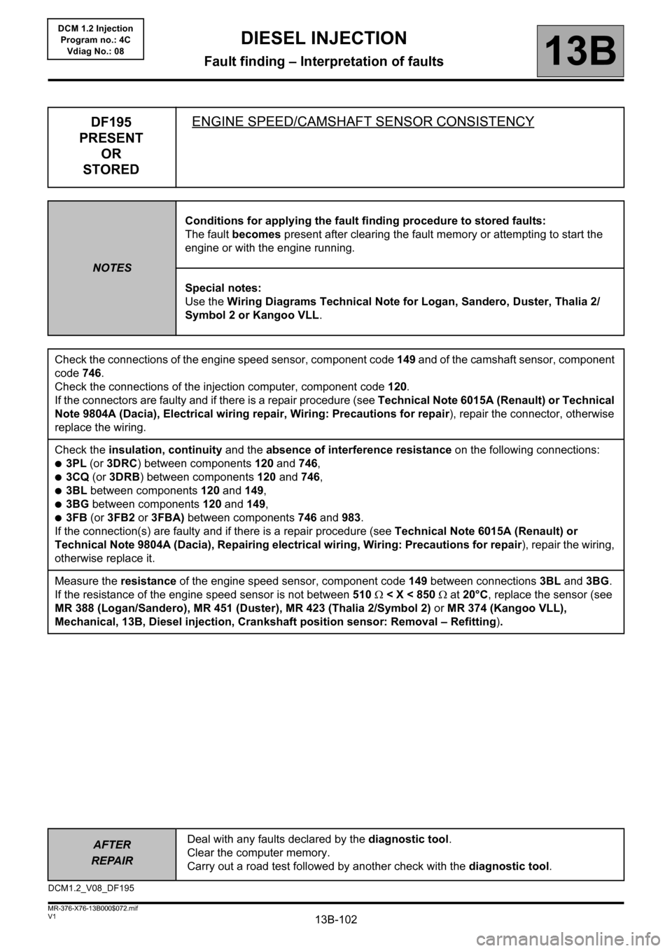
DF195
PRESENT
OR
STOREDENGINE SPEED/CAMSHAFT SENSOR CONSISTENCY
NOTESConditions for applying the fault finding procedure to stored faults:
The fault becomes present after clearing the fault memory or attempting to start the
engine or with the engine running.
Special notes:
Use the Wiring Diagrams Technical Note for Logan, Sandero, Duster, Thalia 2/
Symbol 2 or Kangoo VLL.
Check the connections of the engine speed sensor, component code 149 and of the camshaft sensor, component
code 746.
Check the connections of the injection computer, component code 120.
If the connectors are faulty and if there is a repair procedure (see Technical Note 6015A (Renault) or Technical
Note 9804A (Dacia), Electrical wiring repair, Wiring: Precautions for repair), repair the connector, otherwise
replace the wiring.
Check the insulation, continuity and the absence of interference resistance on the following connections:
●3PL (or 3DRC) between components 120 and 746,
●3CQ (or 3DRB) between components 120 and 746,
●3BL between components 120 and 149,
●3BG between components 120 and 149,
●3FB (or 3FB2 or 3FBA) between components 746 and 983.
If the connection(s) are faulty and if there is a repair procedure (see Technical Note 6015A (Renault) or
Technical Note 9804A (Dacia), Repairing electrical wiring, Wiring: Precautions for repair), repair the wiring,
otherwise replace it.
Measure the resistance of the engine speed sensor, component code 149 between connections 3BL and 3BG.
If the resistance of the engine speed sensor is not between 510 < X < 850 at 20°C, replace the sensor (see
MR 388 (Logan/Sandero), MR 451 (Duster), MR 423 (Thalia 2/Symbol 2) or MR 374 (Kangoo VLL),
Mechanical, 13B, Diesel injection, Crankshaft position sensor: Removal – Refitting).
DCM1.2_V08_DF195
Page 108 of 204
13B-108
AFTER
REPAIRDeal with any faults declared by the diagnostic tool.
Clear the computer memory.
Carry out a road test followed by another check with the diagnostic tool.
V1 MR-376-X76-13B000$072.mif
DIESEL INJECTION
Fault finding – Interpretation of faults13B
DCM 1.2 Injection
Program no.: 4C
Vdiag No.: 08
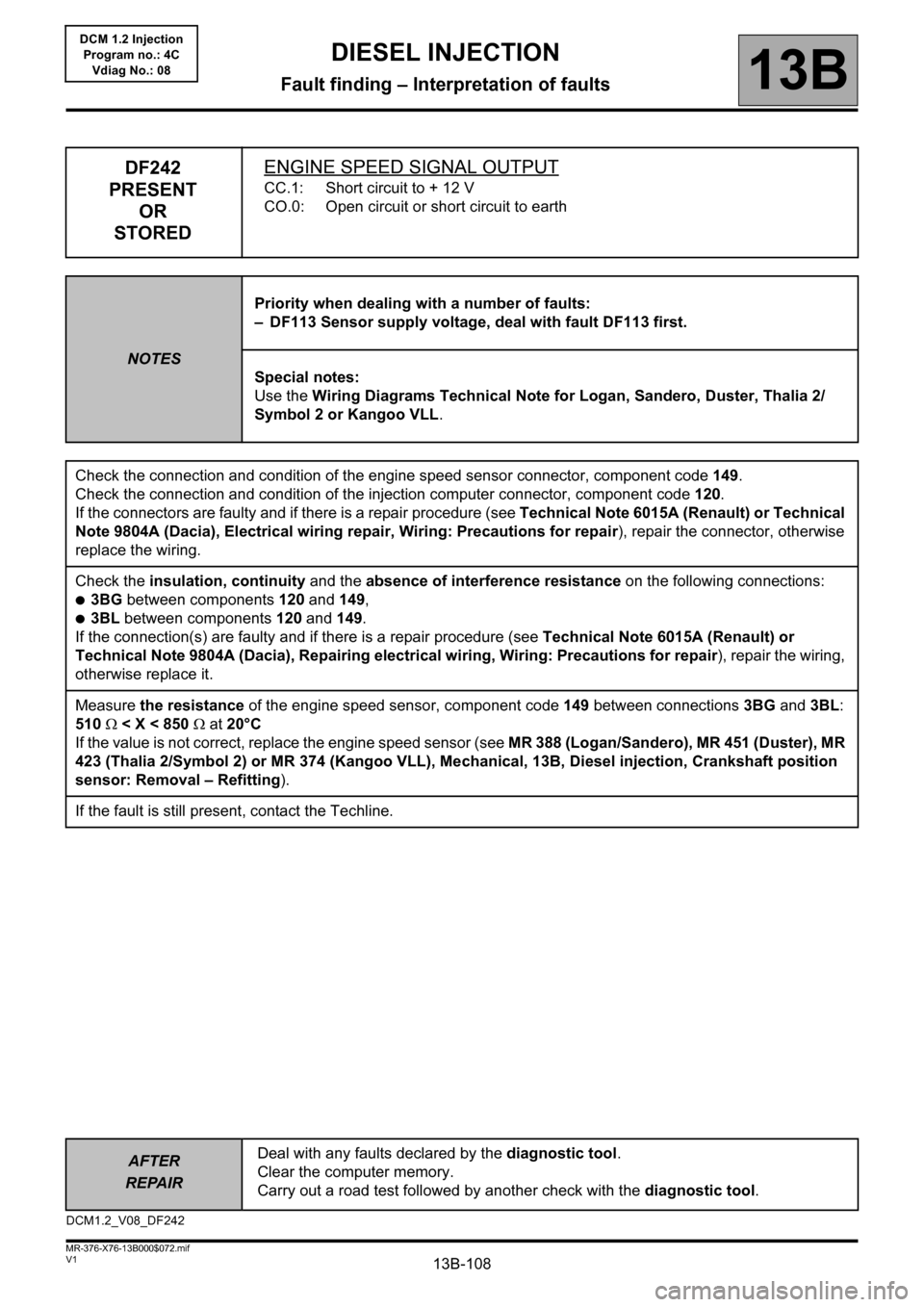
DF242
PRESENT
OR
STOREDENGINE SPEED SIGNAL OUTPUT
CC.1: Short circuit to + 12 V
CO.0: Open circuit or short circuit to earth
NOTESPriority when dealing with a number of faults:
– DF113 Sensor supply voltage, deal with fault DF113 first.
Special notes:
Use the Wiring Diagrams Technical Note for Logan, Sandero, Duster, Thalia 2/
Symbol 2 or Kangoo VLL.
Check the connection and condition of the engine speed sensor connector, component code 149.
Check the connection and condition of the injection computer connector, component code 120.
If the connectors are faulty and if there is a repair procedure (see Technical Note 6015A (Renault) or Technical
Note 9804A (Dacia), Electrical wiring repair, Wiring: Precautions for repair), repair the connector, otherwise
replace the wiring.
Check the insulation, continuity and the absence of interference resistance on the following connections:
●3BG between components 120 and 149,
●3BL between components 120 and 149.
If the connection(s) are faulty and if there is a repair procedure (see Technical Note 6015A (Renault) or
Technical Note 9804A (Dacia), Repairing electrical wiring, Wiring: Precautions for repair), repair the wiring,
otherwise replace it.
Measure the resistance of the engine speed sensor, component code 149 between connections 3BG and 3BL:
510 < X < 850 at 20°C
If the value is not correct, replace the engine speed sensor (see MR 388 (Logan/Sandero), MR 451 (Duster), MR
423 (Thalia 2/Symbol 2) or MR 374 (Kangoo VLL), Mechanical, 13B, Diesel injection, Crankshaft position
sensor: Removal – Refitting).
If the fault is still present, contact the Techline.
DCM1.2_V08_DF242