RENAULT KANGOO 2013 X61 / 2.G Engine Immobiliser Workshop Manual
Manufacturer: RENAULT, Model Year: 2013, Model line: KANGOO, Model: RENAULT KANGOO 2013 X61 / 2.GPages: 37, PDF Size: 0.22 MB
Page 1 of 37
8Electrical equipment
V1 MR-376-X76-82A000$TOC.mif
V1
82A
"The repair procedures given by the manufacturer in this document are based on the
technical specifications current when it was prepared.
The procedures may be modified as a result of changes introduced by the
manufacturer in the production of the various component units and accessories from
which his vehicles are constructed."
V1
All rights reserved by Renault s.a.s.
Edition Anglaise
Copying or translating, in part or in full, of this document or use of the service part
reference numbering system is forbidden without the prior written authority of
Renault s.a.s.
© Renault s.a.s. 2013
ENGINE IMMOBILISER
SVT
Vdiag No.: 04
Fault finding – Introduction 82A - 2
Fault finding – List and location of components 82A - 8
Fault finding – Features 82A - 9
Fault finding – Configurations and programming 82A - 10
Fault finding – Replacement of components 82A - 11
Fault finding – Fault summary table 82A - 12
Fault finding – Interpretation of faults 82A - 13
Fault finding – Conformity check 82A - 20
Fault finding – Status summary table 82A - 21
Fault finding – Interpretation of statuses 82A - 22
Fault finding – Parameter summary table 82A - 28
Fault finding – Interpretation of parameters 82A - 29
Fault finding – Customer complaints 82A - 30
Fault finding – Fault finding chart 82A - 31
Page 2 of 37
82A-2V1 MR-376-X76-82A000$010.mif
82A
SVT
Vdiag No.: 04
1. SCOPE OF THIS DOCUMENT
This document presents the fault finding method applicable to all computers with the following specifications:
2. PREREQUISITES FOR FAULT FINDING
Documentation type
Fault finding procedures (this document):
– Assisted fault finding (integrated into the diagnostic tool), Dialogys.
Wiring Diagrams:
–Visu - Schéma.
Type of diagnostic tools
– CLIP + multiplex line sensor
Special tooling required
3. SAFETY INSTRUCTIONS
Safety rules must be observed during any work on a component to prevent any material damage or personal injury:
– check the battery voltage to avoid incorrect operation of computer functions,
– use the proper tools.
– It is forbidden to carry out a road test with the diagnostic tool in dialogue with the ECU because the ABS
and Electronic Brake Distribution functions are deactivated. Braking pressure is identical on both axles of
the vehicle (risk of a spin under heavy braking).
*VLL — Very Long LifeVehicle(s): LOGAN, SANDERO, DUSTER,
MEGANE II ph1 and ph2, SCENIC II, MASTER II
ph2 and ph3, THALIA 2/SYMBOL 2, CLIO II F6,
KANGOO VLL*Computer name: SVT
Function concerned: Anti-Theft Tracking UnitVdiag No.:04
Special tooling required
Diagnostic tool
Multimeter
Elé. 1681 Universal bornier
SVT_V04_PRELI
ENGINE IMMOBILISER
Fault finding – Introduction
Page 3 of 37
82A-3V1 MR-376-X76-82A000$010.mif
ENGINE IMMOBILISER
Fault finding – Introduction82A
SVT
Vdiag No.: 04
4. REMINDER
Procedure
To run fault finding on the vehicle computers, switch on the ignition. Connect the diagnostic tool and perform the
required operations.
SCENIC II and MEGANE II:
To run fault finding on the vehicle computers, switch on the forced + after ignition feed.
Proceed as follows:
LOGAN, SANDERO, DUSTER, MASTER II ph2 and ph3, THALIA 2/SYMBOL 2, CLIO II F6, KANGOO VLL
To run fault finding on the vehicle computers, switch on the + after ignition feed.
Proceed as follows:Switch on the forced + after ignition feed:
– with the vehicle card in the card reader,
– press and hold the Start button (longer than 5 seconds) with start-up conditions not fulfilled,
– connect the diagnostic tool and perform the required operations.
Switching off the forced + after ignition feed:
Press the Start button twice briefly (less than 3 seconds).
Ensure that the + after ignition feed has been cut off by checking that the computer warning lights on the instrument
panel have gone out.
For vehicles with key/radiofrequency remote control unit,
switch on the ignition with the key.
Page 4 of 37
82A-4V1 MR-376-X76-82A000$010.mif
ENGINE IMMOBILISER
Fault finding – Introduction82A
SVT
Vdiag No.: 04
Faults
Faults are declared present or stored (depending on whether they appeared in a certain context and have
disappeared since, or whether they remain present but are not diagnosed within the current context).
The present or stored status of faults must be considered when the diagnostic tool is used after the + after ignition
feed is switched on (without operating the system components).
For a present fault, apply the procedure described in the Interpretation of faults section.
For a stored fault, note the faults displayed and apply the Notes section.
If the fault is confirmed when the instructions in the Notes section are applied, the fault is present. Deal with the
fault.
If the fault is not confirmed, check:
– the electrical lines which correspond to the fault,
– the connectors for these lines (for oxidation, bent pins, etc.),
– the resistance of the faulty component,
– the condition of the wires (melted or split insulation, wear).
Customer complaints - Fault finding chart
If the test with the diagnostic tool is OK but the customer complaint is still present, the fault should be processed by
customer complaints.
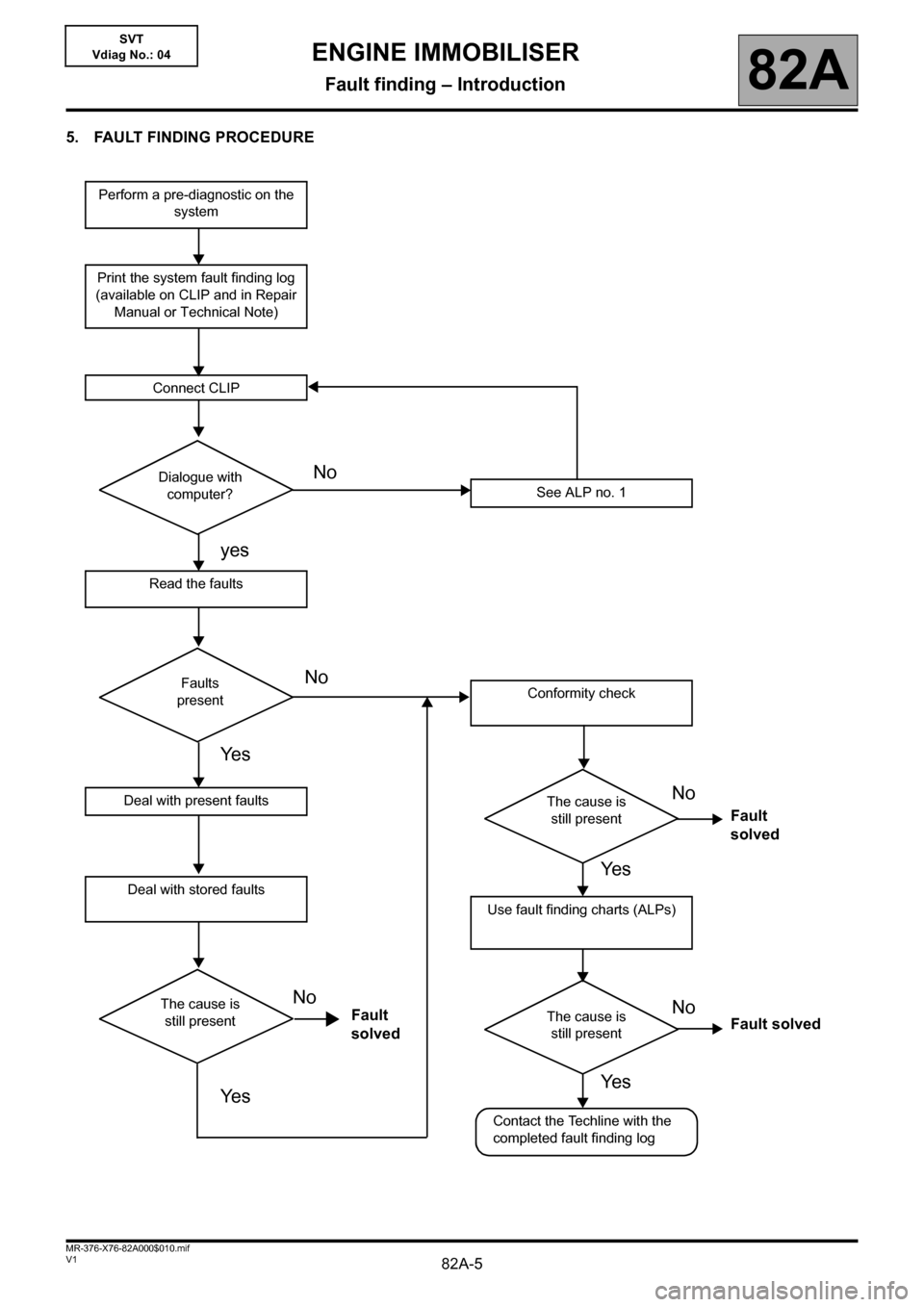
A summary of the overall procedure to follow is provided on the following page in the form of a flow chart
Page 5 of 37
82A-5V1 MR-376-X76-82A000$010.mif
ENGINE IMMOBILISER
Fault finding – Introduction82A
SVT
Vdiag No.: 04
5. FAULT FINDING PROCEDURE
Perform a pre-diagnostic on the
system
Print the system fault finding log
(available on CLIP and in Repair
Manual or Technical Note)
Connect CLIP
See ALP no. 1
Read the faults
Deal with present faults
Deal with stored faults
Conformity check
Use fault finding charts (ALPs)
Dialogue with
computer?
Faults
present
The cause is
still present
The cause is
still presentThe cause is
still present
Contact the Techline with the
completed fault finding log
No
NoNo
No No
yes
Ye s
Ye s
Fault
solvedFault solved Fault
solved
Ye s
Ye s
Page 6 of 37
82A-6V1 MR-376-X76-82A000$010.mif
ENGINE IMMOBILISER
Fault finding – Introduction82A
SVT
Vdiag No.: 04
5. FAULT FINDING PROCEDURE (continued)
Wiring check
Fault finding problems
Disconnecting the connectors and/or manipulating the wiring may temporarily remove the cause of a fault.
Electrical measurements of voltage, resistance and insulation are generally correct, especially if the fault is not
present when the analysis is made (stored fault).
Visual inspection
Look for damage under the bonnet and in the passenger compartment.
Carefully check the fuses, insulators and wiring harness routing.
Look for signs of oxidation.
Physical inspection
While manipulating the wiring, use the diagnostic tool to note any change in fault status from stored to present.
Make sure that the connectors are properly locked.
Apply light pressure to the connectors.
Twist the wiring harness.
If there is a change in status, try to locate the source of the fault.
Inspection of each component
Disconnect the connectors and check the appearance of the clips and tabs, as well as the crimping (no crimping on
the insulating section).
Make sure that the clips and tabs are properly locked in the sockets.
Check that no clips or tabs have been dislodged during connection.
Check the clip contact pressure using an appropriate model of tab.
Resistance check
Check the continuity of entire lines, then section by section.
Look for a short circuit to earth, to + 12 V or with another wire.
If a fault is detected, repair or replace the wiring harness.
Page 7 of 37
82A-7V1 MR-376-X76-82A000$010.mif
ENGINE IMMOBILISER
Fault finding – Introduction82A
SVT
Vdiag No.: 04
6. FAULT FINDING LOG
You will always be asked for this log:
• when requesting technical assistance from Techline,
• for approval requests when replacing parts for which approval is mandatory,
• to be attached to monitored parts for which reimbursement is requested. The log is needed for warranty
reimbursement, and enables better analysis of the parts removed.
7. INSTRUCTIONS TO BE FOLLOWED FOR ANY WORK CARRIED OUT ON THE INJECTION SYSTEM
Instructions to be followed before opening of the fuel circuit
Use fresh cleaning agent for each operation (used cleaning agent is contaminated). Pour it into an uncontaminated
container.
For each operation, use a clean brush in good condition (the brush must not shed its bristles).
Use a brush and cleaning agent to clean the unions to be opened.
Blast compressed air over the cleaned parts (tools, workbench, and the parts, unions and injection system area).
Check that no bristles remain.
Wash your hands before and during the operation if necessary.
When wearing leather protective gloves cover them with latex gloves to prevent contamination.
Instructions to be followed during the operation
As soon as the circuit is open, all openings must be plugged to prevent impurities from entering the system. The
plugs to be used are available from the Parts Department. The plugs must not be reused under any circumstances.
Seal the pouch shut, even if it has to be opened shortly afterwards. Ambient air carries impurities.
All components removed from the injection system must be stored in a hermetically sealed plastic bag once they
have been plugged.
The use of a brush, cleaning agent, bellows, sponge or normal cloth is strictly forbidden once the circuit has been
opened. These items could allow contamination to enter the system.
A new component replacing an old one must not be removed from its packaging until it is to be fitted to the vehicle.IMPORTANT!IMPORTANT
All faults involving a complex system call for thorough diagnostics with the appropriate tools. The
FAULT FINDING LOG, which should be completed during the fault finding procedure, ensures a
record is kept of the procedure carried out. It is an essential document when consulting the
manufacturer.
IT IS THEREFORE COMPULSORY TO COMPLETE A FAULT FINDING LOG
EACH TIME IT IS REQUESTED BY TECHLINE OR THE WARRANTY RETURNS DEPARTMENT.
Page 8 of 37
82A-8V1 MR-376-X76-82A000$020.mif
82A
SVT
Vdiag No.: 04
SVT computer:
For MEGANE II and SCENIC II:
With its attached support, it is bolted on the existing support of the dashboard cross member.
For MASTER II ph2 and ph3, THALIA 2/SYMBOL 2, CLIO II F6, KANGOO VLL:
The computer support is bolted on the existing support of the dashboard cross member.
For LOGAN, SANDERO and DUSTER:
The computer support is welded to the dashboard cross member.
The anti-theft tracking unit (computer) consists of:
– An integrated GPS aerial to locate the vehicle.
– An integrated GSM aerial to communicate with a call centre.
–A locking system that prevents the vehicle from operating when the owner of the vehicle declares to the call
centre that the vehicle has been stolen.
–An external GPS aerial can be connected to the anti-theft tracking unit, on certain vehicle types.
ENGINE IMMOBILISER
Fault finding – List and location of components
Page 9 of 37
82A-9V1 MR-376-X76-82A000$030.mif
82A
SVT
Vdiag No.: 04
For LOGAN, SANDERO, DUSTER, MASTER II ph2 and ph3, THALIA 2/SYMBOL 2, CLIO II F6, KANGOO VLL:
The computer can switch off the electrical supply of the transponder ring. When the anti-theft tracking unit receives a
locking order from the call centre via the GSM network, it switches off the supply of the transponder ring.
For MEGANE II and SCENIC II:
For "no hands-free opening" vehicles, the computer can switch off the electrical supply of the card reader. When the
anti-theft tracking unit receives a locking order from the call centre via the GSM network, it switches off the supply of
the card reader.
For "hands-free opening" vehicles, the computer can switch off the electrical supply of both the card reader and the
steering column lock. When the anti-theft tracking unit receives a locking order from the call centre via the GSM
network, it switches off the supply of these two components.
The computer has several operating modes:
–NOT FUNCTIONING mode: The computer is not supplied. No function is available, but the system retains the
stored configuration and the recorded data.
–DEACTIVATED mode: The ignition is off. The computer is supplied by the vehicle battery. Vehicle tracking by
the call centre is not activated and the GSM network does not send the vehicle position to it. The computer
stores the satellite position in its memory every 24 hours.
–FUNCTIONING WITHOUT TRACKING mode: Ignition on. The computer is supplied by the vehicle battery.
Vehicle tracking by the call centre is not activated. The computer is registered on the GSM network in case
tracking is activated. The GSM network does not send the vehicle position to the call centre. The computer
stores the satellite position in its memory every minute.
–DEACTIVATED WITH TRACKING mode: The ignition is off. The computer is supplied by the vehicle battery.
Vehicle tracking by the call centre is activated. The computer sends the vehicle position message to the call
centre every 24 hours. Each time the computer is activated, it makes a record on the GSM network and
communicates it to the call centre, but does not store it in its memory.
–FUNCTIONING WITH TRACKING mode: Ignition on. The computer is supplied by the vehicle battery. Vehicle
tracking by the call centre is activated.
The computer sends the vehicle position message to the call centre every minute. The computer stores in its
memory all operations ordered by the call centre.
–VIOLATION mode: The computer is supplied by its internal battery. The computer sends the vehicle position
message to the call centre every minute. The main supply (+ Battery) is switched off. The GPS module is
activated after a position violation is detected.
–FAULT FINDING mode: The computer is supplied by the vehicle battery or by its internal battery. The computer
communicates with the diagnostic tool.
ENGINE IMMOBILISER
Fault finding – Features
Page 10 of 37
82A-10V1 MR-376-X76-82A000$040.mif
82A
SVT
Vdiag No.: 04
SPECIAL COMMANDS
VP001 Enter VIN
This command permits manual entry of the vehicle's VIN into the computer.
Use this command each time the computer is replaced or (re)programmed.
Procedure for writing the VIN
• Establish dialogue with the computer.
• Select the menu repair mode.
• Select the other parameters menu.
• Select the line VP001.
• Enter the VIN.
• Exit fault finding mode.
• Switch off the ignition.
• Wait for the end of power latch.
• Reread the VIN in the Identification menu for confirmation (ID004 "VIN").
RZ001: Clear faults
This command is used for clearing the stored faults from the computer.
CONFIGURATION READING
CF001: CONFIGURE SVT
LC001: External GPS aerial
LC002: Timed + battery feed
LC003: Alarm
ENGINE IMMOBILISER
Fault finding – Configurations and programming