wiring RENAULT KANGOO 2013 X61 / 2.G Engine Immobiliser Workshop Manual
[x] Cancel search | Manufacturer: RENAULT, Model Year: 2013, Model line: KANGOO, Model: RENAULT KANGOO 2013 X61 / 2.GPages: 37, PDF Size: 0.22 MB
Page 2 of 37
82A-2V1 MR-376-X76-82A000$010.mif
82A
SVT
Vdiag No.: 04
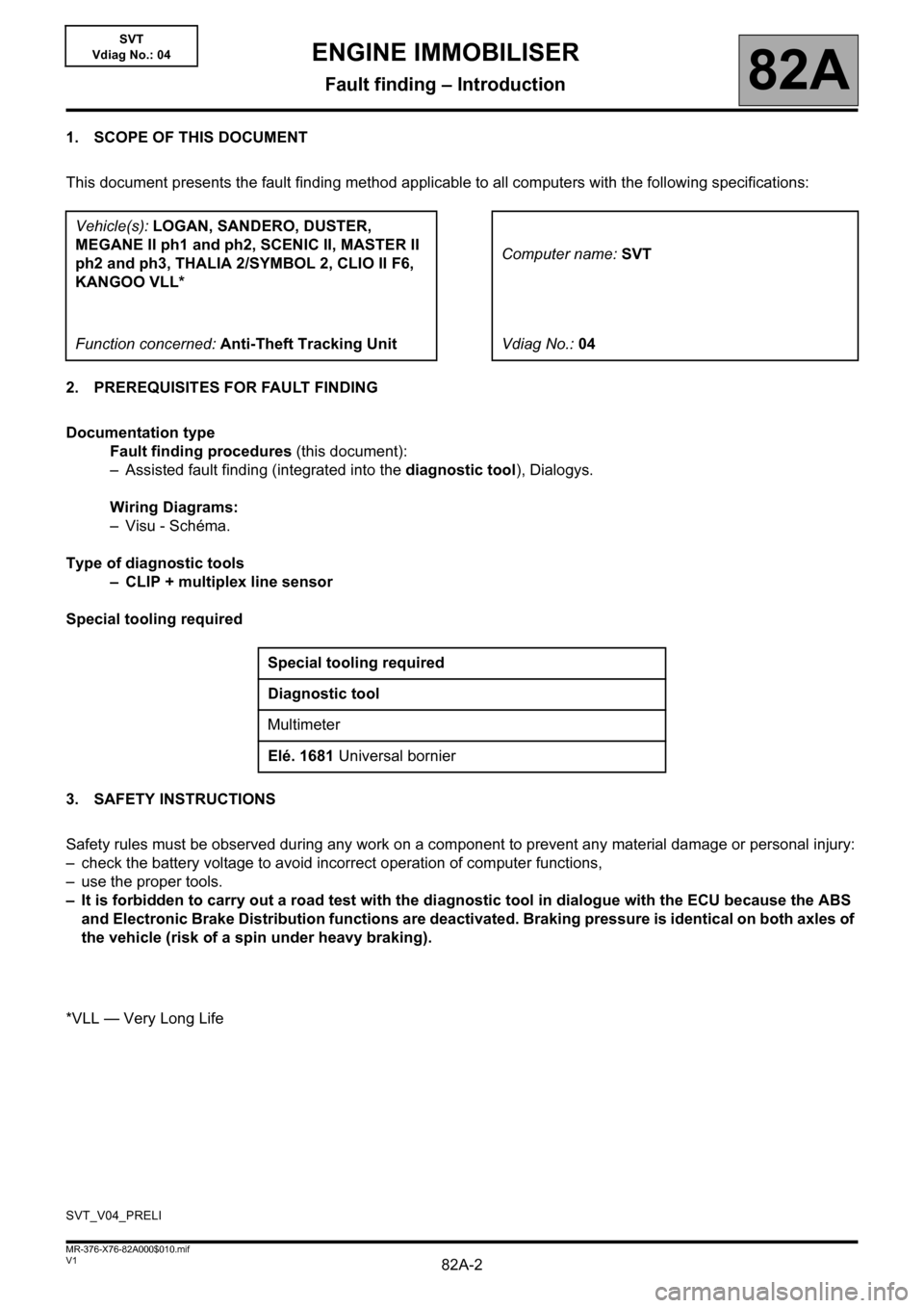
1. SCOPE OF THIS DOCUMENT
This document presents the fault finding method applicable to all computers with the following specifications:
2. PREREQUISITES FOR FAULT FINDING
Documentation type
Fault finding procedures (this document):
– Assisted fault finding (integrated into the diagnostic tool), Dialogys.
Wiring Diagrams:
–Visu - Schéma.
Type of diagnostic tools
– CLIP + multiplex line sensor
Special tooling required
3. SAFETY INSTRUCTIONS
Safety rules must be observed during any work on a component to prevent any material damage or personal injury:
– check the battery voltage to avoid incorrect operation of computer functions,
– use the proper tools.
– It is forbidden to carry out a road test with the diagnostic tool in dialogue with the ECU because the ABS
and Electronic Brake Distribution functions are deactivated. Braking pressure is identical on both axles of
the vehicle (risk of a spin under heavy braking).
*VLL — Very Long LifeVehicle(s): LOGAN, SANDERO, DUSTER,
MEGANE II ph1 and ph2, SCENIC II, MASTER II
ph2 and ph3, THALIA 2/SYMBOL 2, CLIO II F6,
KANGOO VLL*Computer name: SVT
Function concerned: Anti-Theft Tracking UnitVdiag No.:04
Special tooling required
Diagnostic tool
Multimeter
Elé. 1681 Universal bornier
SVT_V04_PRELI
ENGINE IMMOBILISER
Fault finding – Introduction
Page 6 of 37
82A-6V1 MR-376-X76-82A000$010.mif
ENGINE IMMOBILISER
Fault finding – Introduction82A
SVT
Vdiag No.: 04
5. FAULT FINDING PROCEDURE (continued)
Wiring check
Fault finding problems
Disconnecting the connectors and/or manipulating the wiring may temporarily remove the cause of a fault.
Electrical measurements of voltage, resistance and insulation are generally correct, especially if the fault is not
present when the analysis is made (stored fault).
Visual inspection
Look for damage under the bonnet and in the passenger compartment.
Carefully check the fuses, insulators and wiring harness routing.
Look for signs of oxidation.
Physical inspection
While manipulating the wiring, use the diagnostic tool to note any change in fault status from stored to present.
Make sure that the connectors are properly locked.
Apply light pressure to the connectors.
Twist the wiring harness.
If there is a change in status, try to locate the source of the fault.
Inspection of each component
Disconnect the connectors and check the appearance of the clips and tabs, as well as the crimping (no crimping on
the insulating section).
Make sure that the clips and tabs are properly locked in the sockets.
Check that no clips or tabs have been dislodged during connection.
Check the clip contact pressure using an appropriate model of tab.
Resistance check
Check the continuity of entire lines, then section by section.
Look for a short circuit to earth, to + 12 V or with another wire.
If a fault is detected, repair or replace the wiring harness.
Page 31 of 37
82A-31
AFTER REPAIRDeal with any faults displayed by the diagnostic tool.
Clear the faults from the computer memory using command RZ001 Fault memory.
V1 MR-376-X76-82A000$110.mif
82A
SVT
Vdiag No.: 04
ALP1 NO DIALOGUE WITH THE COMPUTER
NOTESSwitch on the vehicle + after ignition feed.
Use the Wiring Diagrams Technical Note for LOGAN, SANDERO, DUSTER,
MEGANE II ph1 and ph2, SCENIC II, MASTER II ph2 and ph3, THALIA 2/SYMBOL
2, CLIO II F6, KANGOO VLL.
Ensure that the diagnostic tool is not the cause of the fault by using it to establish dialogue with a
computer on another vehicle. If the diagnostic tool is not causing the fault and dialogue cannot be established
with any other computer on the same vehicle, it may be that a faulty computer is disrupting the fault finding line.
Use a process of successive disconnections to locate this computer.
Check the battery voltage, component code 107, and perform the necessary operations to obtain the correct
voltage (12 V < X < 15 V).
Check the condition of the fuses in the passenger compartment fuse and relay box, component code 260 for
MEGANE II ph1 and ph2, SCENIC II, KANGOO VLL or component code 1016 for LOGAN, SANDERO, DUSTER,
MASTER II ph2 and ph3, THALIA 2/SYMBOL 2, CLIO II F6.
Check the connection of the anti-theft tracking unit connector, component code 2186.
If the connector is faulty and if there is a repair procedure (see Technical Note 6015A, Electrical wiring repair,
Wiring: Precautions for repair), repair the connector, otherwise replace the wiring.
SVT_V04_ALP001
ENGINE IMMOBILISER
Fault finding – Fault finding chart
Page 32 of 37
82A-32
AFTER REPAIRDeal with any faults displayed by the diagnostic tool.
Clear the faults from the computer memory using command RZ001 Fault memory.
V1 MR-376-X76-82A000$110.mif
ENGINE IMMOBILISER
Fault finding – Fault finding chart82A
SVT
Vdiag No.: 04
ALP1
CONTINUED 1
For MEGANE II and SCENIC II, check the connection of the Protection and Switching Unit connector, component
code 1337.
If the connector is faulty and if there is a repair procedure (see Technical Note 6015A, Electrical wiring repair,
Wiring: Precautions for repair), repair the connector, otherwise replace the wiring.
For CLIO II F6, check the connection of the UCH connector, component code 645.
If the connector is faulty and if there is a repair method (see Technical Note 6015A, Electrical
wiring repair: Precautions for repair), repair the connector, otherwise replace the wiring.
Check the continuity, insulation and the absence of interference resistance on the following connections:
For LOGAN, SANDERO, DUSTER, THALIA 2/SYMBOL 2, CLIO II F6:
–BP56 between components 2186 and 1016 (+ before ignition feed),
–AP10 between components 2186 and 1016 (+ after ignition feed),
–NC of component 2186 (for SANDERO and LOGAN).
–N of component 2186 (for THALIA 2/SYMBOL 2 and CLIO II F6)
–BP56 between components 2186 and 645 (for Clio II F6)
For MEGANE II and SCENIC II:
–BP32 between components 2186 and 260 (+ before ignition feed),
–AP43 between components 2186 and 1337 (+ after ignition feed),
–MAN of component 2186.
Page 33 of 37

82A-33
AFTER REPAIRDeal with any faults displayed by the diagnostic tool.
Clear the faults from the computer memory using command RZ001 Fault memory.
V1 MR-376-X76-82A000$110.mif
ENGINE IMMOBILISER
Fault finding – Fault finding chart82A
SVT
Vdiag No.: 04
ALP1
CONTINUED 2
For MASTER II:
–BP between components 2186 and 1016 (+ before ignition feed),
–AP between components 2186 and 1016 (+ after ignition feed),
–Earth of component 2186.
For KANGOO VLL:
–BP3 and BP10 between components 2186 and 260 (+ before ignition feed),
–AP10 between components 2186 and 260 (+ after ignition feed),
–NA of component 2186.
If the connection or connections are faulty and there is a repair method (see Technical Note 6015A, Electrical
wiring repair, Wiring: Precautions for repair), repair the wiring, otherwise replace the wiring.
Page 34 of 37
82A-34
AFTER REPAIRDeal with any faults displayed by the diagnostic tool.
Clear the faults from the computer memory using command RZ001 Fault memory.
V1 MR-376-X76-82A000$110.mif
ENGINE IMMOBILISER
Fault finding – Fault finding chart82A
SVT
Vdiag No.: 04
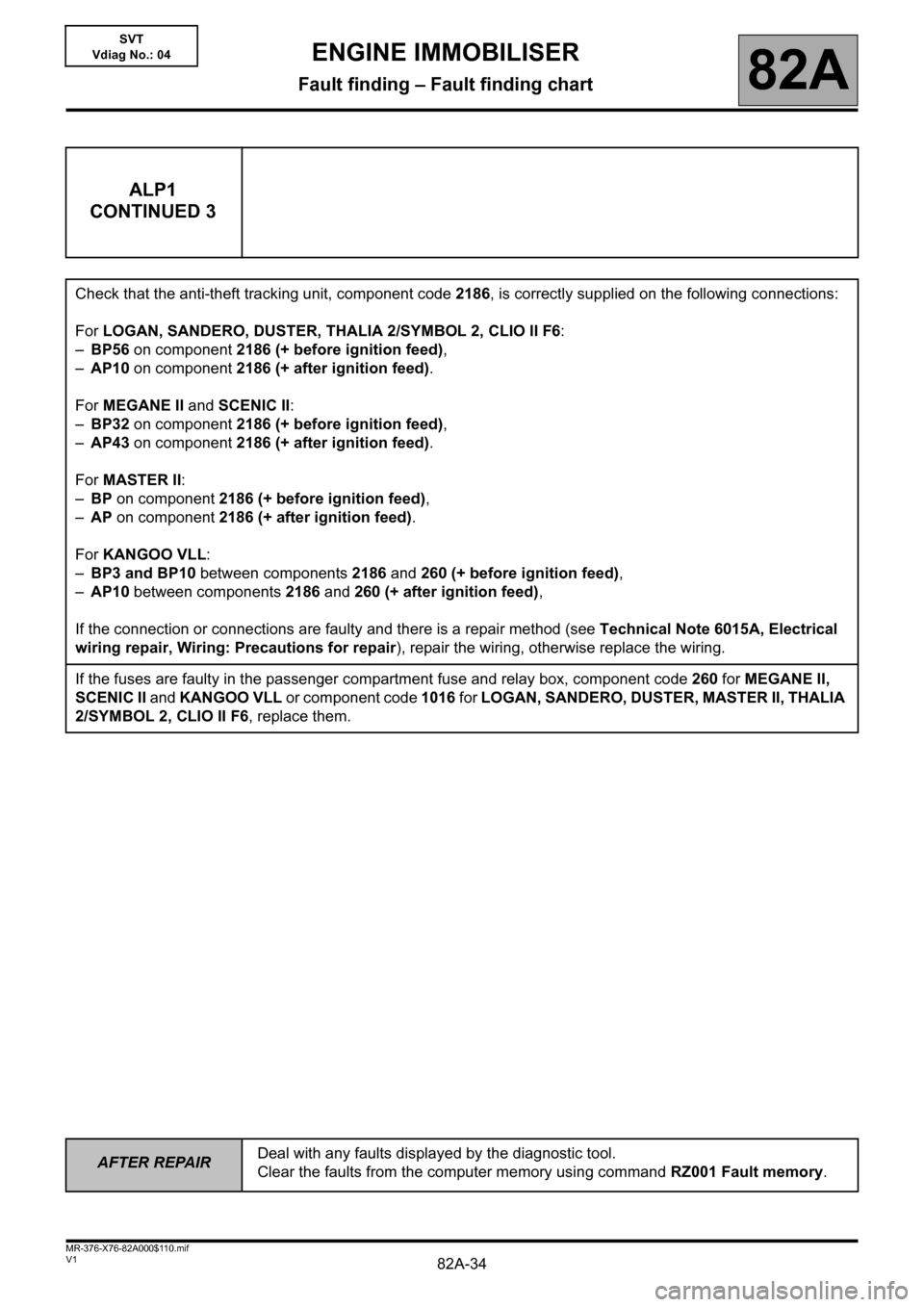
ALP1
CONTINUED 3
Check that the anti-theft tracking unit, component code 2186, is correctly supplied on the following connections:
For LOGAN, SANDERO, DUSTER, THALIA 2/SYMBOL 2, CLIO II F6:
–BP56 on component 2186 (+ before ignition feed),
–AP10 on component 2186 (+ after ignition feed).
For MEGANE II and SCENIC II:
–BP32 on component 2186 (+ before ignition feed),
–AP43 on component 2186 (+ after ignition feed).
For MASTER II:
–BP on component 2186 (+ before ignition feed),
–AP on component 2186 (+ after ignition feed).
For KANGOO VLL:
–BP3 and BP10 between components 2186 and 260 (+ before ignition feed),
–AP10 between components 2186 and 260 (+ after ignition feed),
If the connection or connections are faulty and there is a repair method (see Technical Note 6015A, Electrical
wiring repair, Wiring: Precautions for repair), repair the wiring, otherwise replace the wiring.
If the fuses are faulty in the passenger compartment fuse and relay box, component code 260 for MEGANE II,
SCENIC II and KANGOO VLL or component code 1016 for LOGAN, SANDERO, DUSTER, MASTER II, THALIA
2/SYMBOL 2, CLIO II F6, replace them.
Page 35 of 37
82A-35
AFTER REPAIRDeal with any faults displayed by the diagnostic tool.
Clear the faults from the computer memory using command RZ001 Fault memory.
V1 MR-376-X76-82A000$110.mif
ENGINE IMMOBILISER
Fault finding – Fault finding chart82A
SVT
Vdiag No.: 04
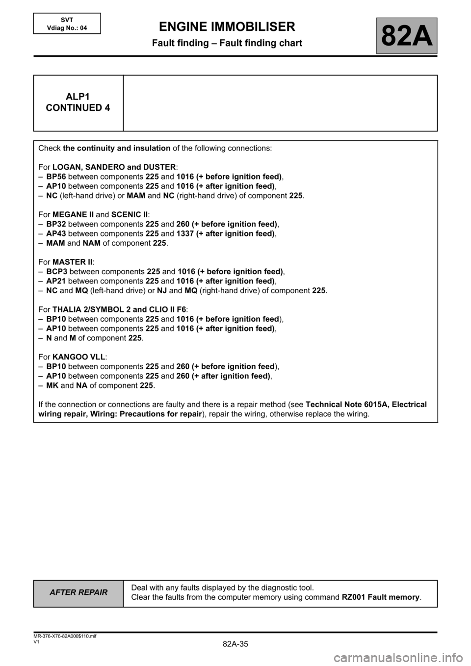
ALP1
CONTINUED 4
Check the continuity and insulation of the following connections:
For LOGAN, SANDERO and DUSTER:
–BP56 between components 225 and 1016 (+ before ignition feed),
–AP10 between components 225 and 1016 (+ after ignition feed),
–NC (left-hand drive) or MAM and NC (right-hand drive) of component 225.
For MEGANE II and SCENIC II:
–BP32 between components 225 and 260 (+ before ignition feed),
–AP43 between components 225 and 1337 (+ after ignition feed),
–MAM and NAM of component 225.
For MASTER II:
–BCP3 between components 225 and 1016 (+ before ignition feed),
–AP21 between components 225 and 1016 (+ after ignition feed),
–NC and MQ (left-hand drive) or NJ and MQ (right-hand drive) of component 225.
For THALIA 2/SYMBOL 2 and CLIO II F6:
–BP10 between components 225 and 1016 (+ before ignition feed),
–AP10 between components 225 and 1016 (+ after ignition feed)
,
–N and M of component 225.
For KANGOO VLL:
–BP10 between components 225 and 260 (+ before ignition feed),
–AP10 between components 225 and 260 (+ after ignition feed),
–MK and NA of component 225.
If the connection or connections are faulty and there is a repair method (see Technical Note 6015A, Electrical
wiring repair, Wiring: Precautions for repair), repair the wiring, otherwise replace the wiring.
Page 36 of 37
82A-36
AFTER REPAIRDeal with any faults displayed by the diagnostic tool.
Clear the faults from the computer memory using command RZ001 Fault memory.
V1 MR-376-X76-82A000$110.mif
ENGINE IMMOBILISER
Fault finding – Fault finding chart82A
SVT
Vdiag No.: 04
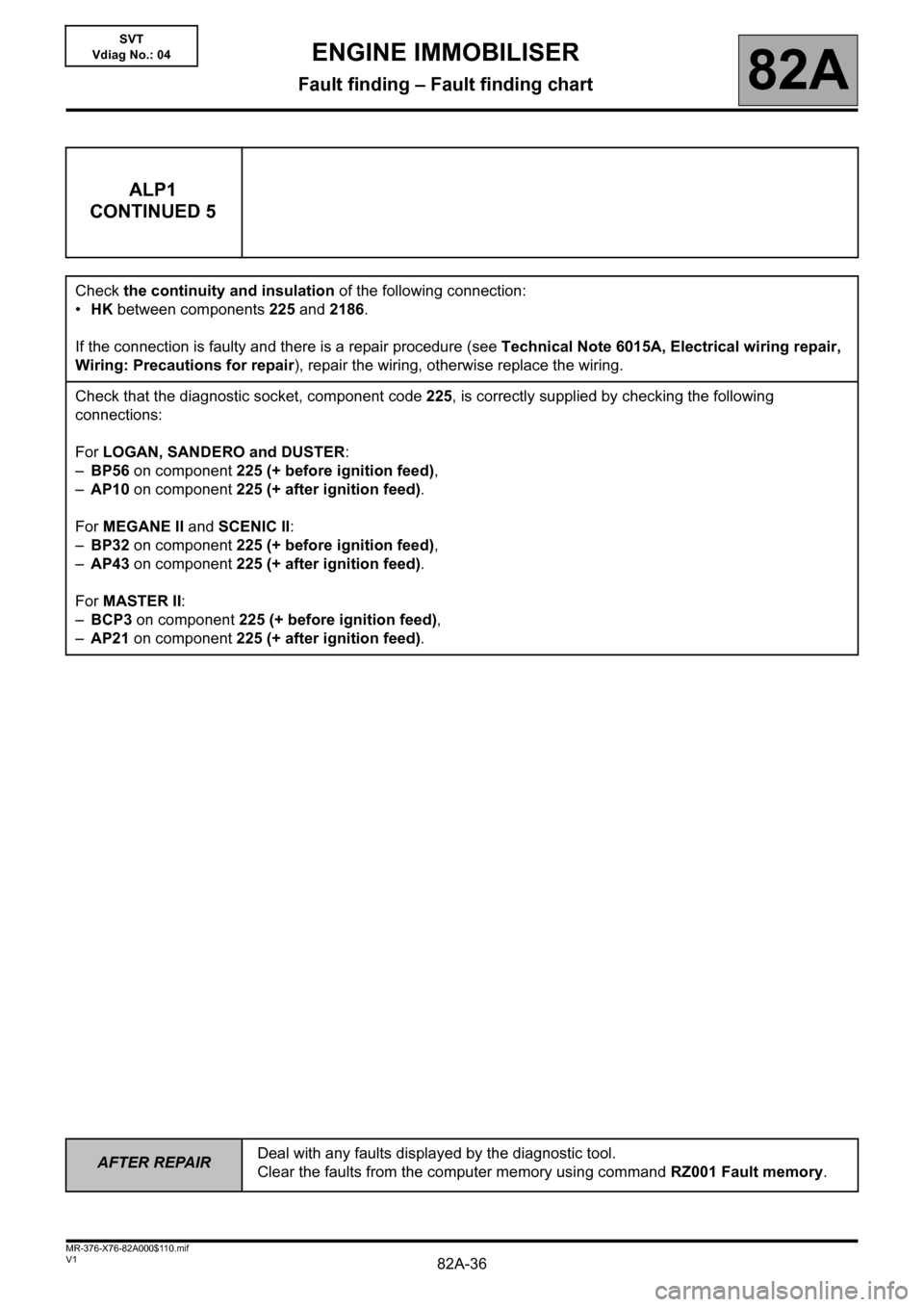
ALP1
CONTINUED 5
Check the continuity and insulation of the following connection:
•HK between components 225 and 2186.
If the connection is faulty and there is a repair procedure (see Technical Note 6015A, Electrical wiring repair,
Wiring: Precautions for repair), repair the wiring, otherwise replace the wiring.
Check that the diagnostic socket, component code 225, is correctly supplied by checking the following
connections:
For LOGAN, SANDERO and DUSTER:
–BP56 on component 225 (+ before ignition feed),
–AP10 on component 225 (+ after ignition feed).
For MEGANE II and SCENIC II:
–BP32 on component 225 (+ before ignition feed),
–AP43 on component 225 (+ after ignition feed).
For MASTER II:
–BCP3 on component 225 (+ before ignition feed),
–AP21 on component 225 (+ after ignition feed).
Page 37 of 37
82A-37
AFTER REPAIRDeal with any faults displayed by the diagnostic tool.
Clear the faults from the computer memory using command RZ001 Fault memory.
V1 MR-376-X76-82A000$110.mif
ENGINE IMMOBILISER
Fault finding – Fault finding chart82A
SVT
Vdiag No.: 04
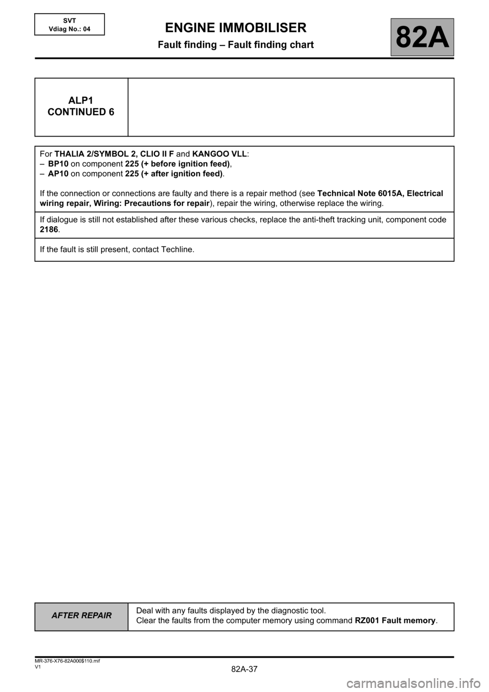
ALP1
CONTINUED 6
For THALIA 2/SYMBOL 2, CLIO II F and KANGOO VLL:
–BP10 on component 225 (+ before ignition feed),
–AP10 on component 225 (+ after ignition feed).
If the connection or connections are faulty and there is a repair method (see Technical Note 6015A, Electrical
wiring repair, Wiring: Precautions for repair), repair the wiring, otherwise replace the wiring.
If dialogue is still not established after these various checks, replace the anti-theft tracking unit, component code
2186.
If the fault is still present, contact Techline.