brake sensor RENAULT KANGOO 2013 X61 / 2.G Petrol V42 Injection Owner's Manual
[x] Cancel search | Manufacturer: RENAULT, Model Year: 2013, Model line: KANGOO, Model: RENAULT KANGOO 2013 X61 / 2.GPages: 279, PDF Size: 1.29 MB
Page 140 of 279
17B-140
AFTER REPAIRDeal with any faults displayed by the diagnostic tool.
Clear the computer fault memory.
Carry out a road test followed by another check with the diagnostic tool.
V2 MR-376-X76-17B050$084.mif
PETROL INJECTION
Fault finding – Interpretation of faults17B
V42 Injection
Program No.: 2A
Vdiag No.: 04, 05, 06,
14, 16, 18
DF1034
CONTINUED
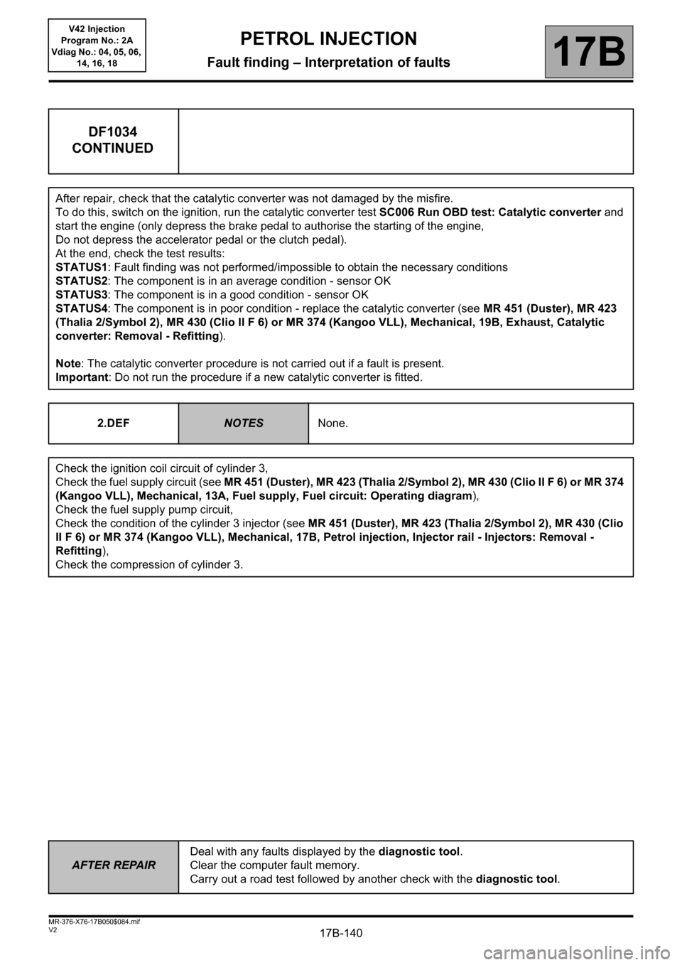
After repair, check that the catalytic converter was not damaged by the misfire.
To do this, switch on the ignition, run the catalytic converter test SC006 Run OBD test: Catalytic converter and
start the engine (only depress the brake pedal to authorise the starting of the engine,
Do not depress the accelerator pedal or the clutch pedal).
At the end, check the test results:
STATUS1: Fault finding was not performed/impossible to obtain the necessary conditions
STATUS2: The component is in an average condition - sensor OK
STATUS3: The component is in a good condition - sensor OK
STATUS4: The component is in poor condition - replace the catalytic converter (see MR 451 (Duster), MR 423
(Thalia 2/Symbol 2), MR 430 (Clio II F 6) or MR 374 (Kangoo VLL), Mechanical, 19B, Exhaust, Catalytic
converter: Removal - Refitting).
Note: The catalytic converter procedure is not carried out if a fault is present.
Important: Do not run the procedure if a new catalytic converter is fitted.
2.DEF
NOTESNone.
Check the ignition coil circuit of cylinder 3,
Check the fuel supply circuit (see MR 451 (Duster), MR 423 (Thalia 2/Symbol 2), MR 430 (Clio II F 6) or MR 374
(Kangoo VLL), Mechanical, 13A, Fuel supply, Fuel circuit: Operating diagram),
Check the fuel supply pump circuit,
Check the condition of the cylinder 3 injector (see MR 451 (Duster), MR 423 (Thalia 2/Symbol 2), MR 430 (Clio
II F 6) or MR 374 (Kangoo VLL), Mechanical, 17B, Petrol injection, Injector rail - Injectors: Removal -
Refitting),
Check the compression of cylinder 3.
Page 176 of 279
17B-176V2 MR-376-X76-17B050$110.mif
PETROL INJECTION
Fault finding – Interpretation of statuses17B
V42 Injection
Program No.: 2A
Vdiag No.: 04, 05, 06,
14, 16, 18
AFTER REPAIRDeal with any faults. Clear the faults from the computer memory.
Switch off the ignition and carry out a road test followed by a test with the diagnostic
tool.
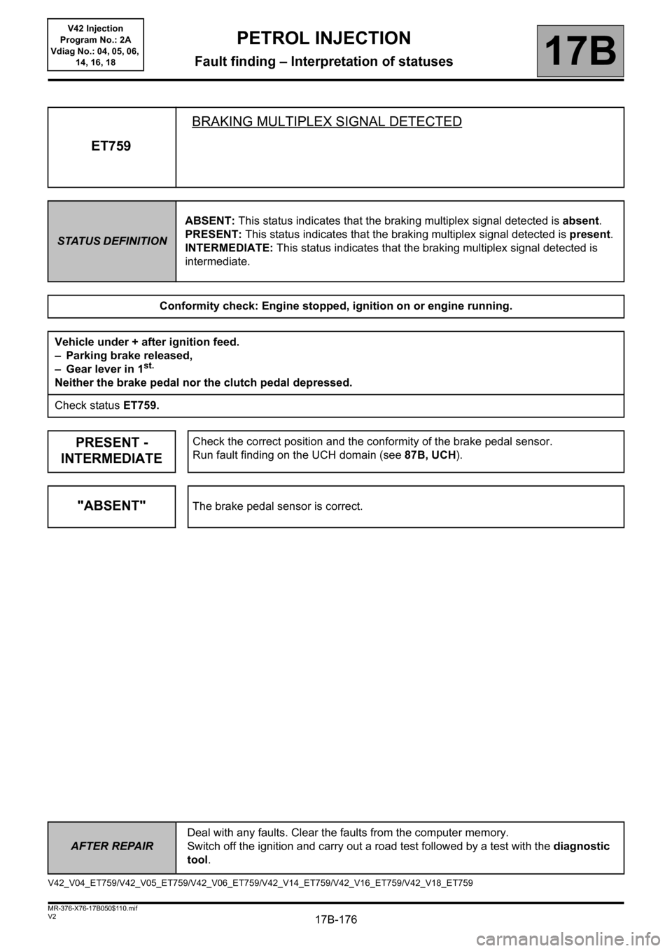
ET759BRAKING MULTIPLEX SIGNAL DETECTED
STATUS DEFINITIONABSENT: This status indicates that the braking multiplex signal detected is absent.
PRESENT: This status indicates that the braking multiplex signal detected is present.
INTERMEDIATE: This status indicates that the braking multiplex signal detected is
intermediate.
Conformity check: Engine stopped, ignition on or engine running.
Vehicle under + after ignition feed.
– Parking brake released,
– Gear lever in 1
st.
Neither the brake pedal nor the clutch pedal depressed.
Check status ET759.
PRESENT -
INTERMEDIATECheck the correct position and the conformity of the brake pedal sensor.
Run fault finding on the UCH domain (see 87B, UCH).
"ABSENT"The brake pedal sensor is correct.
V42_V04_ET759/V42_V05_ET759/V42_V06_ET759/V42_V14_ET759/V42_V16_ET759/V42_V18_ET759
Page 182 of 279
17B-182V2 MR-376-X76-17B050$120.mif
PETROL INJECTION
Fault finding – Parameter summary table17B
V42 Injection
Program No.: 2A
Vdiag No.: 04, 05, 06,
14, 16, 18
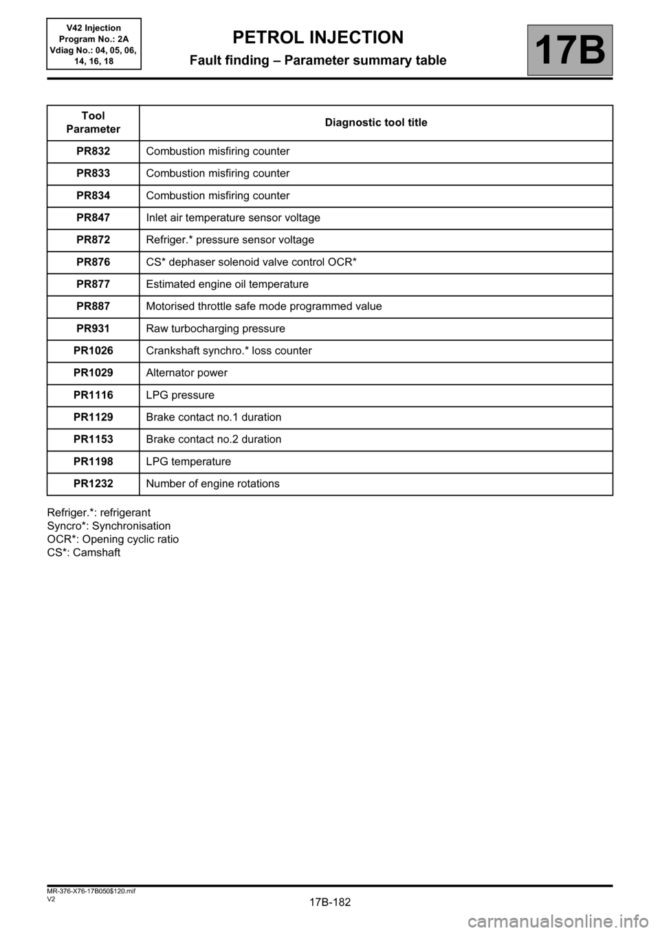
Refriger.*: refrigerant
Syncro*: Synchronisation
OCR*: Opening cyclic ratio
CS*: CamshaftTool
ParameterDiagnostic tool title
PR832Combustion misfiring counter
PR833Combustion misfiring counter
PR834Combustion misfiring counter
PR847Inlet air temperature sensor voltage
PR872Refriger.* pressure sensor voltage
PR876CS* dephaser solenoid valve control OCR*
PR877Estimated engine oil temperature
PR887Motorised throttle safe mode programmed value
PR931Raw turbocharging pressure
PR1026Crankshaft synchro.* loss counter
PR1029 Alternator power
PR1116LPG pressure
PR1129 Brake contact no.1 duration
PR1153 Brake contact no.2 duration
PR1198LPG temperature
PR1232Number of engine rotations
Page 240 of 279
17B-240
AFTER REPAIRCarry out a road test, then check with the diagnostic tool.
V2 MR-376-X76-17B050$160.mif
PETROL INJECTION
Fault finding – Fault Finding Chart17B
V42 Injection
Program No.: 2A
Vdiag No.: 04, 05, 06,
14, 16, 18
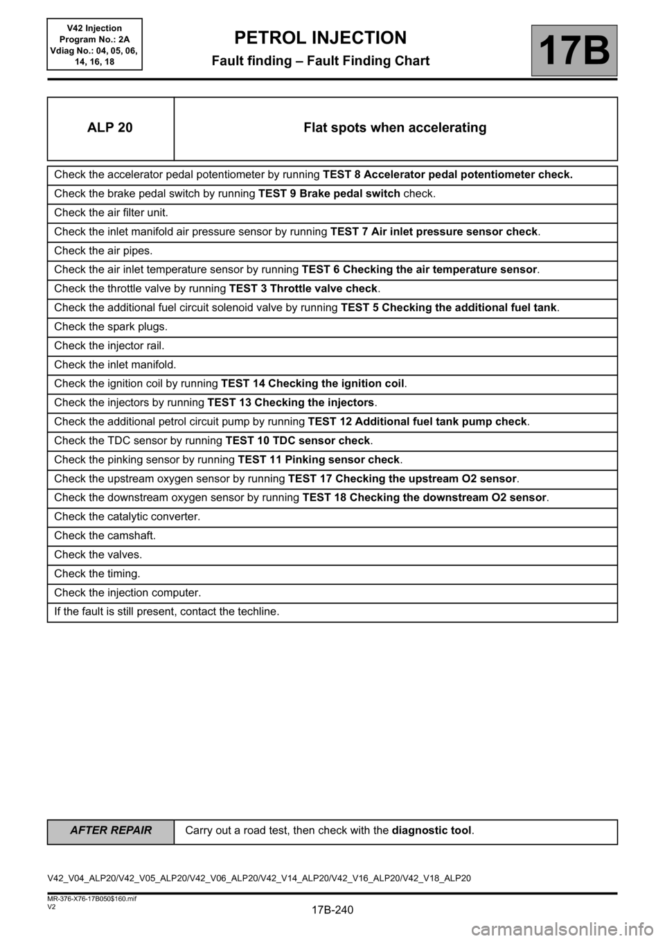
ALP 20 Flat spots when accelerating
Check the accelerator pedal potentiometer by running TEST 8 Accelerator pedal potentiometer check.
Check the brake pedal switch by running TEST 9 Brake pedal switch check.
Check the air filter unit.
Check the inlet manifold air pressure sensor by running TEST 7 Air inlet pressure sensor check.
Check the air pipes.
Check the air inlet temperature sensor by running TEST 6 Checking the air temperature sensor.
Check the throttle valve by running TEST 3 Throttle valve check.
Check the additional fuel circuit solenoid valve by running TEST 5 Checking the additional fuel tank.
Check the spark plugs.
Check the injector rail.
Check the inlet manifold.
Check the ignition coil by running TEST 14 Checking the ignition coil.
Check the injectors by running TEST 13 Checking the injectors.
Check the additional petrol circuit pump by running TEST 12 Additional fuel tank pump check.
Check the TDC sensor by running TEST 10 TDC sensor check.
Check the pinking sensor by running TEST 11 Pinking sensor check.
Check the upstream oxygen sensor by running TEST 17 Checking the upstream O2 sensor.
Check the downstream oxygen sensor by running TEST 18 Checking the downstream O2 sensor.
Check the catalytic converter.
Check the camshaft.
Check the valves.
Check the timing.
Check the injection computer.
If the fault is still present, contact the techline.
V42_V04_ALP20/V42_V05_ALP20/V42_V06_ALP20/V42_V14_ALP20/V42_V16_ALP20/V42_V18_ALP20
Page 243 of 279
17B-243
AFTER REPAIRCarry out a road test, then check with the diagnostic tool.
V2 MR-376-X76-17B050$160.mif
PETROL INJECTION
Fault finding – Fault Finding Chart17B
V42 Injection
Program No.: 2A
Vdiag No.: 04, 05, 06,
14, 16, 18
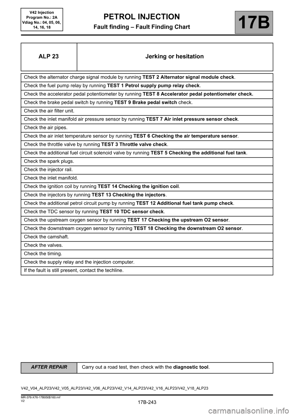
ALP 23 Jerking or hesitation
Check the alternator charge signal module by running TEST 2 Alternator signal module check.
Check the fuel pump relay by running TEST 1 Petrol supply pump relay check.
Check the accelerator pedal potentiometer by running TEST 8 Accelerator pedal potentiometer check.
Check the brake pedal switch by running TEST 9 Brake pedal switch check.
Check the air filter unit.
Check the inlet manifold air pressure sensor by running TEST 7 Air inlet pressure sensor check.
Check the air pipes.
Check the air inlet temperature sensor by running TEST 6 Checking the air temperature sensor.
Check the throttle valve by running TEST 3 Throttle valve check.
Check the additional fuel circuit solenoid valve by running TEST 5 Checking the additional fuel tank.
Check the spark plugs.
Check the injector rail.
Check the inlet manifold.
Check the ignition coil by running TEST 14 Checking the ignition coil.
Check the injectors by running TEST 13 Checking the injectors.
Check the additional petrol circuit pump by running TEST 12 Additional fuel tank pump check.
Check the TDC sensor by running TEST 10 TDC sensor check.
Check the upstream oxygen sensor by running TEST 17 Checking the upstream O2 sensor.
Check the downstream oxygen sensor by running TEST 18 Checking the downstream O2 sensor.
Check the camshaft.
Check the valves.
Check the timing.
Check the supply relay and the injection computer.
If the fault is still present, contact the techline.
V42_V04_ALP23/V42_V05_ALP23/V42_V06_ALP23/V42_V14_ALP23/V42_V16_ALP23/V42_V18_ALP23
Page 248 of 279
17B-248V2 MR-376-X76-17B050$170.mif
17B
V42 Injection
Program No.: 2A
Vdiag No.: 04, 05, 06,
14, 16, 18
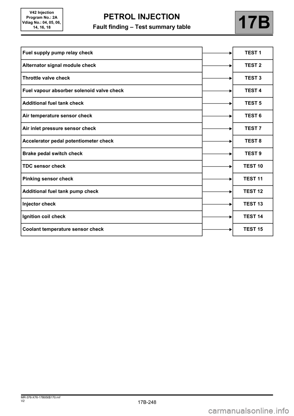
Fuel supply pump relay check TEST 1
Alternator signal module check TEST 2
Throttle valve checkTEST 3
Fuel vapour absorber solenoid valve check TEST 4
Additional fuel tank checkTEST 5
Air temperature sensor check TEST 6
Air inlet pressure sensor check TEST 7
Accelerator pedal potentiometer check TEST 8
Brake pedal switch checkTEST 9
TDC sensor checkTEST 10
Pinking sensor checkTEST 11
Additional fuel tank pump check TEST 12
Injector checkTEST 13
Ignition coil checkTEST 14
Coolant temperature sensor check TEST 15
PETROL INJECTION
Fault finding – Test summary table
Page 275 of 279
17B-275
AFTER REPAIRCarry out a road test, then check with the diagnostic tool.
V2 MR-376-X76-17B050$180.mif
PETROL INJECTION
Fault finding – Tests17B
V42 Injection
Program No.: 2A
Vdiag No.: 04, 05, 06,
14, 16, 18
TDC*: TOP DEAD CENTRE
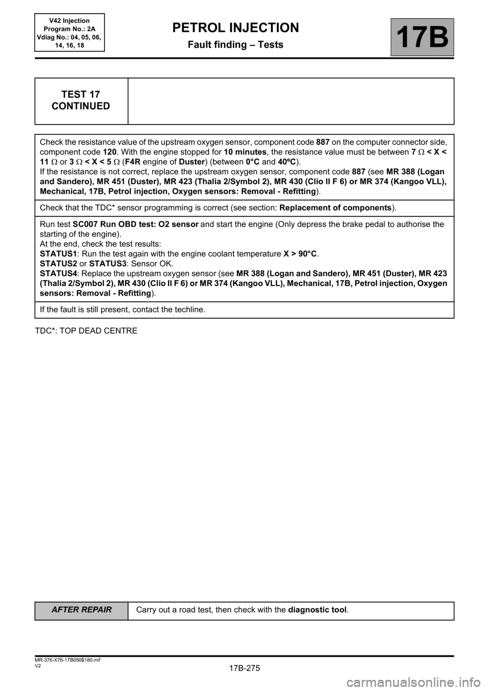
TEST 17
CONTINUED
Check the resistance value of the upstream oxygen sensor, component code 887 on the computer connector side,
component code 120. With the engine stopped for 10 minutes, the resistance value must be between 7< X <
11 or 3 < X < 5 (F4R engine of Duster) (between 0°C and 40ºC).
If the resistance is not correct, replace the upstream oxygen sensor, component code 887 (see MR 388 (Logan
and Sandero), MR 451 (Duster), MR 423 (Thalia 2/Symbol 2), MR 430 (Clio II F 6) or MR 374 (Kangoo VLL),
Mechanical, 17B, Petrol injection, Oxygen sensors: Removal - Refitting).
Check that the TDC* sensor programming is correct (see section: Replacement of components).
Run test SC007 Run OBD test: O2 sensor
and start the engine (Only depress the brake pedal to authorise the
starting of the engine).
At the end, check the test results:
STATUS1: Run the test again with the engine coolant temperature X > 90°C.
STATUS2 or STATUS3: Sensor OK.
STATUS4: Replace the upstream oxygen sensor (see MR 388 (Logan and Sandero), MR 451 (Duster), MR 423
(Thalia 2/Symbol 2), MR 430 (Clio II F 6) or MR 374 (Kangoo VLL), Mechanical, 17B, Petrol injection, Oxygen
sensors: Removal - Refitting).
If the fault is still present, contact the techline.