Diagram RENAULT KANGOO 2013 X61 / 2.G Petrol V42 Injection Workshop Manual
[x] Cancel search | Manufacturer: RENAULT, Model Year: 2013, Model line: KANGOO, Model: RENAULT KANGOO 2013 X61 / 2.GPages: 279, PDF Size: 1.29 MB
Page 1 of 279
1Engine and peripherals
V2 MR-376-X76-17B050$TOC.mif
V2
17B
"The repair procedures given by the manufacturer in this document are based on the
technical specifications current when it was prepared.
The procedures may be modified as a result of changes introduced by the
manufacturer in the production of the various component units and accessories from
which his vehicles are constructed."
V2
All rights reserved by Renault s.a.s.
Edition Anglaise
Copying or translating, in part or in full, of this document or use of the service part
reference numbering system is forbidden without the prior written authority of
Renault s.a.s.
© Renault s.a.s. 2014
PETROL INJECTION
V42 Injection
Program No.: 2A
Vdiag No.: 04, 05, 06, 14, 16, 18
Fault finding – Introduction 17B - 2
Fault finding – List and location of components 17B - 4
Fault finding – Role of components 17B - 5
Fault finding – Operating diagram 17B - 7
Fault finding – Features 17B - 9
Fault finding – Replacement of components 17B - 12
Fault finding – Fault summary table 17B - 16
Fault finding – Interpretation of faults 17B - 21
Fault finding – Conformity check 17B - 160
Fault finding – Status summary table 17B - 161
Fault finding – Interpretation of statuses 17B - 163
Fault finding – Parameter summary table 17B - 180
Fault finding – Interpretation of parameters 17B - 183
Fault finding – Command summary table 17B - 213
Fault finding – Customer complaints 17B - 215
Fault finding – Fault Finding Chart 17B - 220
Fault finding – Test summary table 17B - 248
Fault finding – Tests 17B - 250
Page 2 of 279
17B-2V2 MR-376-X76-17B050$010.mif
17B
V42 Injection
Program No.: 2A
Vdiag No.: 04, 05, 06,
14, 16, 18
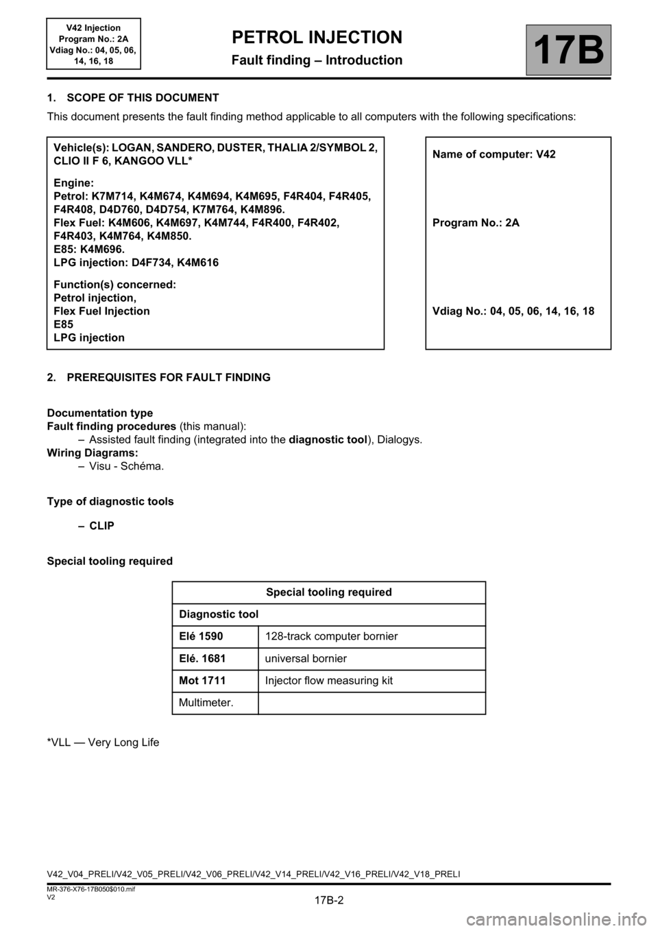
1. SCOPE OF THIS DOCUMENT
This document presents the fault finding method applicable to all computers with the following specifications:
2. PREREQUISITES FOR FAULT FINDING
Documentation type
Fault finding procedures (this manual):
– Assisted fault finding (integrated into the diagnostic tool), Dialogys.
Wiring Diagrams:
–Visu - Schéma.
Type of diagnostic tools
–CLIP
Special tooling required
*VLL — Very Long LifeVehicle(s): LOGAN, SANDERO, DUSTER, THALIA 2/SYMBOL 2,
CLIO II F 6, KANGOO VLL*Name of computer: V42
Engine:
Petrol: K7M714, K4M674, K4M694, K4M695, F4R404, F4R405,
F4R408, D4D760, D4D754, K7M764, K4M896.
Flex Fuel: K4M606, K4M697, K4M744, F4R400, F4R402,
F4R403, K4M764, K4M850.
E85: K4M696.
LPG injection: D4F734, K4M616Program No.: 2A
Function(s) concerned:
Petrol injection,
Flex Fuel Injection
E85
LPG injectionVdiag No.: 04, 05, 06, 14, 16, 18
Special tooling required
Diagnostic tool
Elé 1590128-track computer bornier
Elé. 1681universal bornier
Mot 1711Injector flow measuring kit
Multimeter.
V42_V04_PRELI/V42_V05_PRELI/V42_V06_PRELI/V42_V14_PRELI/V42_V16_PRELI/V42_V18_PRELI
PETROL INJECTION
Fault finding – Introduction
Page 7 of 279
17B-7V2 MR-376-X76-17B050$040.mif
17B
V42 Injection
Program No.: 2A
Vdiag No.: 04, 05, 06,
14, 16, 18
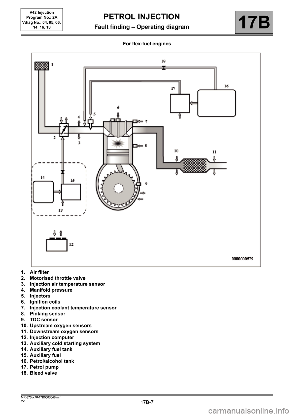
For flex-fuel engines
1. Air filter
2. Motorised throttle valve
3. Injection air temperature sensor
4. Manifold pressure
5. Injectors
6. Ignition coils
7. Injection coolant temperature sensor
8. Pinking sensor
9. TDC sensor
10. Upstream oxygen sensors
11. Downstream oxygen sensors
12. Injection computer
13. Auxiliary cold starting system
14. Auxiliary fuel tank
15. Auxiliary fuel
16. Petrol/alcohol tank
17. Petrol pump
18. Bleed valve
PETROL INJECTION
Fault finding – Operating diagram
Page 8 of 279
17B-8V2 MR-376-X76-17B050$040.mif
PETROL INJECTION
Fault finding – Operating diagram17B
V42 Injection
Program No.: 2A
Vdiag No.: 04, 05, 06,
14, 16, 18
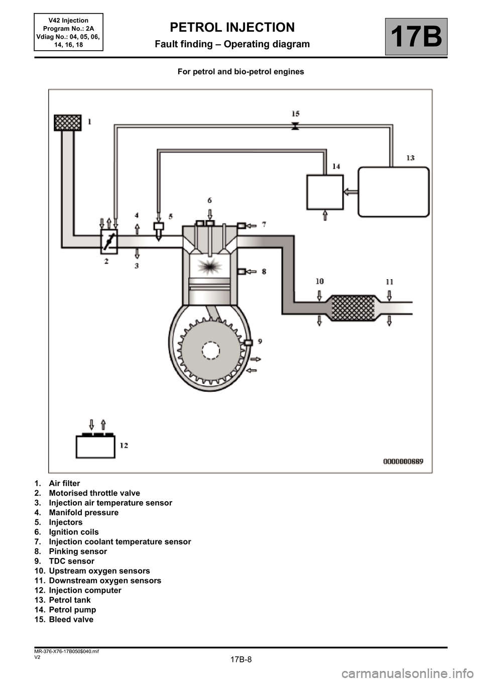
For petrol and bio-petrol engines
1. Air filter
2. Motorised throttle valve
3. Injection air temperature sensor
4. Manifold pressure
5. Injectors
6. Ignition coils
7. Injection coolant temperature sensor
8. Pinking sensor
9. TDC sensor
10. Upstream oxygen sensors
11. Downstream oxygen sensors
12. Injection computer
13. Petrol tank
14. Petrol pump
15. Bleed valve
Page 21 of 279
17B-21
AFTER REPAIRDeal with any faults displayed by the diagnostic tool.
Clear the computer fault memory.
Carry out a road test followed by another check with the diagnostic tool.
V2 MR-376-X76-17B050$081.mif
17B
V42 Injection
Program No.: 2A
Vdiag No.: 04, 05, 06,
14, 16, 18
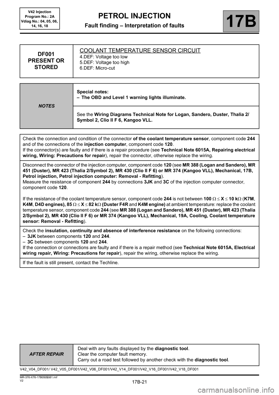
DF001
PRESENT OR
STOREDCOOLANT TEMPERATURE SENSOR CIRCUIT4.DEF: Voltage too low
5.DEF: Voltage too high
6.DEF: Micro-cut
NOTESSpecial notes:
– The OBD and Level 1 warning lights illuminate.
See the Wiring Diagrams Technical Note for Logan, Sandero, Duster, Thalia 2/
Symbol 2, Clio II F 6, Kangoo VLL.
Check the connection and condition of the connector of the coolant temperature sensor, component code 244
and of the connections of the injection computer, component code 120.
If the connector(s) are faulty and if there is a repair procedure (see Technical Note 6015A, Repairing electrical
wiring, Wiring: Precautions for repair), repair the connector, otherwise replace the wiring.
Disconnect the connector of the injection computer, component code 120 (see MR 388 (Logan and Sandero), MR
451 (Duster), MR 423 (Thalia 2/Symbol 2), MR 430 (Clio II F 6) or MR 374 (Kangoo VLL), Mechanical, 17B,
Petrol injection, Petrol injection computer: Removal - Refitting).
Measure the resistance of component 244 by connections 3JK and 3C of the injection computer connector,
component code 120.
If the resistance of the coolant temperature sensor, component code 244 is not between 100 X 10 k (K7M,
K4M, D4D engines), 85 X 82 k (Duster F4R and K4M engine) at ambient temperature: replace the coolant
temperature sensor, component code 244 (see MR 388 (Logan and Sandero), MR 451 (Duster), MR 423 (Thalia
2/Symbol 2), MR 430 (Clio II F 6) or MR 374 (Kangoo VLL), Mechanical, 19A, Cooling, Coolant temperature
sensor: Removal - Refitting).
Check the insulation, continuity and absence of interference resistance on the following connections:
–3JK between components 120 and 244.
–3C between components 120 and 244.
If the connection or connections are faulty and if there is a repair method (see Technical Note 6015A, Electrical
wiring repair, Wiring: Precautions for repair), repair the wiring, otherwise replace the wiring.
If the fault is still present, contact the Techline.
V42_V04_DF001/ V42_V05_DF001/V42_V06_DF001/V42_V14_DF001/V42_V16_DF001/V42_V18_DF001
PETROL INJECTION
Fault finding – Interpretation of faults
Page 22 of 279
17B-22
AFTER REPAIRDeal with any faults displayed by the diagnostic tool.
Clear the computer fault memory.
Carry out a road test followed by another check with the diagnostic tool.
V2 MR-376-X76-17B050$081.mif
PETROL INJECTION
Fault finding – Interpretation of faults17B
V42 Injection
Program No.: 2A
Vdiag No.: 04, 05, 06,
14, 16, 18
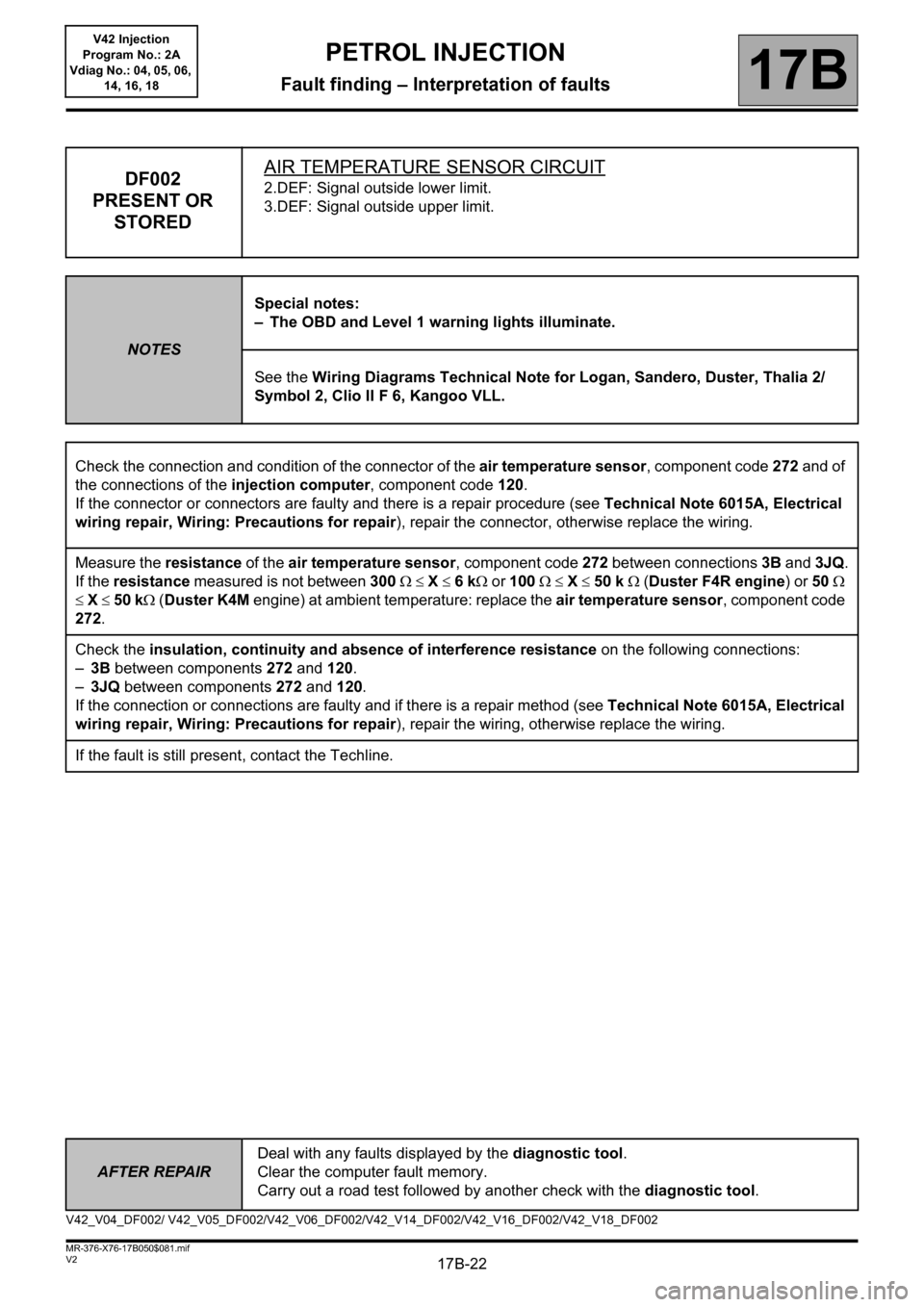
DF002
PRESENT OR
STOREDAIR TEMPERATURE SENSOR CIRCUIT2.DEF: Signal outside lower limit.
3.DEF: Signal outside upper limit.
NOTESSpecial notes:
– The OBD and Level 1 warning lights illuminate.
See the Wiring Diagrams Technical Note for Logan, Sandero, Duster, Thalia 2/
Symbol 2, Clio II F 6, Kangoo VLL.
Check the connection and condition of the connector of the air temperature sensor, component code 272 and of
the connections of the injection computer, component code 120.
If the connector or connectors are faulty and there is a repair procedure (see Technical Note 6015A, Electrical
wiring repair, Wiring: Precautions for repair), repair the connector, otherwise replace the wiring.
Measure the resistance of the air temperature sensor, component code 272 between connections 3B and 3JQ.
If the resistance measured is not between 300 X 6 k or 100 X 50 k (Duster F4R engine) or 50
X 50 k (Duster K4M engine) at ambient temperature: replace the air temperature sensor, component code
272.
Check the insulation, continuity and absence of interference resistance on the following connections:
–3B between components 272 and 120.
–3JQ between components 272 and 120.
If the connection or connections are faulty and if there is a repair method (see Technical Note 6015A, Electrical
wiring repair, Wiring: Precautions for repair
), repair the wiring, otherwise replace the wiring.
If the fault is still present, contact the Techline.
V42_V04_DF002/ V42_V05_DF002/V42_V06_DF002/V42_V14_DF002/V42_V16_DF002/V42_V18_DF002
Page 23 of 279
17B-23
AFTER REPAIRDeal with any faults displayed by the diagnostic tool.
Clear the computer fault memory.
Carry out a road test followed by another check with the diagnostic tool.
V2 MR-376-X76-17B050$081.mif
PETROL INJECTION
Fault finding – Interpretation of faults17B
V42 Injection
Program No.: 2A
Vdiag No.: 04, 05, 06,
14, 16, 18
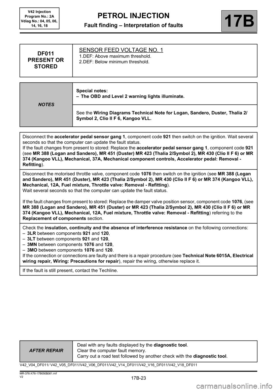
DF011
PRESENT OR
STOREDSENSOR FEED VOLTAGE NO. 11.DEF: Above maximum threshold.
2.DEF: Below minimum threshold.
NOTESSpecial notes:
– The OBD and Level 2 warning lights illuminate.
See the Wiring Diagrams Technical Note for Logan, Sandero, Duster, Thalia 2/
Symbol 2, Clio II F 6, Kangoo VLL.
Disconnect the accelerator pedal sensor gang 1, component code 921 then switch on the ignition. Wait several
seconds so that the computer can update the fault status.
If the fault changes from present to stored: Replace the accelerator pedal sensor gang 1, component code 921
(see MR 388 (Logan and Sandero), MR 451 (Duster) MR 423 (Thalia 2/Symbol 2), MR 430 (Clio II F 6) or MR
374 (Kangoo VLL), Mechanical, 37A, Mechanical component controls, Accelerator pedal: Removal -
Refitting).
Disconnect the motorised throttle valve, component code 1076 then switch on the ignition (see MR 388 (Logan
and Sandero), MR 451 (Duster), MR 423 (Thalia 2/Symbol 2), MR 430 (Clio II F 6) or MR 374 (Kangoo VLL),
Mechanical, 12A, Fuel mixture, Throttle valve: Removal - Refitting).
Wait several seconds so that the computer can update the fault status.
If the fault changes from present to stored: Replace the damper valve position sensor, component code 1076, (see
MR 388 (Logan and Sandero), MR 451 (Duster) or MR 423 (Thalia 2/Symbol 2), MR 430 (Clio II F 6) or MR
374 (Kangoo VLL), Mechanical, 12A, Fuel mixture, Throttle valve: Removal - Refitting) referring to the
Replacement of components section.
Check the insulation, continuity and the absence of interference resistance on the following connections:
–3LR between components 921 and 120,
–3LT between components 921 and 120,
–3MN between components 1076 and 120,
–3MO between components 1076 and 120.
If the connection or connections are faulty and there is a repair procedure (see Technical Note 6015A, Electrical
wiring repair, Wiring: Precautions for repair), repair the wiring, otherwise replace it.
If the fault is still present, contact the Techline.
V42_V04_DF011/ V42_V05_DF011/V42_V06_DF011/V42_V14_DF011/V42_V16_DF011/V42_V18_DF011
Page 24 of 279
17B-24
AFTER REPAIRDeal with any faults displayed by the diagnostic tool.
Clear the computer fault memory.
Carry out a road test followed by another check with the diagnostic tool.
V2 MR-376-X76-17B050$081.mif
PETROL INJECTION
Fault finding – Interpretation of faults17B
V42 Injection
Program No.: 2A
Vdiag No.: 04, 05, 06,
14, 16, 18
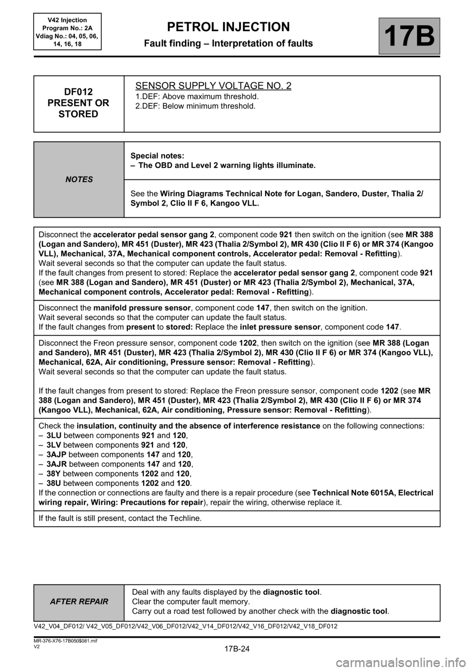
DF012
PRESENT OR
STOREDSENSOR SUPPLY VOLTAGE NO. 21.DEF: Above maximum threshold.
2.DEF: Below minimum threshold.
NOTESSpecial notes:
– The OBD and Level 2 warning lights illuminate.
See the Wiring Diagrams Technical Note for Logan, Sandero, Duster, Thalia 2/
Symbol 2, Clio II F 6, Kangoo VLL.
Disconnect the accelerator pedal sensor gang 2, component code 921 then switch on the ignition (see MR 388
(Logan and Sandero), MR 451 (Duster), MR 423 (Thalia 2/Symbol 2), MR 430 (Clio II F 6) or MR 374 (Kangoo
VLL), Mechanical, 37A, Mechanical component controls, Accelerator pedal: Removal - Refitting).
Wait several seconds so that the computer can update the fault status.
If the fault changes from present to stored: Replace the accelerator pedal sensor gang 2, component code 921
(see MR 388 (Logan and Sandero), MR 451 (Duster) or MR 423 (Thalia 2/Symbol 2), Mechanical, 37A,
Mechanical component controls, Accelerator pedal: Removal - Refitting).
Disconnect the manifold pressure sensor, component code 147, then switch on the ignition.
Wait several seconds so that the computer can update the fault status.
If the fault changes from present to stored: Replace the inlet pressure sensor, component code 147.
Disconnect the Freon pressure sensor, component code 1202, then switch on the ignition (see MR 388 (Logan
and Sandero), MR 451 (Duster), MR 423 (Thalia 2/Symbol 2), MR 430 (Clio II F 6) or MR 374 (Kangoo VLL),
Mechanical, 62A, Air conditioning, Pressure sensor: Removal - Refitting).
Wait several seconds so that the computer can update the fault status.
If the fault changes from present to stored: Replace the Freon pressure sensor, component code 1202 (see MR
388 (Logan and Sandero), MR 451 (Duster), MR 423 (Thalia 2/Symbol 2), MR 430 (Clio II F 6) or MR 374
(Kangoo VLL), Mechanical, 62A, Air conditioning, Pressure sensor: Removal - Refitting).
Check the insulation, continuity and the absence of interference resistance on the following connections:
–3LU between components 921 and 120,
–3LV between components 921 and 120,
–3AJP between components 147 and 120,
–3AJR between components 147 and 120,
–38Y between components 1202 and 120,
–38U between components 1202 and 120.
If the connection or connections are faulty and there is a repair procedure (see Technical Note 6015A, Electrical
wiring repair, Wiring: Precautions for repair), repair the wiring, otherwise replace it.
If the fault is still present, contact the Techline.
V42_V04_DF012/ V42_V05_DF012/V42_V06_DF012/V42_V14_DF012/V42_V16_DF012/V42_V18_DF012
Page 25 of 279
17B-25
AFTER REPAIRDeal with any faults displayed by the diagnostic tool.
Clear the computer fault memory.
Carry out a road test followed by another check with the diagnostic tool.
V2 MR-376-X76-17B050$081.mif
PETROL INJECTION
Fault finding – Interpretation of faults17B
V42 Injection
Program No.: 2A
Vdiag No.: 04, 05, 06,
14, 16, 18
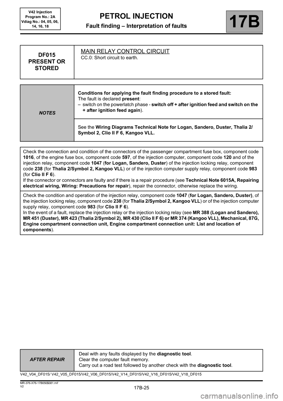
DF015
PRESENT OR
STOREDMAIN RELAY CONTROL CIRCUITCC.0: Short circuit to earth.
NOTESConditions for applying the fault finding procedure to a stored fault:
The fault is declared present:
– switch on the powerlatch phase - switch off + after ignition feed and switch on the
+ after ignition feed again).
See the Wiring Diagrams Technical Note for Logan, Sandero, Duster, Thalia 2/
Symbol 2, Clio II F 6, Kangoo VLL.
Check the connection and condition of the connectors of the passenger compartment fuse box, component code
1016, of the engine fuse box, component code 597, of the injection computer, component code 120 and of the
injection relay, component code 1047 (for Logan, Sandero, Duster) of the injection locking relay, component
code 238 (for Thalia 2/Symbol 2, Kangoo VLL) or of the injection computer supply relay, component code 983
(for Clio II F 6).
If the connector or connectors are faulty and if there is a repair procedure (see Technical Note 6015A, Repairing
electrical wiring, Wiring: Precautions for repair), repair the connector, otherwise replace the wiring.
Check the condition and operation of the injection relay, component code 1047 (for Logan, Sandero, Duster), of
the injection locking relay, component code 238 (for Thalia 2/Symbol 2, Kangoo VLL) or of the injection computer
supply relay, component code 983 (for Clio II F 6).
In the event of a fault, replace the injection relay or the injection locking relay (see MR 388 (Logan and Sandero),
MR 451 (Duster), MR 423 (Thalia 2/Symbol 2), MR 430 (Clio II F 6) or MR 374 (Kangoo VLL), Mechanical, 87G,
Engine compartment connection unit, Engine compartment connection unit: List and location of
components).
V42_V04_DF015/ V42_V05_DF015/V42_V06_DF015/V42_V14_DF015/V42_V16_DF015/V42_V18_DF015
Page 27 of 279
17B-27
AFTER REPAIRDeal with any faults displayed by the diagnostic tool.
Clear the computer fault memory.
Carry out a road test followed by another check with the diagnostic tool.
V2 MR-376-X76-17B050$081.mif
PETROL INJECTION
Fault finding – Interpretation of faults17B
V42 Injection
Program No.: 2A
Vdiag No.: 04, 05, 06,
14, 16, 18
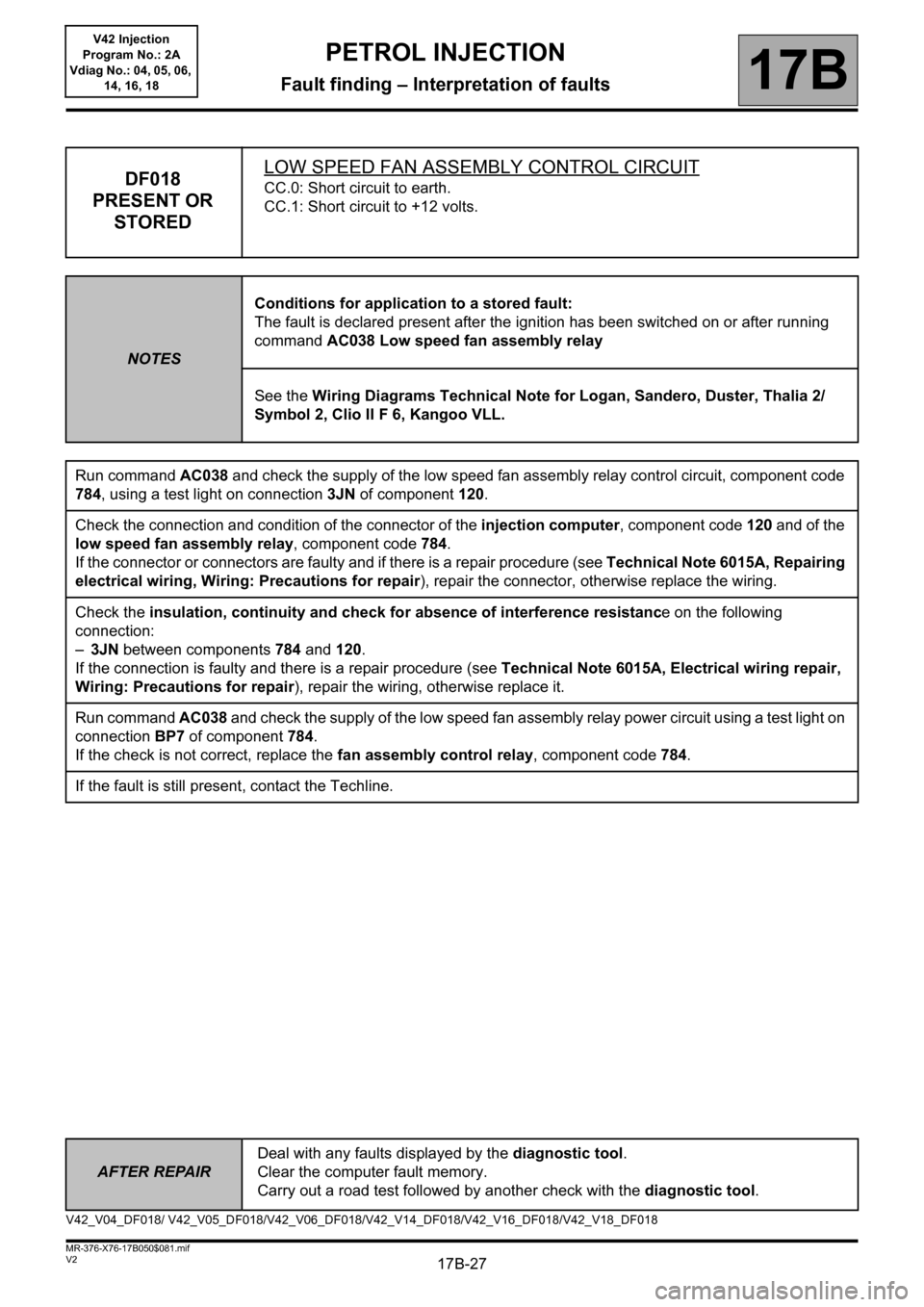
DF018
PRESENT OR
STOREDLOW SPEED FAN ASSEMBLY CONTROL CIRCUITCC.0: Short circuit to earth.
CC.1: Short circuit to +12 volts.
NOTESConditions for application to a stored fault:
The fault is declared present after the ignition has been switched on or after running
command AC038 Low speed fan assembly relay
See the Wiring Diagrams Technical Note for Logan, Sandero, Duster, Thalia 2/
Symbol 2, Clio II F 6, Kangoo VLL.
Run command AC038 and check the supply of the low speed fan assembly relay control circuit, component code
784, using a test light on connection 3JN of component 120.
Check the connection and condition of the connector of the injection computer, component code 120 and of the
low speed fan assembly relay, component code 784.
If the connector or connectors are faulty and if there is a repair procedure (see Technical Note 6015A, Repairing
electrical wiring, Wiring: Precautions for repair), repair the connector, otherwise replace the wiring.
Check the insulation, continuity and check for absence of interference resistance on the following
connection:
–3JN between components 784 and 120.
If the connection is faulty and there is a repair procedure (see Technical Note 6015A, Electrical wiring repair,
Wiring: Precautions for repair), repair the wiring, otherwise replace it.
Run command AC038 and check the supply of the low speed fan assembly relay power circuit using a test light on
connection BP7 of component 784.
If the check is not correct, replace the fan assembly control relay, component code 784.
If the fault is still present, contact the Techline.
V42_V04_DF018/ V42_V05_DF018/V42_V06_DF018/V42_V14_DF018/V42_V16_DF018/V42_V18_DF018