brake switch signal RENAULT KANGOO 2013 X61 / 2.G Petrol V42 Injection Workshop Manual
[x] Cancel search | Manufacturer: RENAULT, Model Year: 2013, Model line: KANGOO, Model: RENAULT KANGOO 2013 X61 / 2.GPages: 279, PDF Size: 1.29 MB
Page 5 of 279
17B-5V2 MR-376-X76-17B050$030.mif
17B
V42 Injection
Program No.: 2A
Vdiag No.: 04, 05, 06,
14, 16, 18
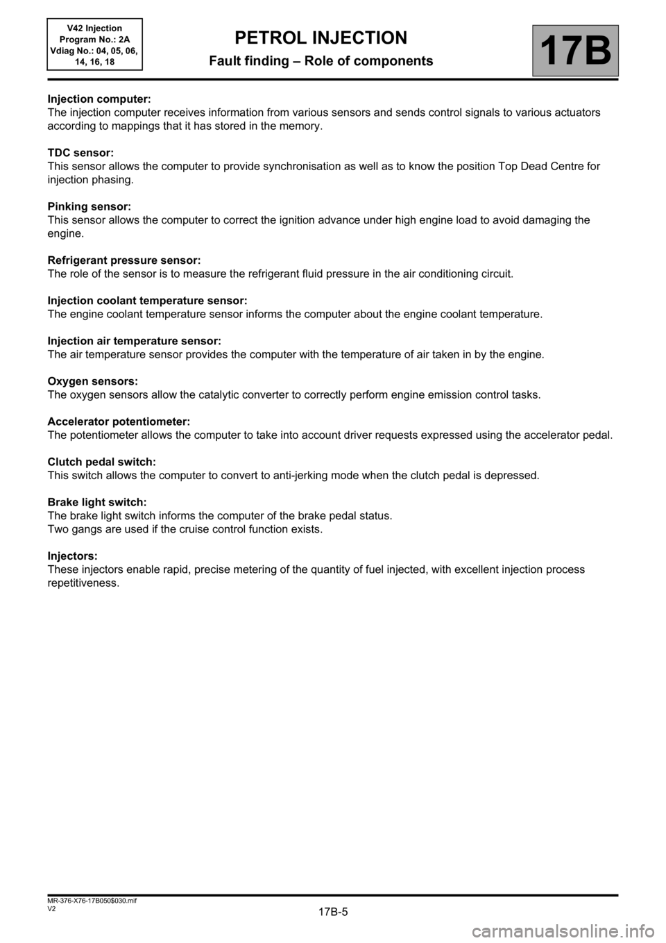
Injection computer:
The injection computer receives information from various sensors and sends control signals to various actuators
according to mappings that it has stored in the memory.
TDC sensor:
This sensor allows the computer to provide synchronisation as well as to know the position Top Dead Centre for
injection phasing.
Pinking sensor:
This sensor allows the computer to correct the ignition advance under high engine load to avoid damaging the
engine.
Refrigerant pressure sensor:
The role of the sensor is to measure the refrigerant fluid pressure in the air conditioning circuit.
Injection coolant temperature sensor:
The engine coolant temperature sensor informs the computer about the engine coolant temperature.
Injection air temperature sensor:
The air temperature sensor provides the computer with the temperature of air taken in by the engine.
Oxygen sensors:
The oxygen sensors allow the catalytic converter to correctly perform engine emission control tasks.
Accelerator potentiometer:
The potentiometer allows the computer to take into account driver requests expressed using the accelerator pedal.
Clutch pedal switch:
This switch allows the computer to convert to anti-jerking mode when the clutch pedal is depressed.
Brake light switch:
The brake light switch informs the computer of the brake pedal status.
Two gangs are used if the cruise control function exists.
Injectors:
These injectors enable rapid, precise metering of the quantity of fuel injected, with excellent injection process
repetitiveness.
PETROL INJECTION
Fault finding – Role of components
Page 18 of 279
17B-18V2 MR-376-X76-17B050$070.mif
PETROL INJECTION
Fault finding – Fault summary table17B
V42 Injection
Program No.: 2A
Vdiag No.: 04, 05, 06,
14, 16, 18
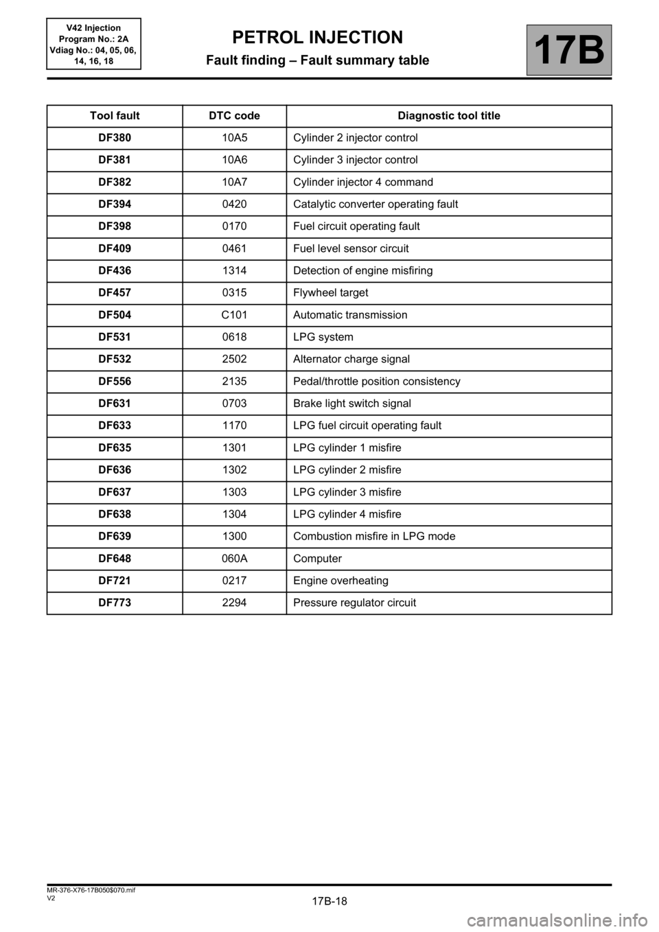
Tool fault DTC code Diagnostic tool title
DF38010A5 Cylinder 2 injector control
DF38110A6 Cylinder 3 injector control
DF38210A7 Cylinder injector 4 command
DF3940420 Catalytic converter operating fault
DF3980170 Fuel circuit operating fault
DF4090461 Fuel level sensor circuit
DF4361314 Detection of engine misfiring
DF4570315 Flywheel target
DF504C101 Automatic transmission
DF5310618 LPG system
DF5322502 Alternator charge signal
DF5562135 Pedal/throttle position consistency
DF6310703 Brake light switch signal
DF6331170 LPG fuel circuit operating fault
DF6351301 LPG cylinder 1 misfire
DF6361302 LPG cylinder 2 misfire
DF6371303 LPG cylinder 3 misfire
DF6381304 LPG cylinder 4 misfire
DF6391300 Combustion misfire in LPG mode
DF648060A Computer
DF7210217 Engine overheating
DF7732294 Pressure regulator circuit
Page 19 of 279
17B-19V2 MR-376-X76-17B050$070.mif
PETROL INJECTION
Fault finding – Fault summary table17B
V42 Injection
Program No.: 2A
Vdiag No.: 04, 05, 06,
14, 16, 18
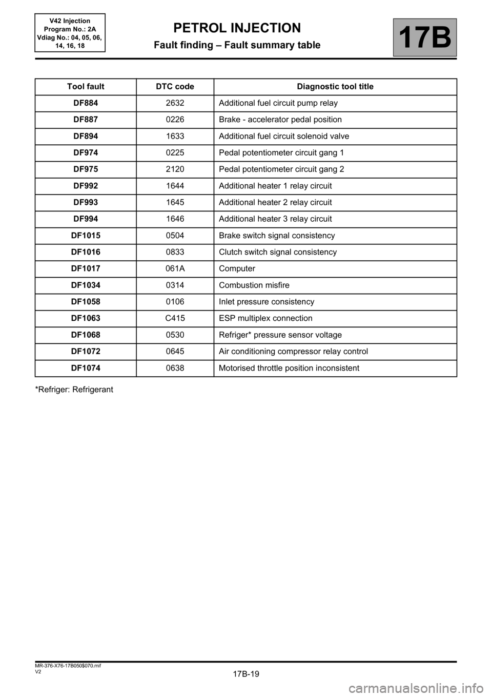
*Refriger: RefrigerantTool fault DTC code Diagnostic tool title
DF8842632 Additional fuel circuit pump relay
DF8870226 Brake - accelerator pedal position
DF8941633 Additional fuel circuit solenoid valve
DF9740225 Pedal potentiometer circuit gang 1
DF9752120 Pedal potentiometer circuit gang 2
DF9921644 Additional heater 1 relay circuit
DF9931645 Additional heater 2 relay circuit
DF9941646 Additional heater 3 relay circuit
DF10150504 Brake switch signal consistency
DF10160833 Clutch switch signal consistency
DF1017061A Computer
DF10340314 Combustion misfire
DF10580106 Inlet pressure consistency
DF1063C415 ESP multiplex connection
DF10680530 Refriger* pressure sensor voltage
DF10720645 Air conditioning compressor relay control
DF10740638 Motorised throttle position inconsistent
Page 39 of 279
17B-39
AFTER REPAIRDeal with any faults displayed by the diagnostic tool.
Clear the computer fault memory.
Carry out a road test followed by another check with the diagnostic tool.
V2 MR-376-X76-17B050$081.mif
PETROL INJECTION
Fault finding – Interpretation of faults17B
V42 Injection
Program No.: 2A
Vdiag No.: 04, 05, 06,
14, 16, 18
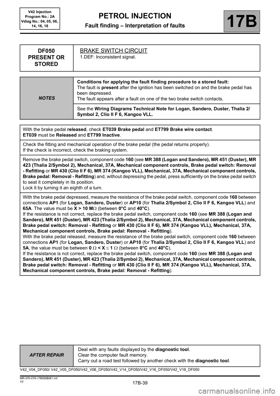
DF050
PRESENT OR
STOREDBRAKE SWITCH CIRCUIT
1.DEF: Inconsistent signal.
NOTESConditions for applying the fault finding procedure to a stored fault:
The fault is present after the ignition has been switched on and the brake pedal has
been depressed.
The fault appears after a fault on one of the two brake switch contacts.
See the Wiring Diagrams Technical Note for Logan, Sandero, Duster, Thalia 2/
Symbol 2, Clio II F 6, Kangoo VLL.
With the brake pedal released, check ET039 Brake pedal and ET799 Brake wire contact.
ET039 must be Released and ET799 Inactive.
Check the fitting and mechanical operation of the brake pedal (the pedal returns properly).
If the check is incorrect, check the braking system.
Remove the brake pedal switch, component code 160 (see MR 388 (Logan and Sandero), MR 451 (Duster), MR
423 (Thalia 2/Symbol 2), Mechanical, 37A, Mechanical component controls, Brake pedal switch: Removal
- Refitting or MR 430 (Clio II F 6), MR 374 (Kangoo VLL), Mechanical, 37A, Mechanical component controls,
Brake pedal: Removal - Refitting) and, without depressing the pedal, press sufficiently on the brake pedal switch
to seat it completely in its position.
Lock it by turning it an eighth of a turn.
With the brake pedal depressed, measure the resistance of the brake pedal switch, component code 160 between
connections AP1 (for Logan, Sandero, Duster) or AP10 (for Thalia 2/Symbol 2, Clio II F 6, Kangoo VLL) and
65A. The value must be X > 10 M (between 0°C and 40°C).
If the resistance is not correct, replace the brake pedal switch, component code 160 (see MR 388 (Logan and
Sandero), MR 451 (Duster), MR 423 (Thalia 2/Symbol 2), Mechanical, 37A, Mechanical component controls,
Brake pedal switch: Removal - Refitting or MR 430 (Clio II F 6), MR 374 (Kangoo VLL), Mechanical, 37A,
Mechanical component controls, Brake pedal: Removal - Refitting).
With the brake pedal released, measure the resistance of the brake pedal switch, component code 160 between
connections AP1 (for Logan, Sandero, Duster) or AP10 (for Thalia 2/Symbol 2, Clio II F 6, Kangoo VLL) and
5A, the value must be between 0 < X 1 (between 0°C and 40°C).
If the resistance is not correct, replace the brake pedal switch, component code 160 (see MR 388 (Logan and
Sandero), MR 451 (Duster), MR 423 (Thalia 2/Symbol 2), Mechanical, 37A, Mechanical component controls,
Brake pedal switch: Removal - Refitting or MR 430 (Clio II F 6), MR 374 (Kangoo VLL), Mechanical, 37A,
Mechanical component controls, Brake pedal: Removal - Refitting).
V42_V04_DF050/ V42_V05_DF050/V42_V06_DF050/V42_V14_DF050/V42_V16_DF050/V42_V18_DF050
Page 101 of 279
17B-101
AFTER REPAIRDeal with any faults displayed by the diagnostic tool.
Clear the computer fault memory.
Carry out a road test followed by another check with the diagnostic tool.
V2 MR-376-X76-17B050$083.mif
PETROL INJECTION
Fault finding – Interpretation of faults17B
V42 Injection
Program No.: 2A
Vdiag No.: 04, 05, 06,
14, 16, 18
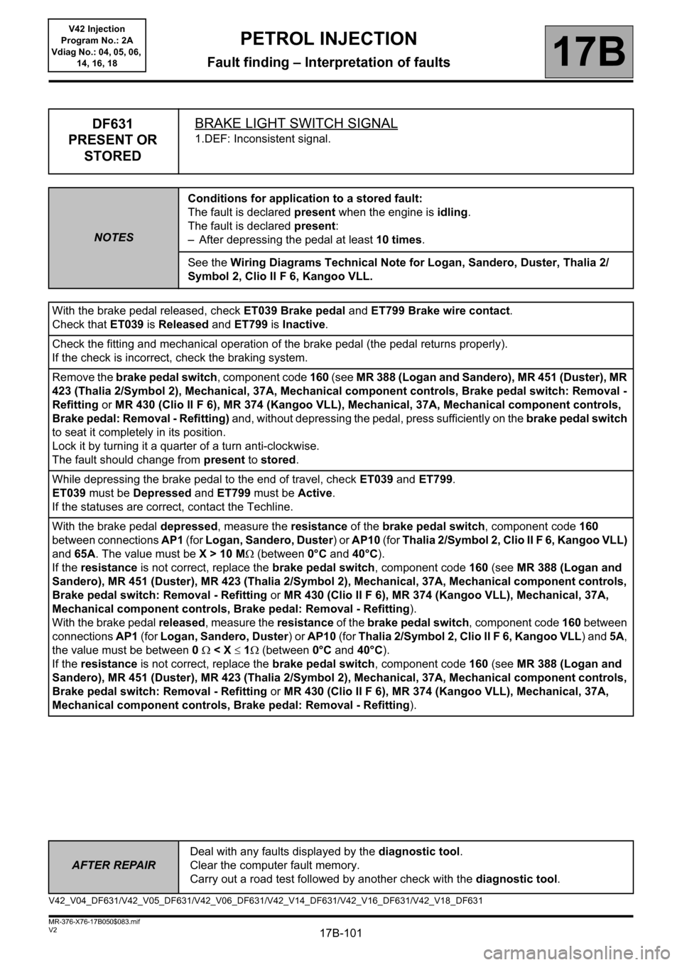
DF631
PRESENT OR
STOREDBRAKE LIGHT SWITCH SIGNAL
1.DEF: Inconsistent signal.
NOTESConditions for application to a stored fault:
The fault is declared present when the engine is idling.
The fault is declared present:
– After depressing the pedal at least 10 times.
See the Wiring Diagrams Technical Note for Logan, Sandero, Duster, Thalia 2/
Symbol 2, Clio II F 6, Kangoo VLL.
With the brake pedal released, check ET039 Brake pedal and ET799 Brake wire contact.
Check that ET039 is Released and ET799 is Inactive.
Check the fitting and mechanical operation of the brake pedal (the pedal returns properly).
If the check is incorrect, check the braking system.
Remove the brake pedal switch, component code 160 (see MR 388 (Logan and Sandero), MR 451 (Duster), MR
423 (Thalia 2/Symbol 2), Mechanical, 37A, Mechanical component controls, Brake pedal switch: Removal -
Refitting or MR 430 (Clio II F 6), MR 374 (Kangoo VLL), Mechanical, 37A, Mechanical component controls,
Brake pedal: Removal - Refitting) and, without depressing the pedal, press sufficiently on the brake pedal switch
to seat it completely in its position.
Lock it by turning it a quarter of a turn anti-clockwise.
The fault should change from present to stored.
While depressing the brake pedal to the end of travel, check ET039 and ET799.
ET039 must be Depressed and ET799 must be Active.
If the statuses are correct, contact the Techline.
With the brake pedal depressed, measure the resistance of the brake pedal switch, component code 160
between connections AP1 (for Logan, Sandero, Duster) or AP10 (for Thalia 2/Symbol 2, Clio II F 6, Kangoo VLL)
and 65A. The value must be X > 10 M (between 0°C and 40°C).
If the resistance is not correct, replace the brake pedal switch, component code 160 (see MR 388 (Logan and
Sandero), MR 451 (Duster), MR 423 (Thalia 2/Symbol 2), Mechanical, 37A, Mechanical component controls,
Brake pedal switch: Removal - Refitting or MR 430 (Clio II F 6), MR 374 (Kangoo VLL), Mechanical, 37A,
Mechanical component controls, Brake pedal: Removal - Refitting).
With the brake pedal released, measure the resistance of the brake pedal switch, component code 160 between
connections AP1 (for Logan, Sandero, Duster) or AP10 (for Thalia 2/Symbol 2, Clio II F 6, Kangoo VLL) and 5A,
the value must be between 0 < X 1 (between 0°C and 40°C).
If the resistance is not correct, replace the brake pedal switch, component code 160 (see MR 388 (Logan and
Sandero), MR 451 (Duster), MR 423 (Thalia 2/Symbol 2), Mechanical, 37A, Mechanical component controls,
Brake pedal switch: Removal - Refitting or MR 430 (Clio II F 6), MR 374 (Kangoo VLL), Mechanical, 37A,
Mechanical component controls, Brake pedal: Removal - Refitting).
V42_V04_DF631/V42_V05_DF631/V42_V06_DF631/V42_V14_DF631/V42_V16_DF631/V42_V18_DF631
Page 134 of 279
17B-134
AFTER REPAIRDeal with any faults displayed by the diagnostic tool.
Clear the computer fault memory.
Carry out a road test followed by another check with the diagnostic tool.
V2 MR-376-X76-17B050$084.mif
PETROL INJECTION
Fault finding – Interpretation of faults17B
V42 Injection
Program No.: 2A
Vdiag No.: 04, 05, 06,
14, 16, 18
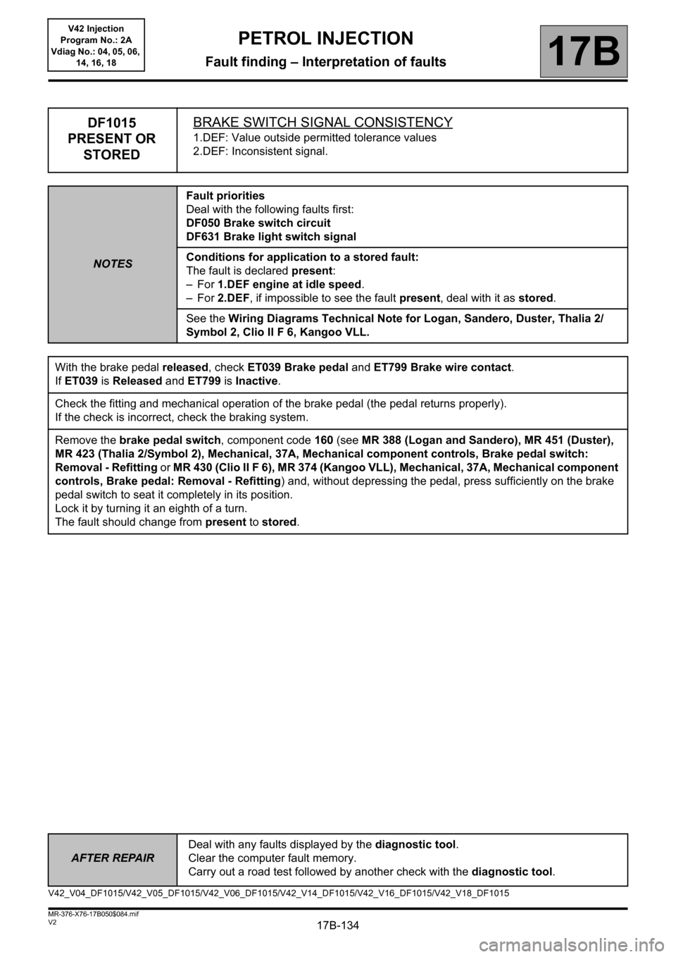
DF1015
PRESENT OR
STOREDBRAKE SWITCH SIGNAL CONSISTENCY
1.DEF: Value outside permitted tolerance values
2.DEF: Inconsistent signal.
NOTESFault priorities
Deal with the following faults first:
DF050 Brake switch circuit
DF631 Brake light switch signal
Conditions for application to a stored fault:
The fault is declared present:
–For 1.DEF engine at idle speed.
–For 2.DEF, if impossible to see the fault present, deal with it as stored.
See the Wiring Diagrams Technical Note for Logan, Sandero, Duster, Thalia 2/
Symbol 2, Clio II F 6, Kangoo VLL.
With the brake pedal released, check ET039 Brake pedal and ET799 Brake wire contact.
If ET039 is Released and ET799 is Inactive.
Check the fitting and mechanical operation of the brake pedal (the pedal returns properly).
If the check is incorrect, check the braking system.
Remove the brake pedal switch, component code 160 (see MR 388 (Logan and Sandero), MR 451 (Duster),
MR 423 (Thalia 2/Symbol 2), Mechanical, 37A, Mechanical component controls, Brake pedal switch:
Removal - Refitting or MR 430 (Clio II F 6), MR 374 (Kangoo VLL), Mechanical, 37A, Mechanical component
controls, Brake pedal: Removal - Refitting) and, without depressing the pedal, press sufficiently on the brake
pedal switch to seat it completely in its position.
Lock it by turning it an eighth of a turn.
The fault should change from present to stored.
V42_V04_DF1015/V42_V05_DF1015/V42_V06_DF1015/V42_V14_DF1015/V42_V16_DF1015/V42_V18_DF1015
Page 161 of 279
17B-161V2 MR-376-X76-17B050$100.mif
17B
V42 Injection
Program No.: 2A
Vdiag No.: 04, 05, 06,
14, 16, 18
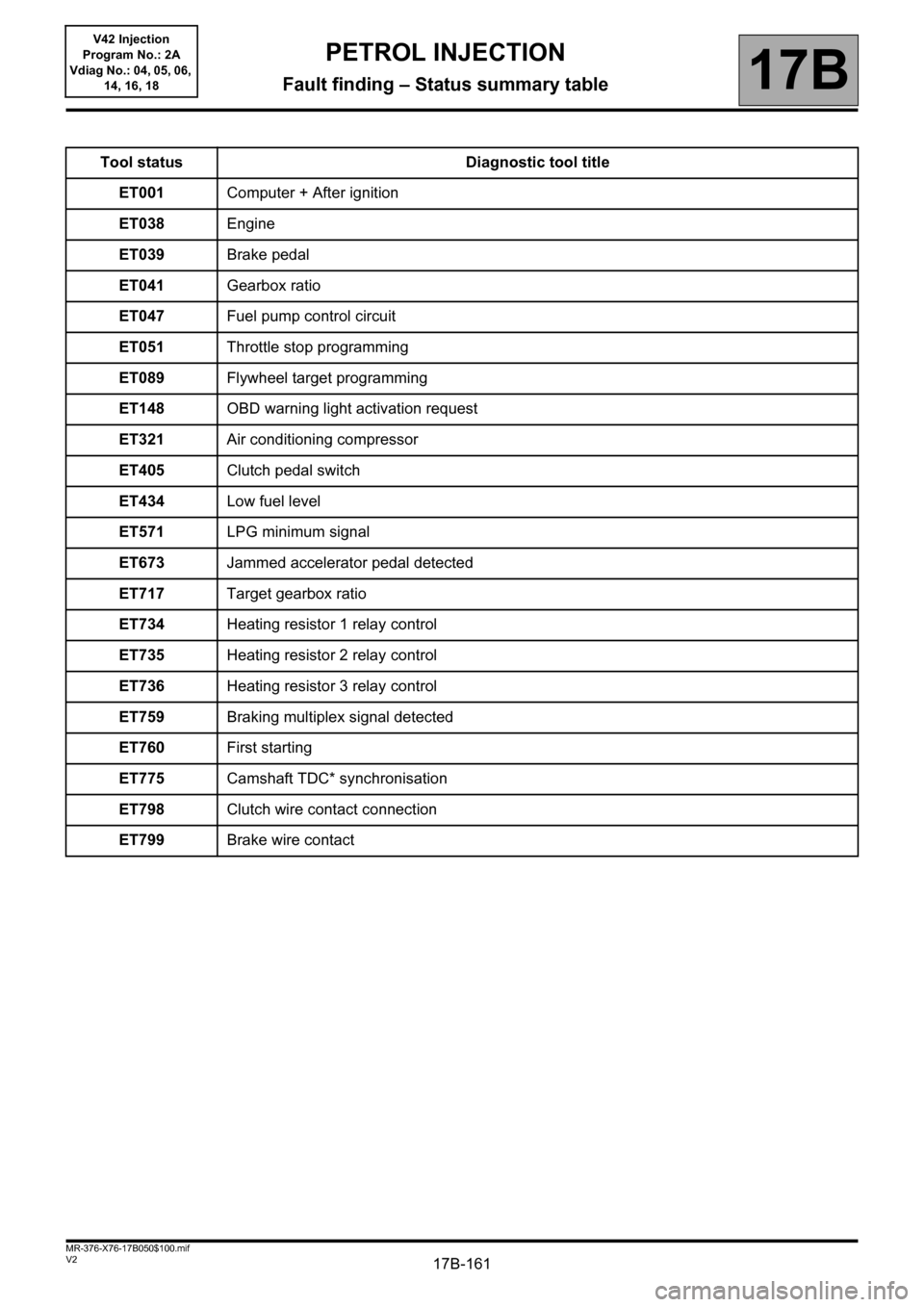
Tool status Diagnostic tool title
ET001Computer + After ignition
ET038Engine
ET039Brake pedal
ET041Gearbox ratio
ET047Fuel pump control circuit
ET051Throttle stop programming
ET089Flywheel target programming
ET148OBD warning light activation request
ET321Air conditioning compressor
ET405Clutch pedal switch
ET434Low fuel level
ET571LPG minimum signal
ET673Jammed accelerator pedal detected
ET717Target gearbox ratio
ET734Heating resistor 1 relay control
ET735Heating resistor 2 relay control
ET736Heating resistor 3 relay control
ET759Braking multiplex signal detected
ET760First starting
ET775Camshaft TDC* synchronisation
ET798Clutch wire contact connection
ET799Brake wire contact
PETROL INJECTION
Fault finding – Status summary table
Page 176 of 279
17B-176V2 MR-376-X76-17B050$110.mif
PETROL INJECTION
Fault finding – Interpretation of statuses17B
V42 Injection
Program No.: 2A
Vdiag No.: 04, 05, 06,
14, 16, 18
AFTER REPAIRDeal with any faults. Clear the faults from the computer memory.
Switch off the ignition and carry out a road test followed by a test with the diagnostic
tool.
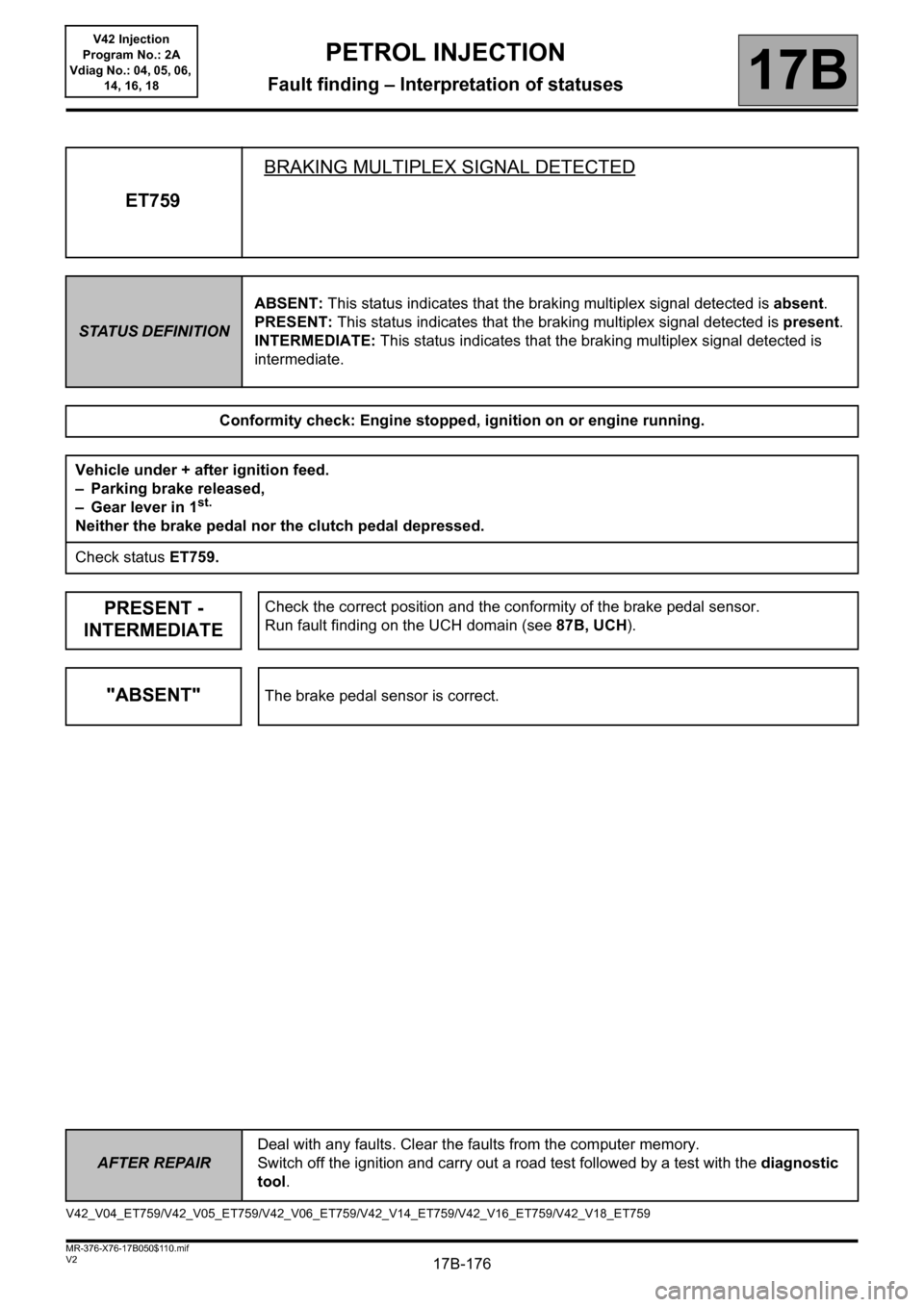
ET759BRAKING MULTIPLEX SIGNAL DETECTED
STATUS DEFINITIONABSENT: This status indicates that the braking multiplex signal detected is absent.
PRESENT: This status indicates that the braking multiplex signal detected is present.
INTERMEDIATE: This status indicates that the braking multiplex signal detected is
intermediate.
Conformity check: Engine stopped, ignition on or engine running.
Vehicle under + after ignition feed.
– Parking brake released,
– Gear lever in 1
st.
Neither the brake pedal nor the clutch pedal depressed.
Check status ET759.
PRESENT -
INTERMEDIATECheck the correct position and the conformity of the brake pedal sensor.
Run fault finding on the UCH domain (see 87B, UCH).
"ABSENT"The brake pedal sensor is correct.
V42_V04_ET759/V42_V05_ET759/V42_V06_ET759/V42_V14_ET759/V42_V16_ET759/V42_V18_ET759
Page 243 of 279
17B-243
AFTER REPAIRCarry out a road test, then check with the diagnostic tool.
V2 MR-376-X76-17B050$160.mif
PETROL INJECTION
Fault finding – Fault Finding Chart17B
V42 Injection
Program No.: 2A
Vdiag No.: 04, 05, 06,
14, 16, 18
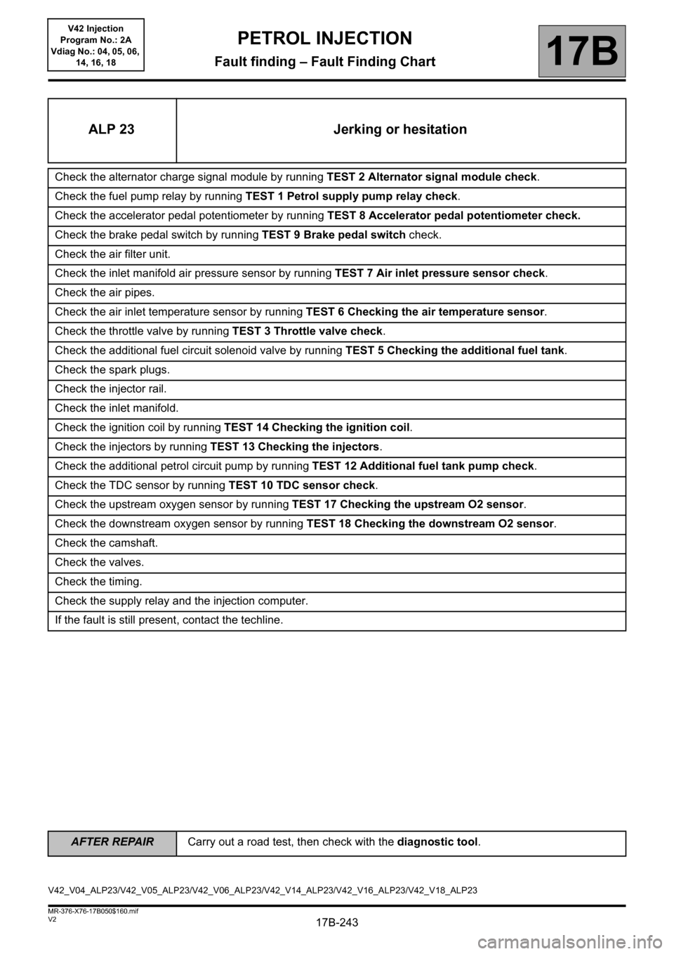
ALP 23 Jerking or hesitation
Check the alternator charge signal module by running TEST 2 Alternator signal module check.
Check the fuel pump relay by running TEST 1 Petrol supply pump relay check.
Check the accelerator pedal potentiometer by running TEST 8 Accelerator pedal potentiometer check.
Check the brake pedal switch by running TEST 9 Brake pedal switch check.
Check the air filter unit.
Check the inlet manifold air pressure sensor by running TEST 7 Air inlet pressure sensor check.
Check the air pipes.
Check the air inlet temperature sensor by running TEST 6 Checking the air temperature sensor.
Check the throttle valve by running TEST 3 Throttle valve check.
Check the additional fuel circuit solenoid valve by running TEST 5 Checking the additional fuel tank.
Check the spark plugs.
Check the injector rail.
Check the inlet manifold.
Check the ignition coil by running TEST 14 Checking the ignition coil.
Check the injectors by running TEST 13 Checking the injectors.
Check the additional petrol circuit pump by running TEST 12 Additional fuel tank pump check.
Check the TDC sensor by running TEST 10 TDC sensor check.
Check the upstream oxygen sensor by running TEST 17 Checking the upstream O2 sensor.
Check the downstream oxygen sensor by running TEST 18 Checking the downstream O2 sensor.
Check the camshaft.
Check the valves.
Check the timing.
Check the supply relay and the injection computer.
If the fault is still present, contact the techline.
V42_V04_ALP23/V42_V05_ALP23/V42_V06_ALP23/V42_V14_ALP23/V42_V16_ALP23/V42_V18_ALP23
Page 248 of 279
17B-248V2 MR-376-X76-17B050$170.mif
17B
V42 Injection
Program No.: 2A
Vdiag No.: 04, 05, 06,
14, 16, 18
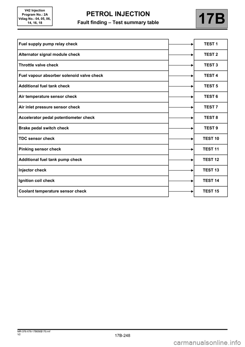
Fuel supply pump relay check TEST 1
Alternator signal module check TEST 2
Throttle valve checkTEST 3
Fuel vapour absorber solenoid valve check TEST 4
Additional fuel tank checkTEST 5
Air temperature sensor check TEST 6
Air inlet pressure sensor check TEST 7
Accelerator pedal potentiometer check TEST 8
Brake pedal switch checkTEST 9
TDC sensor checkTEST 10
Pinking sensor checkTEST 11
Additional fuel tank pump check TEST 12
Injector checkTEST 13
Ignition coil checkTEST 14
Coolant temperature sensor check TEST 15
PETROL INJECTION
Fault finding – Test summary table