display RENAULT KANGOO Z.E. 2018 Owner's Manual
[x] Cancel search | Manufacturer: RENAULT, Model Year: 2018, Model line: KANGOO Z.E., Model: RENAULT KANGOO Z.E. 2018Pages: 230, PDF Size: 5.03 MB
Page 112 of 230
2.12
TYRE PRESSURE LOSS WARNING (2/4)
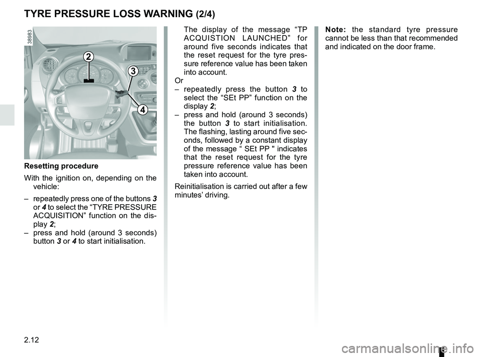
2
3
4
The display of the message “TP ACQUISTION LAUNCHED” for
around five seconds indicates that
the reset request for the tyre pres-
sure reference value has been taken
into account.
Or
– repeatedly press the button 3 to
select the “SEt PP” function on the
display 2;
– press and hold (around 3 seconds) the button 3 to start initialisation.
The flashing, lasting around five sec-
onds, followed by a constant display
of the message “ SEt PP " indicates
that the reset request for the tyre
pressure reference value has been
taken into account.
Reinitialisation is carried out after a few
minutes’ driving.
Resetting procedure
With the ignition on, depending on the vehicle:
– repeatedly press one of the buttons 3
or 4 to select the “TYRE PRESSURE
ACQUISITION” function on the dis-
play 2;
– press and hold (around 3 seconds) button 3 or 4 to start initialisation.
Note: the standard tyre pressure
cannot be less than that recommended
and indicated on the door frame.
Page 113 of 230
2.13
TYRE PRESSURE LOSS WARNING (3/4)
TYRE PUNCTURE
The warning light
stays on to-
gether with a beep and, depending
on the vehicle, the message “TYRE
PUNCTURE”.
This message is accompanied by the
warning light
®.
They indicate that at least one wheel
is punctured or severely underinfla-
ted. Replace it or contact an authorised
dealer if it is punctured. Top up the tyre
pressure if the wheel is deflated.
Warning light ® re-
quires you to stop immedi-
ately, for your own safety,
as soon as traffic conditions
allow.
The sudden loss of pressure in a
tyre (burst tyre, etc.) cannot be de-
tected by the system.
CHECK TYRE SENSORS
The warning light
flashes for
several seconds, then stays on and,
depending on the vehicle, together
with the message “CHECK TYRE
SENSORS ”.
This message is accompanied by the
warning light
©.
They indicate that at least one tyre is
not fitted with sensors (e.g. emergency
spare wheel). In other cases, contact
an authorised dealer.
Display
The display 2 on the instrument panel
informs you of any tyre pressure faults
(flat tyre, punctured tyre, etc.).
CHECK TYRE PRESSURES
The warning light
stays on
and, depending on the vehicle, along
with the message “CHECK TYRE
PRESSURES”.
These indicate that at least one tyre is
flat.
Check and, if necessary, readjust the
pressures of the four wheels when cold.
The warning light
goes off after a
few minutes’ driving.
Page 119 of 230
2.19
SPEED LIMITER (2/3)Exceeding the limit speed
It is possible to exceed the limit speed
at any moment. To do this: press the
accelerator pedal firmly and fully
(beyond the resistance point).
Whilst the speed is being exceeded,
the cruising speed displayed on the in-
strument panel flashes.
Then, release the accelerator: the
speed limiter function will return as
soon as you reach a speed lower than
the stored speed.
Limited speed cannot be maintained
If driving up or down a steep gradient,
the system is unable to maintain the
limit speed: the stored speed will flash
on the instrument panel information dis-
play to inform you of this situation.
The speed limiter function is
in no way linked to the brak-
ing system.
Driving
When a limited speed has been stored
and this speed is not reached, driving is
similar to driving a vehicle without the
speed limiter function.
Once you have reached the stored
speed, no effort on the accelera-
tor pedal will allow you to exceed
the programmed speed except in an
emergency (refer to information on
“Exceeding the limit speed”).
Varying the limit speed
The limit speed may be changed by re-
peatedly pressing:
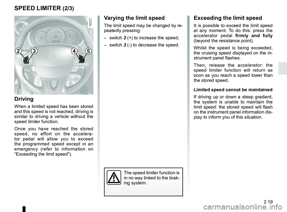
– switch 2 (+) to increase the speed;
– switch 3 (-) to decrease the speed.
2453
Page 123 of 230
2.23
CRUISE CONTROL (3/4)
Exceeding the cruising speed
The cruising speed may be exceeded
at any time by depressing the accelera-
tor pedal. While it is being exceeded,
the cruising speed flashes on the in-
strument panel.
Then, release the accelerator: after a
few seconds, the vehicle will automati-
cally return to its set cruising speed.
Cruising speed cannot be
maintained
When driving down a steep gradient,
the system is unable to maintain the
cruising speed: the stored speed will
flash on the instrument panel informa-
tion display to inform you of this situ-
ation.
Adjusting the cruising speed
The cruising speed may be changed by
pressing the following repeatedly:
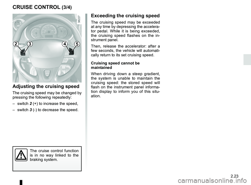
– switch 2 (+) to increase the speed,
– switch 3 (-) to decrease the speed.
The cruise control function
is in no way linked to the
braking system.
2453
Page 127 of 230
2.27
REVERSING CAMERA (1/2)
Operation
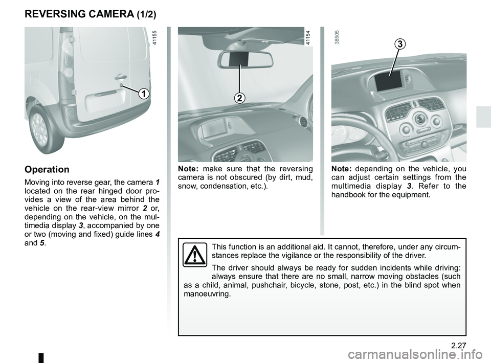
Moving into reverse gear, the camera 1
located on the rear hinged door pro-
vides a view of the area behind the
vehicle on the rear-view mirror 2 or,
depending on the vehicle, on the mul-
timedia display 3, accompanied by one
or two (moving and fixed) guide lines 4
and 5.
Note: make sure that the reversing
camera is not obscured (by dirt, mud,
snow, condensation, etc.). Note: depending on the vehicle, you
can adjust certain settings from the
multimedia display
3. Refer to the
handbook for the equipment.
This function is an additional aid. It cannot, therefore, under any circ\
um-
stances replace the vigilance or the responsibility of the driver.
The driver should always be ready for sudden incidents while driving:
always ensure that there are no small, narrow moving obstacles (such
as a child, animal, pushchair, bicycle, stone, post, etc.) in the blind spot when
manoeuvring.
2
3
1
Page 128 of 230
2.28
REVERSING CAMERA (2/2)
The screen shows a reverse image.
The frames are a representation
projected onto flat ground; this in-
formation must not be taken into
account when superimposed on a
vertical object or an object on the
ground.
Objects which appear on the edge
of the screen may be deformed.
In very bright light (snow, vehicle in
sunshine etc.), the camera vision
may be adversely affected.
If the rear doors are open or poorly
closed, the camera display disap-
pears and, depending on the ve-
hicle, the message “BOOT OPEN”
appears.
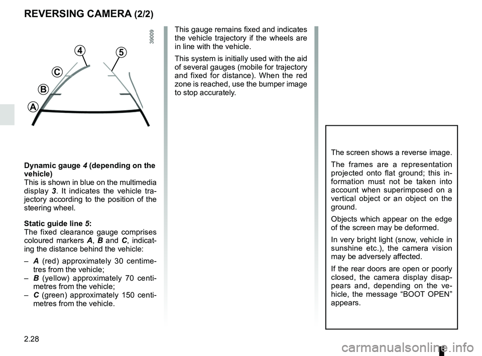
Dynamic gauge 4 (depending on the
vehicle)
This is shown in blue on the multimedia
display 3. It indicates the vehicle tra-
jectory according to the position of the
steering wheel.
Static guide line 5:
The fixed clearance gauge comprises
coloured markers A, B and C , indicat-
ing the distance behind the vehicle:
– A (red) approximately 30 centime-
tres from the vehicle;
– B (yellow) approximately 70 centi-
metres from the vehicle;
– C (green) approximately 150 centi-
metres from the vehicle. This gauge remains fixed and indicates
the vehicle trajectory if the wheels are
in line with the vehicle.
This system is initially used with the aid
of several gauges (mobile for trajectory
and fixed for distance). When the red
zone is reached, use the bumper image
to stop accurately.
4
C
B
A
5
Page 137 of 230
3.9
AIR CONDITIONING, HEATING: programming (2/2)
Activating the function
– With the ignition on, position the con-trol 1 in one of the
ṗ positions;
– turn off the ignition. The “COMFORT” message and the programmed time
are displayed on the instrument
panel for a few seconds;
– wait approximately one minute before charging your vehicle;
– plug in your vehicle to a power supply (refer to the information on “Electric
vehicle: charging” in section 1).
The function switches on during the
hour preceding the programmed time in
order to reach a comfortable tempera-
ture.
Automatically switching off the
function
– About 10 minutes after the pro- grammed time;
– if the charging socket is discon- nected;
– if control 1 is not in one of the
ṗ
positions.
4
5
C
D
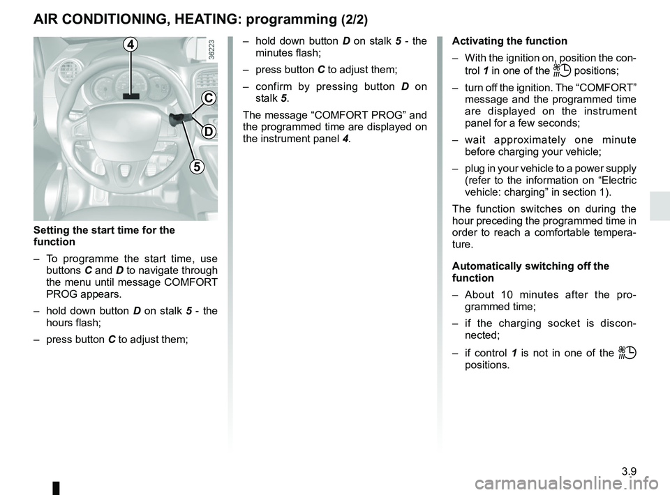
Setting the start time for the
function
– To programme the start time, use buttons C and D to navigate through
the menu until message COMFORT
PROG appears.
– hold down button D on stalk 5 - the
hours flash;
– press button C to adjust them; – hold down button
D on stalk 5 - the
minutes flash;
– press button C to adjust them;
– confirm by pressing button D on
stalk 5.
The message “COMFORT PROG” and
the programmed time are displayed on
the instrument panel 4.
Page 167 of 230
4.13
Glass instrument panel(e.g. instrument panel, clock, exterior
temperature display, radio display, etc.)
Use a soft cloth (or cotton wool).
If this does not clean them properly,
use a soft cloth (or cotton wool) slightly
moistened with soapy water and then
wipe clean with another soft damp cloth
or cotton wool.
Finally, carefully dry off with a soft dry
cloth.
Do not use products containing alco-
hol and/or spray fluids on the area.
Seat belts
These must be kept clean.
Use products selected by our Technical
Department (Approved outlets) or
warm, soapy water and a sponge and
wipe with a dry cloth.
Detergents or dyes must not be used
under any circumstances.
INTERIOR TRIM MAINTENANCE (1/2)
Textiles (seats, door trim, etc)
Vacuum-clean the textiles regularly.
Liquid stain
Use soapy water.
Dab lightly (never rub) with a soft cloth,
rinse and remove the excess.
Solid or pasty stain
Carefully remove the excess solid or
pasty material immediately with a
spatula (working from the edges to the
centre to avoid spreading the stain).
Clean as for a liquid stain.
Special instructions for sweets or
chewing gum
Put an ice cube on the stain to solidify
it, then proceed as for a solid stain.
A well-maintained vehicle will last
longer. It is therefore recommended to
maintain the interior of the vehicle regu-
larly.
A stain should always be dealt with
swiftly.
Whatever type of stain is on the trim,
use
cold (or warm) soapy water with
natural soap.
Detergents (washing-up liquid, pow-
dered products, alcohol-based prod-
ucts) should not be used.
Use a soft cloth.
Rinse and soak up the excess.
For further recommendations for
maintaining the interior, and/or for
any unsatisfactory results, please
see an authorised dealer.
Page 190 of 230

5.22
FUSES (2/2)
Number Allocation
1 Not used
2 Not used
3 Air conditioning, pedestrian
horn
4 heating, traction battery
5 Rear windscreen wiper
6 Horn, diagnostic socket
7 Heated seats, telematic box
8 Traction battery
9 Passenger compartment
ECU
10 Windscreen washer
11 Brake lights
12 Passenger compartment
ECU
13 Electric window, ECO mode
14 Heated rear screen
15 Starter
12
3456
78910
11121314
15161718
19202122
23242526
27
28
29
Allocation of fusesThe presence of certain fuses de-
pends on the vehicle equipment
level.
Number Allocation
16 Brake lights, additional
equipment, ABS, ESP,
luggage compartment light,
courtesy light, rain and light
sensor
17 Radio, navigation system,
display, alarm
18 Additional equipment
19 Heated door mirrors
20 Hazard lights, rear fog lights
21 Central locking of opening
elements
22 Instrument panel
23 Not used
24 Radio, heated seats, brake
lights
25 Front accessories socket
26 Towbar
27 Electric front windows
28 Rear-view mirror control
29 Passenger compartment
motor-driven fan assembly
Page 223 of 230
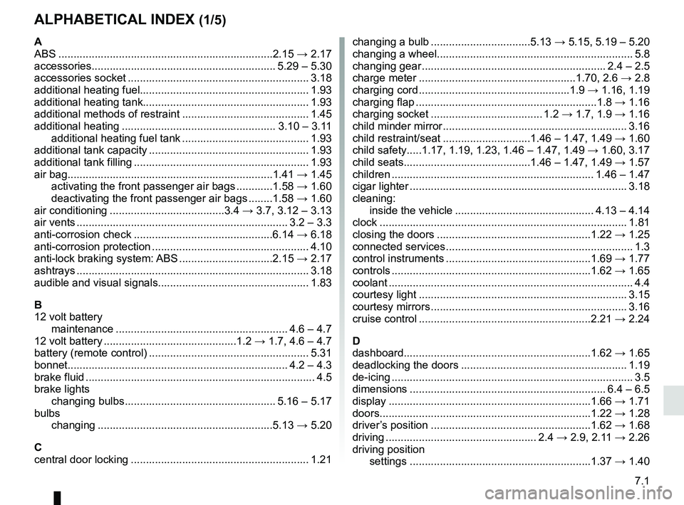
7.1
ALPHABETICAL INDEX (1/5)
A
ABS ....................................................................\
...2.15 → 2.17
accessories............................................................. 5.29 – 5.30
accessories socket ............................................................ 3.18
additional heating fuel........................................................ 1.93
additional heating tank....................................................... 1.93
additional methods of restraint .......................................... 1.45
additional heating ................................................... 3.10 – 3.11 additional heating fuel tank .......................................... 1.93
additional tank capacity ..................................................... 1.93
additional tank filling .......................................................... 1.93
air bag....................................................................1.41 → 1.45
activating the front passenger air bags ............1.58 → 1.60
deactivating the front passenger air bags ........1.58 → 1.60
air conditioning ......................................3.4 → 3.7, 3.12 – 3.13
air vents ...................................................................... 3.2 – 3.3
anti-corrosion check ..............................................6.14 → 6.18
anti-corrosion protection .................................................... 4.10
anti-lock braking system: ABS ...............................2.15 → 2.17
ashtrays ...............................................................\
.............. 3.18
audible and visual signals.................................................. 1.83
B
12 volt battery maintenance ......................................................... 4.6 – 4.7
12 volt battery ............................................1.2 → 1.7, 4.6 – 4.7
battery (remote control) ..................................................... 5.31
bonnet........................................................................\
. 4.2 – 4.3
brake fluid ........................................................................\
.... 4.5
brake lights changing bulbs .................................................. 5.16 – 5.17
bulbs changing ..........................................................5.13 → 5.20
C
central door locking ........................................................... 1.21 changing a bulb .................................5.13
→ 5.15, 5.19 – 5.20
changing a wheel................................................................. 5.8
changing gear ............................................................. 2.4 – 2.5
charge meter ....................................................1.70, 2.6 → 2.8
charging cord ..................................................1.9 → 1.16, 1.19
charging flap ............................................................1.8 → 1.16
charging socket ..................................... 1.2 → 1.7, 1.9 → 1.16
child minder mirror ............................................................. 3.16
child restraint/seat .............................1.46 – 1.47, 1.49 → 1.60
child safety.....1.17, 1.19, 1.23, 1.46 – 1.47, 1.49 → 1.60, 3.17
child seats..........................................1.46 – 1.47, 1.49 → 1.57
children ................................................................... 1.46 – 1.47
cigar lighter ........................................................................\
3.18
cleaning: inside the vehicle .............................................. 4.13 – 4.14
clock ..................................................................\
................ 1.81
closing the doors ...................................................1.22 → 1.25
connected services .............................................................. 1.3
control instruments ................................................1.69 → 1.77
controls ...............................................................\
...1.62 → 1.65
coolant ................................................................\
................. 4.4
courtesy light ..................................................................... 3.15
courtesy mirrors ................................................................. 3.16
cruise control .........................................................2.21 → 2.24
D
dashboard..............................................................1.62 → 1.65
deadlocking the doors ....................................................... 1.19
de-icing ...............................................................\
................. 3.5
dimensions ................................................................. 6.4 – 6.5
display ................................................................\
...1.66 → 1.71
doors......................................................................1.22 → 1.28
driver’s position .....................................................1.62 → 1.68
driving .................................................. 2.4 → 2.9, 2.11 → 2.26
driving position settings ............................................................1.37 →
1.40