fuse RENAULT MASTER 2017 X62 / 2.G Owners Manual
[x] Cancel search | Manufacturer: RENAULT, Model Year: 2017, Model line: MASTER, Model: RENAULT MASTER 2017 X62 / 2.GPages: 286, PDF Size: 6.97 MB
Page 79 of 286
1.73
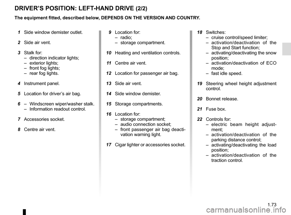
DRIVER’S POSITION: LEFT-HAND DRIVE (2/2)
The equipment fitted, described below, DEPENDS ON THE VERSION AND COUNTRY.
1 Side window demister outlet.
2 Side air vent.
3 Stalk for:
– direction indicator lights;
– exterior lights;
– front fog lights;
– rear fog lights.
4 Instrument panel.
5 Location for driver’s air bag.
6 – Windscreen wiper/washer stalk.
– Information readout control.
7 Accessories socket.
8 Centre air vent.
9 Location for:
– radio;
– storage compartment.
10 Heating and ventilation controls.
11 Centre air vent.
12 Location for passenger air bag.
13 Side air vent.
14 Side window demister.
15 Storage compartments.
16 Location for:
– storage compartment;
– audio connection socket;
– front passenger air bag deacti-vation warning light.
17 Cigar lighter or accessories socket.
18 Switches:
– cruise control/speed limiter;
– activation/deactivation of the Stop and Start function;
– activating/deactivating the snow position;
– activation/deactivation of ECO mode;
– fast idle speed.
19 Steering wheel height adjustment
control.
20 Bonnet release.
21 Fuse box.
22 Controls for:
– electric beam height adjust-ment;
– activation/deactivation of the parking distance control;
– activating/deactivating the load position;
– activation/deactivation of the traction control.
Page 81 of 286
1.75
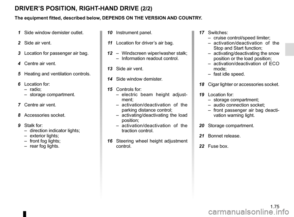
DRIVER’S POSITION, RIGHT-HAND DRIVE (2/2)
The equipment fitted, described below, DEPENDS ON THE VERSION AND COUNTRY.
1 Side window demister outlet.
2 Side air vent.
3 Location for passenger air bag.
4 Centre air vent.
5 Heating and ventilation controls.
6 Location for:
– radio;
– storage compartment.
7 Centre air vent.
8 Accessories socket.
9 Stalk for:
– direction indicator lights;
– exterior lights;
– front fog lights;
– rear fog lights.
10 Instrument panel.
11 Location for driver’s air bag.
12 – Windscreen wiper/washer stalk;
– Information readout control.
13 Side air vent.
14 Side window demister.
15 Controls for:
– electric beam height adjust-ment;
– activation/deactivation of the parking distance control;
– activating/deactivating the load position;
– activation/deactivation of the traction control.
16 Steering wheel height adjustment
control.
17 Switches:
– cruise control/speed limiter;
– activation/deactivation of the Stop and Start function;
– activating/deactivating the snow position or the load position;
– activation/deactivation of ECO mode;
– fast idle speed.
18 Cigar lighter or accessories socket.
19 Location for:
– storage compartment;
– audio connection socket;
– front passenger air bag deacti-vation warning light.
20 Storage compartment.
21 Bonnet release.
22 Fuse box.
Page 175 of 286
3.13
Operating faults
As a general rule, contact your ap-
proved dealer in the event of an oper-
ating fault.
– Reduction in de-icing, demisting or air conditioning performance.
This may be caused by the passen-
ger compartment filter cartridge be-
coming clogged.
– No cold air is being produced .
Check that the controls are set cor-
rectly and that the fuses are sound.
Otherwise, switch off the system.
Presence of water under the
vehicle
After prolonged use of the air condi-
tioning system, it is normal for water
to be present under the vehicle. This is
caused by condensation.
AIR CONDITIONING: information and operating instructions (1/2)
Do not open the refriger-
ant fluid circuit. The fluid
may damage eyes or skin.
Fuel consumption
You will normally notice an increase in
fuel consumption (especially in town)
when the air conditioning is operating.
For vehicles fitted with air conditioning
with no automatic mode, switch off the
system when it is not required.
Advice for reducing consumption
and helping to preserve the environ-
ment
Drive with the air vents open and the
windows closed.
If the vehicle has been parked in the
sun, open the doors for a few moments
to let the hot air escape before starting
the engine.
Advice on use
In some situations (air conditioning off,
air recirculation activated, ventilation
speed at zero or low etc.), you may
notice that condensation starts to form
on the windows and windscreen.
If there is condensation, use the “Clear
View” function to remove it, then use
the air conditioning in automatic mode
to stop it forming again.
Maintenance
Refer to the Maintenance Document
for your vehicle for the inspection fre-
quency.
Do not add anything to the
vehicle’s ventilation circuit
(for example, to remove
bad odours).
There is a risk of damage or of
fire.
Page 211 of 286
5.1
Section 5: Practical advice
Puncture . . . . . . . . . . . . . . . . . . . . . . . . . . . . . . . . . . . .\
. . . . . . . . . . . . . . . . . . . . . . . . . . . . . . . . . . 5.2
Emergency spare wheel . . . . . . . . . . . . . . . . . . . . . . . . . . . . . . . . . . . .\
. . . . . . . . . . . . . . . . . . . . . . 5.2
Tool kit . . . . . . . . . . . . . . . . . . . . . . . . . . . . . . . . . . . . \
. . . . . . . . . . . . . . . . . . . . . . . . . . . . . . . . . . . . 5.4
Tyre inflation kit . . . . . . . . . . . . . . . . . . . . . . . . . . . . . . . . . . . .\
. . . . . . . . . . . . . . . . . . . . . . . . . . . . . 5.5
Wheel trims . . . . . . . . . . . . . . . . . . . . . . . . . . . . . . \
. . . . . . . . . . . . . . . . . . . . . . . . . . . . . . . . . . . . . . 5.11
Changing a wheel: hydraulic jack . . . . . . . . . . . . . . . . . . . . . . . . . . . . . . . . . . . .\
. . . . . . . . . . . . . . . 5.13
Changing a wheel: jack . . . . . . . . . . . . . . . . . . . . . . . . . . . . . . . . . . . . \
. . . . . . . . . . . . . . . . . . . . . . . 5.16
Tyres . . . . . . . . . . . . . . . . . . . . . . . . . . . . . . . . . . . .\
. . . . . . . . . . . . . . . . . . . . . . . . . . . . . . . . . . . . . 5.18
Headlights (changing bulbs) . . . . . . . . . . . . . . . . . . . . . . . . . . . . . . . . . . . .\
. . . . . . . . . . . . . . . . . . . 5.21front fog lights . . . . . . . . . . . . . . . . . . . . . . . . . . . . . . . . . . . . \
. . . . . . . . . . . . . . . . . . . . . . . . . 5.23
Side lights . . . . . . . . . . . . . . . . . . . . . . . . . . . . . . . . . . . . \
. . . . . . . . . . . . . . . . . . . . . . . . . . . . 5.24
Rear lights . . . . . . . . . . . . . . . . . . . . . . . . . . . . . . . . . . . .\
. . . . . . . . . . . . . . . . . . . . . . . . . . . 5.25
Interior lighting . . . . . . . . . . . . . . . . . . . . . . . . . . . . . . . . . . . .\
. . . . . . . . . . . . . . . . . . . . . . . . 5.27
Fuses . . . . . . . . . . . . . . . . . . . . . . . . . . . . . . . . . . . . \
. . . . . . . . . . . . . . . . . . . . . . . . . . . . . . . . . . . . . 5.28
Battery: troubleshooting. . . . . . . . . . . . . . . . . . . . . . . . . . . . . . . . . . . . \
. . . . . . . . . . . . . . . . . . . . . . . 5.33
Key, radio frequency remote control: battery . . . . . . . . . . . . . . . . . . . . . . . . . . . . . . . . . . . . \
. . . . . . . 5.35
Hands-free access transmitter/receiver: battery . . . . . . . . . . . . . . . . . . . . . . . . . . . . . . . . . . . .\
. . . . 5.36
Replacing wiper blades . . . . . . . . . . . . . . . . . . . . . . . . . . . . . . . . . . . . \
. . . . . . . . . . . . . . . . . . . . . . . 5.37
Towing . . . . . . . . . . . . . . . . . . . . . . . . . . . . . . . . . . . . \
. . . . . . . . . . . . . . . . . . . . . . . . . . . . . . . . . . . . 5.38
Fitting a radio . . . . . . . . . . . . . . . . . . . . . . . . . . . . . . . . . . . . \
. . . . . . . . . . . . . . . . . . . . . . . . . . . . . . . 5.40
Accessories . . . . . . . . . . . . . . . . . . . . . . . . . . . . . . . . . . . . \
. . . . . . . . . . . . . . . . . . . . . . . . . . . . . . . . 5.41
Operating faults . . . . . . . . . . . . . . . . . . . . . . . . . . . . . . . . . . . . \
. . . . . . . . . . . . . . . . . . . . . . . . . . . . . 5.42
Page 231 of 286
5.21
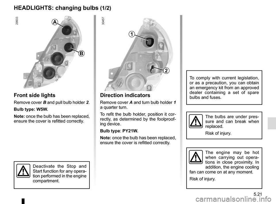
Direction indicators
Remove cover A and turn bulb holder 1
a quarter turn.
To refit the bulb holder, position it cor-
rectly, as determined by the foolproof-
ing device.
Bulb type: PY21W.
Note: once the bulb has been replaced,
ensure the cover is refitted correctly.
HEADLIGHTS: changing bulbs (1/2)
Front side lights
Remove cover B and pull bulb holder 2.
Bulb type: W5W.
Note: once the bulb has been replaced,
ensure the cover is refitted correctly.
The bulbs are under pres-
sure and can break when
replaced.
Risk of injury.
To comply with current legislation,
or as a precaution, you can obtain
an emergency kit from an approved
dealer containing a set of spare
bulbs and fuses.
B
A
2
1
The engine may be hot
when carrying out opera-
tions in close proximity. In
addition, the engine cooling
fan can come on at any moment.
Risk of injury.
Deactivate the Stop and
Start function for any opera-
tion performed in the engine
compartment.
Page 232 of 286
5.22
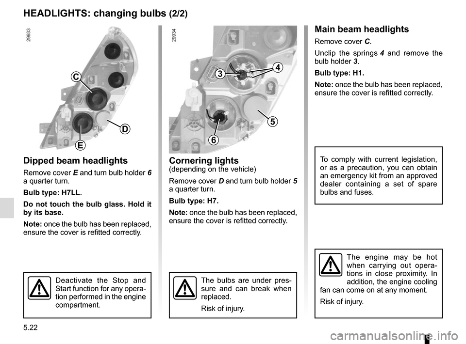
Dipped beam headlights
Remove cover E and turn bulb holder 6
a quarter turn.
Bulb type: H7LL.
Do not touch the bulb glass. Hold it
by its base.
Note: once the bulb has been replaced,
ensure the cover is refitted correctly.
Main beam headlights
Remove cover C.
Unclip the springs 4 and remove the
bulb holder 3.
Bulb type: H1.
Note: once the bulb has been replaced,
ensure the cover is refitted correctly.
The bulbs are under pres-
sure and can break when
replaced.
Risk of injury.
To comply with current legislation,
or as a precaution, you can obtain
an emergency kit from an approved
dealer containing a set of spare
bulbs and fuses.
HEADLIGHTS: changing bulbs (2/2)
Cornering lights
(depending on the vehicle)
Remove cover D and turn bulb holder 5
a quarter turn.
Bulb type: H7.
Note: once the bulb has been replaced,
ensure the cover is refitted correctly.
C
D
E
3
5
6
4
The engine may be hot
when carrying out opera-
tions in close proximity. In
addition, the engine cooling
fan can come on at any moment.
Risk of injury.
Deactivate the Stop and
Start function for any opera-
tion performed in the engine
compartment.
Page 234 of 286
5.24
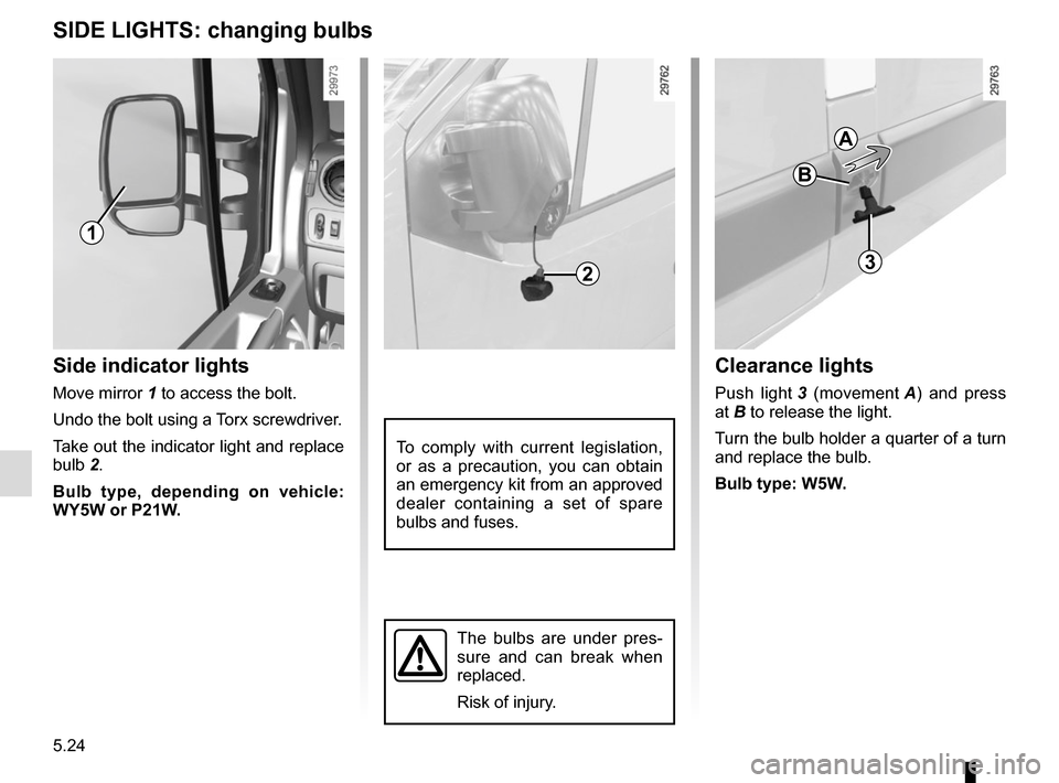
SIDE LIGHTS: changing bulbs
Side indicator lights
Move mirror 1 to access the bolt.
Undo the bolt using a Torx screwdriver.
Take out the indicator light and replace
bulb 2.Bulb type, depending on vehicle:
WY5W or P21W.
1
23
Clearance lights
Push light 3 (movement A) and press
at B to release the light.
Turn the bulb holder a quarter of a turn
and replace the bulb.
Bulb type: W5W.
To comply with current legislation,
or as a precaution, you can obtain
an emergency kit from an approved
dealer containing a set of spare
bulbs and fuses.
The bulbs are under pres-
sure and can break when
replaced.
Risk of injury.
B
A
Page 237 of 286
5.27
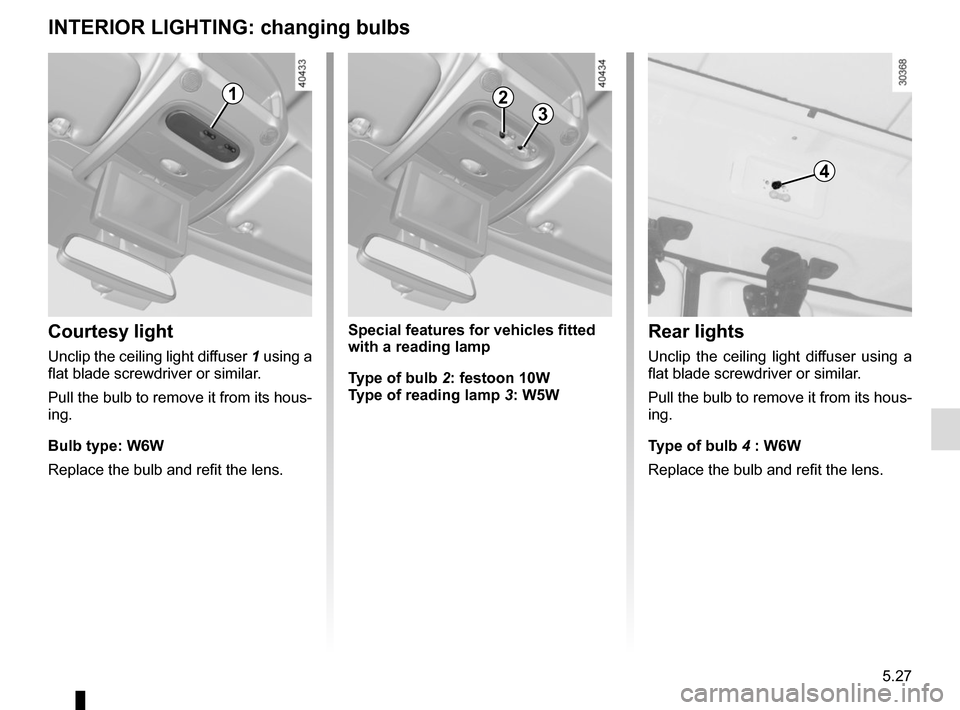
INTERIOR LIGHTING: changing bulbs
Courtesy light
Unclip the ceiling light diffuser 1 using a
flat blade screwdriver or similar.
Pull the bulb to remove it from its hous-
ing.
Bulb type: W6W
Replace the bulb and refit the lens.
Rear lights
Unclip the ceiling light diffuser using a
flat blade screwdriver or similar.
Pull the bulb to remove it from its hous-
ing.
Type of bulb 4 : W6W
Replace the bulb and refit the lens.
1
4
Special features for vehicles fitted
with a reading lamp
Type of bulb 2: festoon 10W
Type of reading lamp 3: W5W
23
Page 238 of 286
5.28
FUSES (1/5)
1
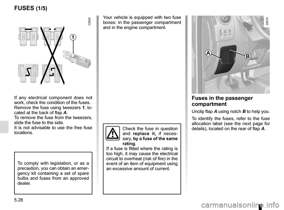
If any electrical component does not
work, check the condition of the fuses.
Remove the fuse using tweezers 1, lo-
cated at the back of flap A.
To remove the fuse from the tweezers,
slide the fuse to the side.
It is not advisable to use the free fuse
locations.
To comply with legislation, or as a
precaution, you can obtain an emer-
gency kit containing a set of spare
bulbs and fuses from an approved
dealer.
Your vehicle is equipped with two fuse
boxes: in the passenger compartment
and in the engine compartment.
A
Fuses in the passenger
compartment
Unclip flap A using notch B to help you.
To identify the fuses, refer to the fuse
allocation label (see the next page for
details), located on the rear of flap A.
B
Check the fuse in question
and replace it, if neces-
sary, by a fuse of the same
rating.
If a fuse is fitted where the rating is
too high, it may cause the electrical
circuit to overheat (risk of fire) in the
event of an item of equipment using
an excessive amount of current.
Page 239 of 286
5.29
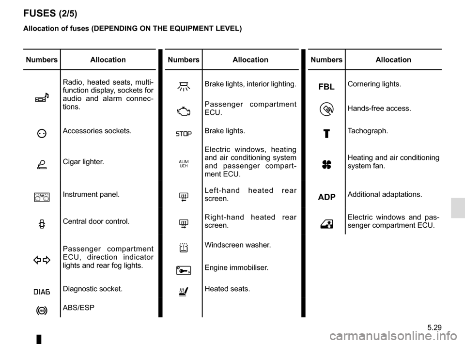
FUSES (2/5)
Allocation of fuses (DEPENDING ON THE EQUIPMENT LEVEL)
Numbers AllocationNumbers Allocation Numbers Allocation
î
Radio, heated seats, multi-
function display, sockets for
audio and alarm connec-
tions.ZBrake lights, interior lighting.Cornering lights.
ÄPassenger compartment
ECU.Hands-free access.
ëAccessories sockets.ßBrake lights.£Tachograph.
ÆCigar lighter.‚
Electric windows, heating
and air conditioning system
and passenger compart-
ment ECU.
yHeating and air conditioning
system fan.
aInstrument panel.8Left-hand heated rear
screen.Additional adaptations.
NCentral door control.7Right-hand heated rear
screen.hElectric windows and pas-
senger compartment ECU.
D
Passenger compartment
ECU, direction indicator
lights and rear fog lights.lWindscreen washer.
0Engine immobiliser.
ÎDiagnostic socket.ñHeated seats.
nABS/ESP