RENAULT MASTER 2017 X62 / 2.G Owners Manual
Manufacturer: RENAULT, Model Year: 2017, Model line: MASTER, Model: RENAULT MASTER 2017 X62 / 2.GPages: 286, PDF Size: 6.97 MB
Page 241 of 286
5.31
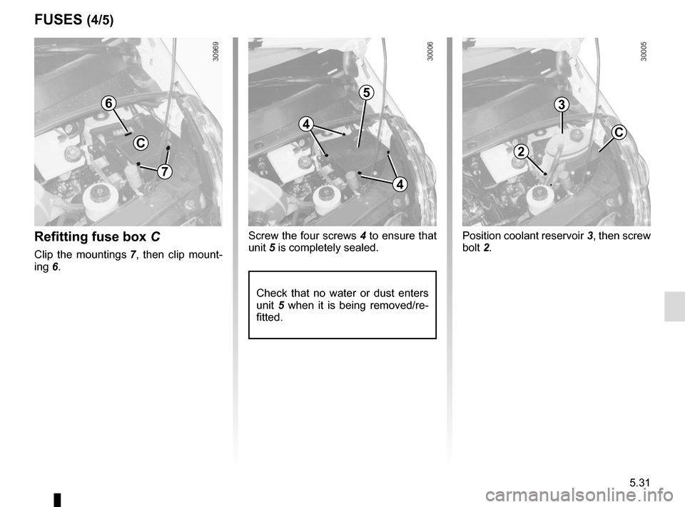
Position coolant reservoir 3, then screw
bolt 2.Refitting fuse box C
Clip the mountings 7, then clip mount-
ing 6. Screw the four screws 4 to ensure that
unit 5 is completely sealed.
2
3
C4
4
5
7
6
FUSES (4/5)
5
Check that no water or dust enters
unit 5 when it is being removed/re-
fitted.
C
Page 242 of 286
5.32
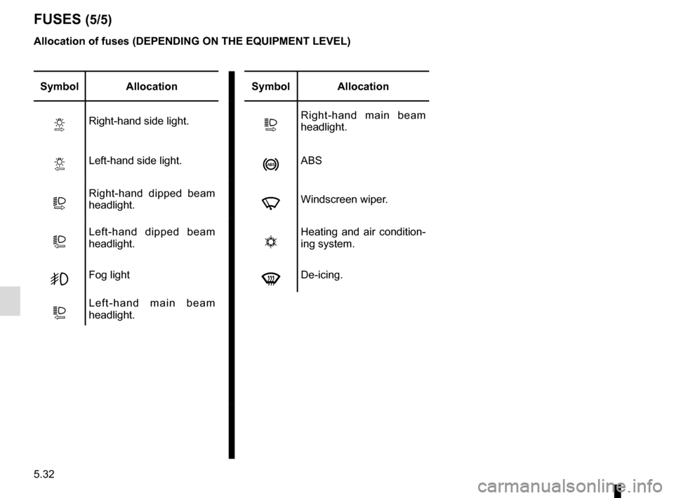
FUSES (5/5)
Symbol AllocationSymbol Allocation
VRight-hand side light.PRight-hand main beam
headlight.
YLeft-hand side light.nABS
TRight-hand dipped beam
headlight.fWindscreen wiper.
LLeft-hand dipped beam
headlight.tHeating and air condition-
ing system.
GFog lightdDe-icing.
QLeft-hand main beam
headlight.
Allocation of fuses (DEPENDING ON THE EQUIPMENT LEVEL)
Page 243 of 286
5.33
Connecting a battery charger
The battery charger must be com-
patible with a battery with nominal
voltage of 12 volts.
Do not disconnect the battery when the
engine is running. Follow the instruc-
tions given by the manufacturer of
the battery charger you are using.
When many accessories are fitted to
the vehicle, have them connected to
the + after ignition feed .
BATTERY: troubleshooting (1/2)
To avoid all risk of sparks:
– Ensure that any consumers (cour-
tesy lights, etc.) are switched off
before disconnecting or reconnect-
ing the battery;
– when charging, stop the charger before connecting or disconnecting
the battery;
– to avoid creating a short circuit be- tween the terminals, do not place
metal objects on the battery;
– always wait at least one minute after the engine has been switched off
before disconnecting a battery;
– make sure that you reconnect the battery terminals after refitting.
Special procedures may be
required to charge some
batteries. Contact your ap-
proved dealer.
Avoid all risk of sparks which may
cause an immediate explosion, and
charge the battery in a well-venti-
lated area. Risk of serious injury.
Handle the battery with care
as it contains sulphuric acid,
which must not come into
contact with eyes or skin. If
it does, wash the affected area with
plenty of cold water. If necessary,
consult a doctor.
Ensure that naked flames, red hot
objects and sparks do not come into
contact with the battery as there is a
risk of explosion.
The engine may be hot when car-
rying out operations in close prox-
imity. In addition, the engine cooling
fan can come on at any moment.
Risk of injury.
Page 244 of 286
5.34
BATTERY: troubleshooting (2/2)
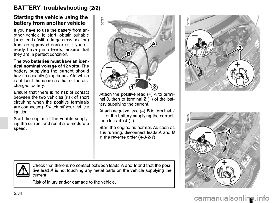
Attach the positive lead (+) A to termi-
nal 3, then to terminal 2 (+) of the bat-
tery supplying the current.
Attach negative lead (–) B to terminal 1
(–) of the battery supplying the current,
then to earth 4 (–).
Start the engine as normal. As soon as
it is running, disconnect leads A and B
in the reverse order ( 4-3-2-1).
Starting the vehicle using the
battery from another vehicle
If you have to use the battery from an-
other vehicle to start, obtain suitable
jump leads (with a large cross section)
from an approved dealer or, if you al-
ready have jump leads, ensure that
they are in perfect condition.
The two batteries must have an iden-
tical nominal voltage of 12 volts. The
battery supplying the current should
have a capacity (amp-hours, Ah) which
is at least the same as that of the dis-
charged battery.
Ensure that there is no risk of contact
between the two vehicles (risk of short
circuiting when the positive terminals
are connected). Switch off your vehicle
ignition.
Start the engine of the vehicle supply-
ing the current and run it at a moderate
speed.
A
B
21
Check that there is no contact between leads A and B and that the posi-
tive lead A is not touching any metal parts on the vehicle supplying the
current.
Risk of injury and/or damage to the vehicle.
3
4
4
3
Page 245 of 286
5.35
RADIO FREQUENCY REMOTE CONTROL: battery
Do not dispose of your used
batteries in the countryside.
Give them to an organisa-
tion that collects and recy-
cles used batteries.
1
Replacing the remote control
battery
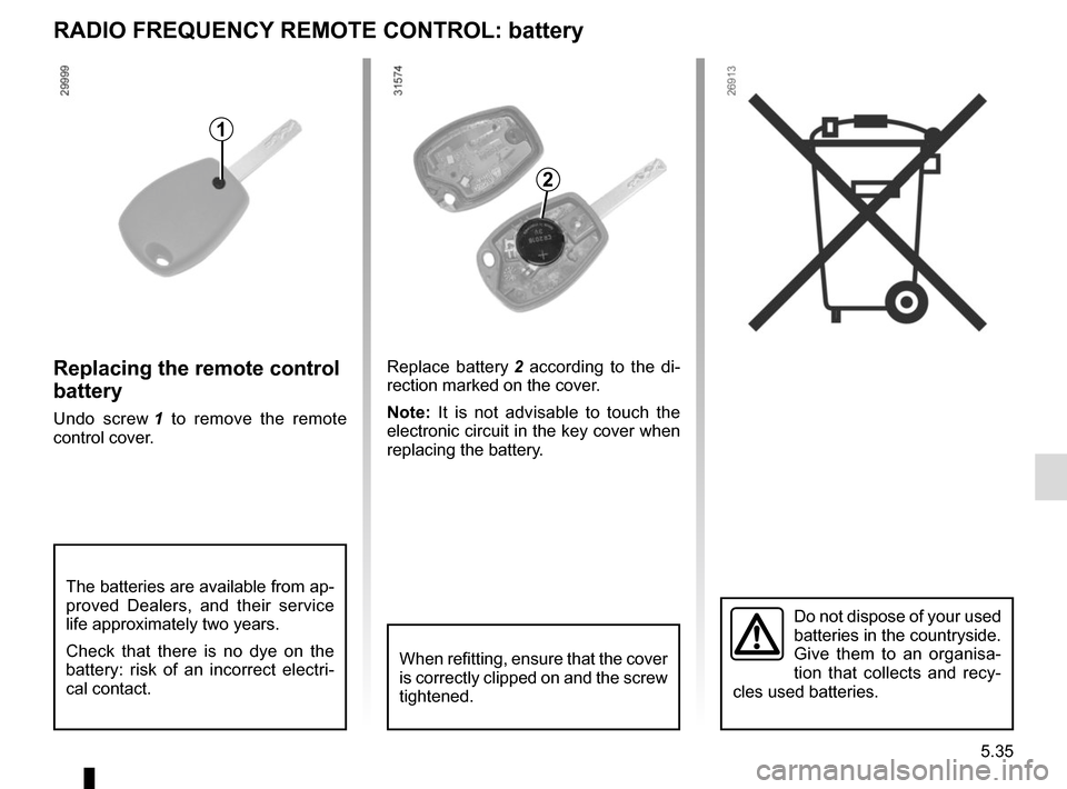
Undo screw 1 to remove the remote
control cover. Replace battery
2 according to the di-
rection marked on the cover.
Note: It is not advisable to touch the
electronic circuit in the key cover when
replacing the battery.
When refitting, ensure that the cover
is correctly clipped on and the screw
tightened.
The batteries are available from ap-
proved Dealers, and their service
life approximately two years.
Check that there is no dye on the
battery: risk of an incorrect electri-
cal contact.
2
Page 246 of 286
5.36
HANDS-FREE ACCESS TRANSMITTER/RECEIVER: battery
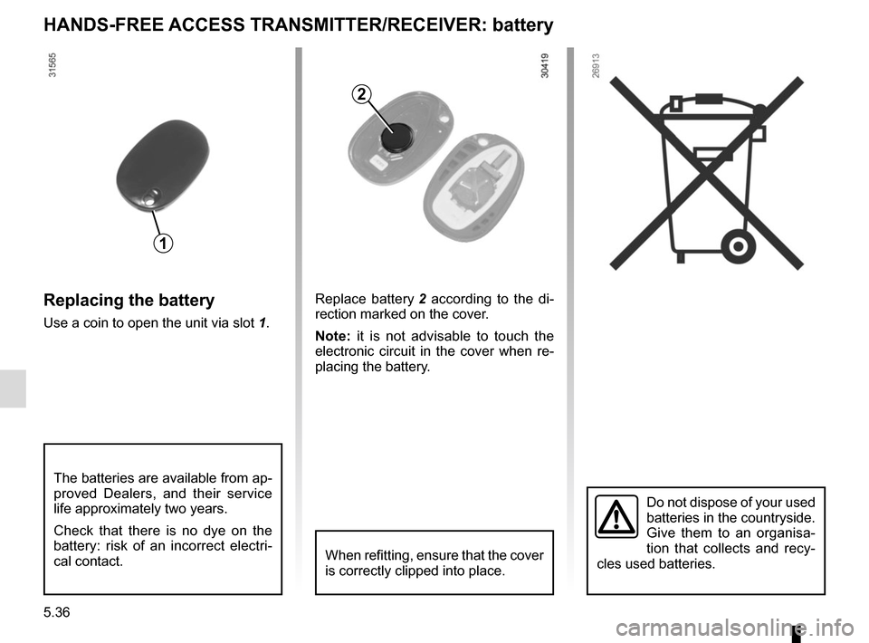
Replacing the battery
Use a coin to open the unit via slot 1.
Do not dispose of your used
batteries in the countryside.
Give them to an organisa-
tion that collects and recy-
cles used batteries.
1
2
Replace battery 2 according to the di-
rection marked on the cover.
Note: it is not advisable to touch the
electronic circuit in the cover when re-
placing the battery.
When refitting, ensure that the cover
is correctly clipped into place.
The batteries are available from ap-
proved Dealers, and their service
life approximately two years.
Check that there is no dye on the
battery: risk of an incorrect electri-
cal contact.
Page 247 of 286
5.37
WIPER BLADES
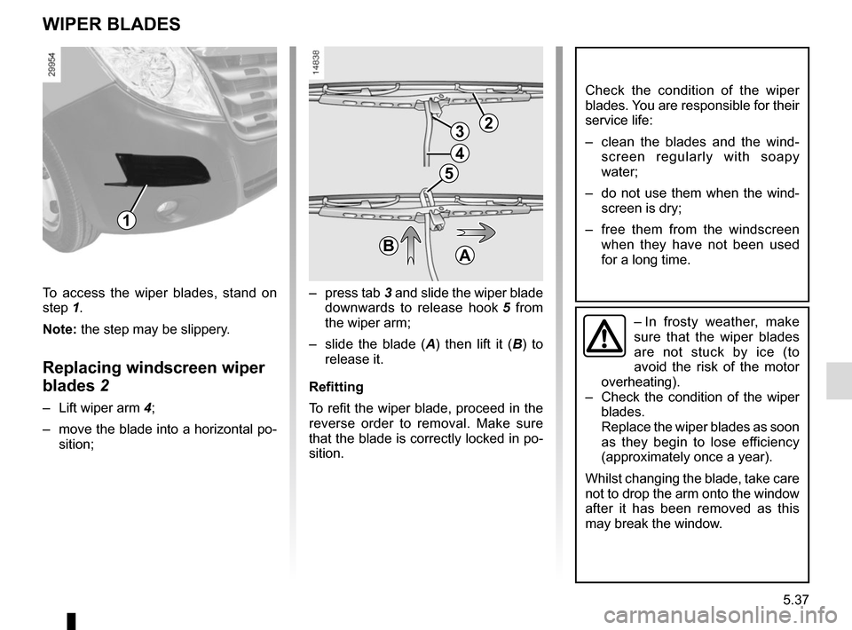
– press tab 3 and slide the wiper blade
downwards to release hook 5 from
the wiper arm;
– slide the blade ( A) then lift it ( B) to
release it.
Refitting
To refit the wiper blade, proceed in the
reverse order to removal. Make sure
that the blade is correctly locked in po-
sition.
Check the condition of the wiper
blades. You are responsible for their
service life:
– clean the blades and the wind- screen regularly with soapy
water;
– do not use them when the wind- screen is dry;
– free them from the windscreen when they have not been used
for a long time.
– In frosty weather, make
sure that the wiper blades
are not stuck by ice (to
avoid the risk of the motor
overheating).
– Check the condition of the wiper
blades.
Replace the wiper blades as soon
as they begin to lose efficiency
(approximately once a year).
Whilst changing the blade, take care
not to drop the arm onto the window
after it has been removed as this
may break the window.
23
4
5
BA
To access the wiper blades, stand on
step 1. Note: the step may be slippery.
Replacing windscreen wiper
blades 2
– Lift wiper arm 4;
– move the blade into a horizontal po- sition;
1
Page 248 of 286
5.38
TOWING: breakdown (1/2)
The steering wheel must be un-
locked and the ignition key must be
in position M (ignition on) to provide
brake lights and hazard warning
lights on the towed vehicle. At night
the vehicle must have its lights on.
Unhitch the trailer, etc., if one is
being towed.
You must observe the towing regu-
lations which apply in the country in
which you are driving: do not exceed
the towing weight for your vehicle.
Contact an approved dealer.
– Use a rigid towing bar.
If a rope or cable is used
(where the law allows this),
the vehicle being towed
must be able to brake.
– A vehicle must not be towed if it is not fit to be driven.
– Avoid accelerating or braking suddenly when towing, as this
may result in damage being
caused to the vehicle.
– When towing a vehicle, it is ad- visable not to exceed 15 mph
(25 km/h).
When the engine is
stopped, steering and brak-
ing assistance are not op-
erational.
Do not remove the key from
the ignition when the vehi-
cle is being towed.
Towing a vehicle with a
sequential gearbox
If the gearbox is stuck in a gear:
– switch on the ignition;
– select neutral with the brake pedal depressed;
– check that the gearbox is in neutral (by pushing the vehicle for example).
If you cannot find neutral you must tow
the vehicle with the front wheels raised.
The vehicle should always be towed
with the ignition switched off.
Page 249 of 286
5.39
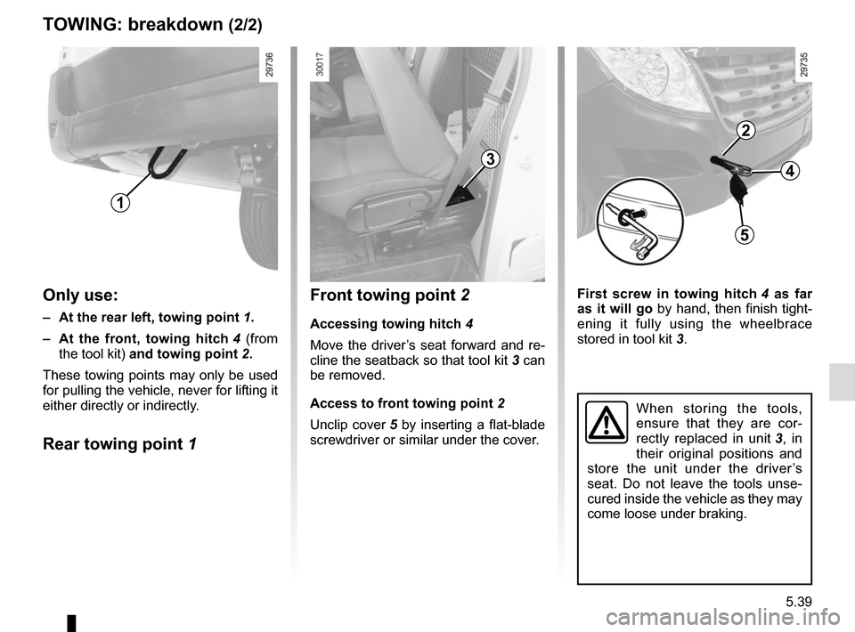
First screw in towing hitch 4 as far
as it will go by hand, then finish tight-
ening it fully using the wheelbrace
stored in tool kit 3.
TOWING: breakdown (2/2)
When storing the tools,
ensure that they are cor-
rectly replaced in unit 3, in
their original positions and
store the unit under the driver’s
seat. Do not leave the tools unse-
cured inside the vehicle as they may
come loose under braking.
Front towing point 2
Accessing towing hitch 4
Move the driver’s seat forward and re-
cline the seatback so that tool kit 3 can
be removed.
Access to front towing point 2
Unclip cover 5 by inserting a flat-blade
screwdriver or similar under the cover.
3
2
5
4
1
Only use:
– At the rear left, towing point 1.
– At the front, towing hitch 4 (from
the tool kit) and towing point 2.
These towing points may only be used
for pulling the vehicle, never for lifting it
either directly or indirectly.
Rear towing point 1
Page 250 of 286
5.40
FITTING THE RADIO
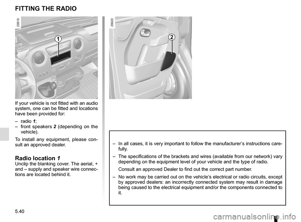
If your vehicle is not fitted with an audio
system, one can be fitted and locations
have been provided for:
– radio 1;
– front speakers 2 (depending on the
vehicle).
To install any equipment, please con-
sult an approved dealer.
Radio location 1Unclip the blanking cover. The aerial, +
and – supply and speaker wire connec-
tions are located behind it.
– In all cases, it is very important to follow the manufacturer’s instructions care-
fully.
– The specifications of the brackets and wires (available from our networ\
k) vary depending on the equipment level of your vehicle and the type of radio.
Consult an approved Dealer to find out the correct part number.
– No work may be carried out on the vehicle’s electrical or radio circuits, except by approved dealers: an incorrectly connected system may result in damag\
e
being caused to the electrical equipment and/or the components connected\
to
it.
12