traction control RENAULT MASTER 2018 Owners Manual
[x] Cancel search | Manufacturer: RENAULT, Model Year: 2018, Model line: MASTER, Model: RENAULT MASTER 2018Pages: 290, PDF Size: 7.1 MB
Page 81 of 290
1.75
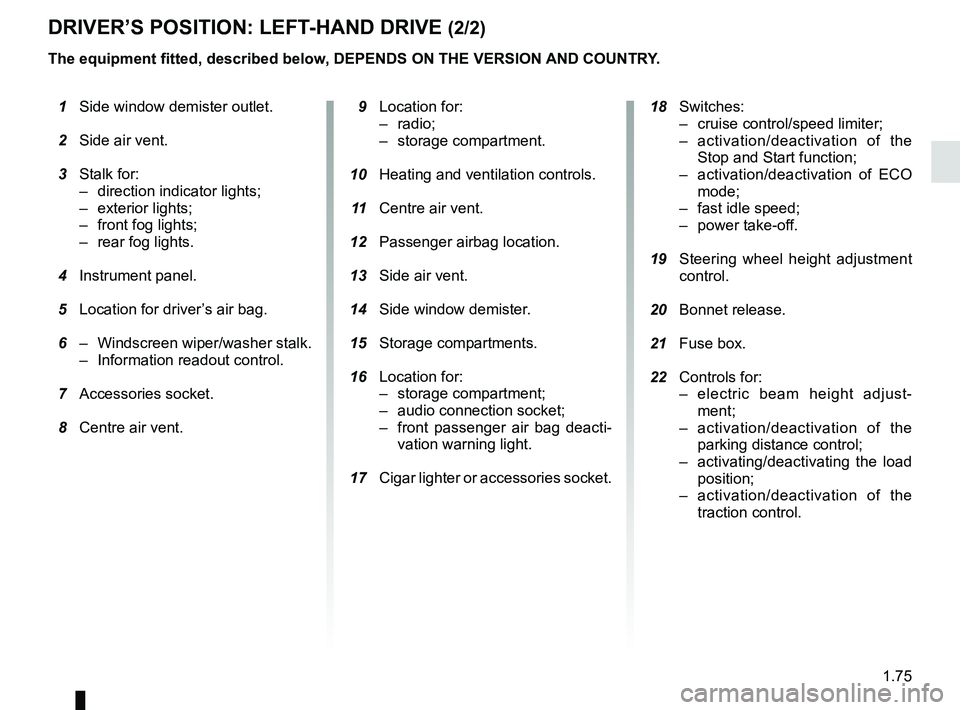
DRIVER’S POSITION: LEFT-HAND DRIVE (2/2)
The equipment fitted, described below, DEPENDS ON THE VERSION AND COUNTRY.
1 Side window demister outlet.
2 Side air vent.
3 Stalk for:
– direction indicator lights;
– exterior lights;
– front fog lights;
– rear fog lights.
4 Instrument panel.
5 Location for driver’s air bag.
6 – Windscreen wiper/washer stalk.
– Information readout control.
7 Accessories socket.
8 Centre air vent.
9 Location for:
– radio;
– storage compartment.
10 Heating and ventilation controls.
11 Centre air vent.
12 Passenger airbag location.
13 Side air vent.
14 Side window demister.
15 Storage compartments.
16 Location for:
– storage compartment;
– audio connection socket;
– front passenger air bag deacti-vation warning light.
17 Cigar lighter or accessories socket.
18 Switches:
– cruise control/speed limiter;
– activation/deactivation of the Stop and Start function;
– activation/deactivation of ECO mode;
– fast idle speed;
– power take-off.
19 Steering wheel height adjustment
control.
20 Bonnet release.
21 Fuse box.
22 Controls for:
– electric beam height adjust-ment;
– activation/deactivation of the parking distance control;
– activating/deactivating the load position;
– activation/deactivation of the traction control.
Page 83 of 290
1.77
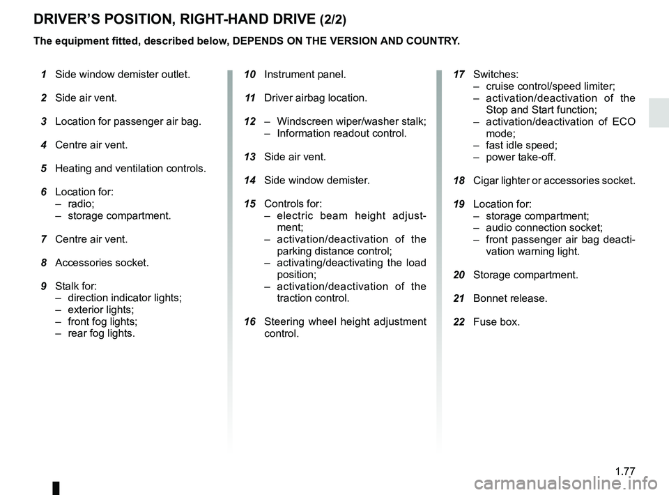
DRIVER’S POSITION, RIGHT-HAND DRIVE (2/2)
The equipment fitted, described below, DEPENDS ON THE VERSION AND COUNTRY.
1 Side window demister outlet.
2 Side air vent.
3 Location for passenger air bag.
4 Centre air vent.
5 Heating and ventilation controls.
6 Location for:
– radio;
– storage compartment.
7 Centre air vent.
8 Accessories socket.
9 Stalk for:
– direction indicator lights;
– exterior lights;
– front fog lights;
– rear fog lights.
10 Instrument panel.
11 Driver airbag location.
12 – Windscreen wiper/washer stalk;
– Information readout control.
13 Side air vent.
14 Side window demister.
15 Controls for:
– electric beam height adjust-ment;
– activation/deactivation of the parking distance control;
– activating/deactivating the load position;
– activation/deactivation of the traction control.
16 Steering wheel height adjustment
control.
17 Switches:
– cruise control/speed limiter;
– activation/deactivation of the Stop and Start function;
– activation/deactivation of ECO mode;
– fast idle speed;
– power take-off.
18 Cigar lighter or accessories socket.
19 Location for:
– storage compartment;
– audio connection socket;
– front passenger air bag deacti-vation warning light.
20 Storage compartment.
21 Bonnet release.
22 Fuse box.
Page 86 of 290
1.80
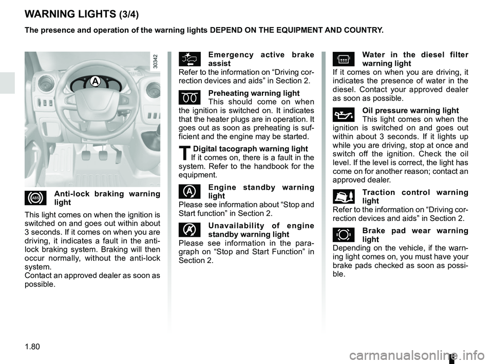
WARNING LIGHTS (3/4)
The presence and operation of the warning lights DEPEND ON THE EQUIPMENT\
AND COUNTRY.
xAnti-lock braking warning
light
This light comes on when the ignition is
switched on and goes out within about
3 seconds. If it comes on when you are
driving, it indicates a fault in the anti-
lock braking system. Braking will then
occur normally, without the anti-lock
system.
Contact an approved dealer as soon as
possible.
^Water in the diesel filter
warning light
If it comes on when you are driving, it
indicates the presence of water in the
diesel. Contact your approved dealer
as soon as possible.
ÀOil pressure warning light
This light comes on when the
ignition is switched on and goes out
within about 3 seconds. If it lights up
while you are driving, stop at once and
switch off the ignition. Check the oil
level. If the level is correct, the light has
come on for another reason; contact an
approved dealer.
Traction control warning
light
Refer to the information on “Driving cor-
rection devices and aids” in Section 2.
zBrake pad wear warning
light
Depending on the vehicle, if the warn-
ing light comes on, you must have your
brake pads checked as soon as possi-
ble.
Emergency active brake
assist
Refer to the information on “Driving cor-
rection devices and aids” in Section 2.
ÉPreheating warning light
This should come on when
the ignition is switched on. It indicates
that the heater plugs are in operation. It
goes out as soon as preheating is suf-
ficient and the engine may be started.
T Digital tacograph warning light
If it comes on, there is a fault in the
system. Refer to the handbook for the
equipment.
Engine standby warning
light
Please see information about “Stop and
Start function” in Section 2.
\fUnavailability of engine
standby warning light
Please see information in the para-
graph on “Stop and Start Function” in
Section 2.
A
Page 96 of 290
1.90
TRIP COMPUTER: information messages
Examples of messagesInterpretation of messages
TRACTION CONTROL OFF Indicates that you have deactivated the traction control function.
BATTERY MODE: ECONOMY Indicates that vehicle accessories have been switched off to preserve the battery.
OIL LEVEL CORRECT Indicates that the oil level is correct when the ignition is switched on\
.
These can help in the vehicle starting phase, or give information about \
a selection or a driving status.
Examples of information messages are given in the following pages.
Page 97 of 290
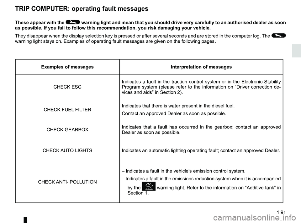
1.91
These appear with the © warning light and mean that you should drive very carefully to an author\
ised dealer as soon
as possible. If you fail to follow this recommendation, you risk damagin\
g your vehicle.
They disappear when the display selection key is pressed or after severa\
l seconds and are stored in the computer log. The
©
warning light stays on. Examples of operating fault messages are given o\
n the following pages .
TRIP COMPUTER: operating fault messages
Examples of messagesInterpretation of messages
CHECK ESC Indicates a fault in the traction control system or in the Electronic St\
ability
Program system (please refer to the information on “Driver correctio\
n de-
vices and aids” in Section 2).
CHECK FUEL FILTER Indicates that there is water present in the diesel fuel.
Contact an approved Dealer as soon as possible.
CHECK GEARBOX Indicates that a fault has occurred in the gearbox; contact an approved
Dealer as soon as possible.
CHECK AUTO LIGHTS Indicates an automatic lighting operating fault; contact an approved Dea\
ler.
CHECK ANTI- POLLUTION – Indicates a fault in the vehicle’s emission control system.
– Indicates a fault in the emissions reduction system when it is acco\
mpanied
by the
warning light. Refer to the information on “Additive tank” in
Section 1.
Page 133 of 290
2.17
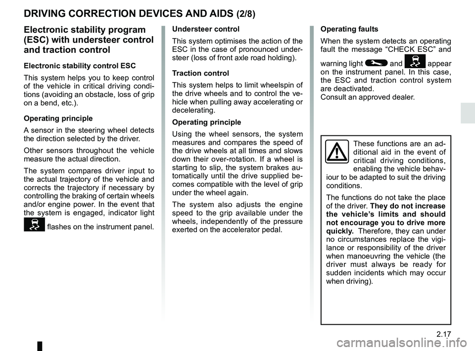
Operating faults
When the system detects an operating
fault the message “CHECK ESC” and
warning light
© and appear
on the instrument panel. In this case,
the ESC and traction control system
are deactivated.
Consult an approved dealer.
Electronic stability program
(ESC) with understeer control
and traction control
Electronic stability control ESC
This system helps you to keep control
of the vehicle in critical driving condi-
tions (avoiding an obstacle, loss of grip
on a bend, etc.).
Operating principle
A sensor in the steering wheel detects
the direction selected by the driver.
Other sensors throughout the vehicle
measure the actual direction.
The system compares driver input to
the actual trajectory of the vehicle and
corrects the trajectory if necessary by
controlling the braking of certain wheels
and/or engine power. In the event that
the system is engaged, indicator light
flashes on the instrument panel.
DRIVING CORRECTION DEVICES AND AIDS (2/8)
Understeer control
This system optimises the action of the
ESC in the case of pronounced under-
steer (loss of front axle road holding).
Traction control
This system helps to limit wheelspin of
the drive wheels and to control the ve-
hicle when pulling away accelerating or
decelerating.
Operating principle
Using the wheel sensors, the system
measures and compares the speed of
the drive wheels at all times and slows
down their over-rotation. If a wheel is
starting to slip, the system brakes au-
tomatically until the drive supplied be-
comes compatible with the level of grip
under the wheel again.
The system also adjusts the engine
speed to the grip available under the
wheels, independently of the pressure
exerted on the accelerator pedal.
These functions are an ad-
ditional aid in the event of
critical driving conditions,
enabling the vehicle behav-
iour to be adapted to suit the driving
conditions.
The functions do not take the place
of the driver. They do not increase
the vehicle’s limits and should
not encourage you to drive more
quickly. Therefore, they can under
no circumstances replace the vigi-
lance or responsibility of the driver
when manoeuvring the vehicle (the
driver must always be ready for
sudden incidents which may occur
when driving).
Page 138 of 290
2.22
DRIVER CORRECTION DEVICES AND AIDS (7/8)
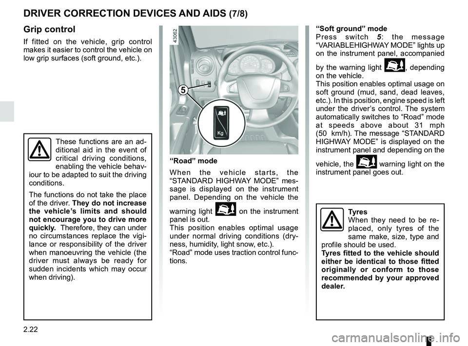
Grip control
If fitted on the vehicle, grip control
makes it easier to control the vehicle on
low grip surfaces (soft ground, etc.).“Soft ground” mode
Press switch
5: the message
“VARIABLEHIGHWAY MODE” lights up
on the instrument panel, accompanied
by the warning light
\b, depending
on the vehicle.
This position enables optimal usage on
soft ground (mud, sand, dead leaves,
etc.). In this position, engine speed is left
under the driver’s control. The system
automatically switches to “Road” mode
at speeds above about 31 mph
(50 km/h). The message “STANDARD
HIGHWAY MODE” is displayed on the
instrument panel and depending on the
vehicle, the
\b warning light on the
instrument panel goes out.
These functions are an ad-
ditional aid in the event of
critical driving conditions,
enabling the vehicle behav-
iour to be adapted to suit the driving
conditions.
The functions do not take the place
of the driver. They do not increase
the vehicle’s limits and should
not encourage you to drive more
quickly. Therefore, they can under
no circumstances replace the vigi-
lance or responsibility of the driver
when manoeuvring the vehicle (the
driver must always be ready for
sudden incidents which may occur
when driving).
“Road” mode
When the vehicle starts, the
“STANDARD HIGHWAY MODE” mes-
sage is displayed on the instrument
panel. Depending on the vehicle the
warning light
\b on the instrument
panel is out.
This position enables optimal usage
under normal driving conditions (dry-
ness, humidity, light snow, etc.).
“Road” mode uses traction control func-
tions.
5
Tyres
When they need to be re-
placed, only tyres of the
same make, size, type and
profile should be used.
Tyres fitted to the vehicle should
either be identical to those fitted
originally or conform to those
recommended by your approved
dealer.
Page 286 of 290
7.4
ALPHABETICAL INDEX (4/4)
service sheets........................................................6.10 → 6.15
signals and lights .................................................1.96 → 1.100
speakers location ...............................................................\
......... 5.40
special features of diesel versions....................................... 2.7
speed limiter ..........................................................2.30 → 2.32
starting the engine ............................................................... 2.3
steering wheel adjustment .............................................................\
...... 1.19
Stop & Start ...............................................................2.4 → 2.6
Stop & Start function..................................................2.4 → 2.6
stopping the engine ............................................................. 2.3
storage compartment.............................................3.20 → 3.25
storage compartments ...........................................3.20 → 3.25
sun visor ........................................................................\
.... 3.18
T
tailgate ...............................................................\
................ 3.29
tank AdBlue .........................................................1.104 → 1.109
tanks and reservoirs: windscreen washer ...................................................... 4.10
technical specifications ..............................6.2 – 6.3, 6.6 → 6.9
temperature regulation ........................................... 3.13 – 3.14
tool kit ........................................................................\
.......... 5.4
towing .................................................................\
............... 3.29 driving ................................................................\
.......... 2.18
breakdown ........................................................ 5.38 – 5.39
towing a caravan ............................................................ 6.8
towing hitch........................................................................\
.. 5.4
towing rings ............................................................ 3.29 – 3.30
towing weights ..................................................................... 6.8
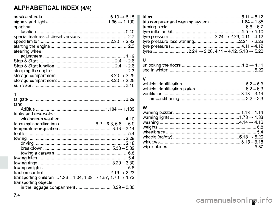
traction control .......................................................2.16 → 2.23
transporting children .... 1.33 – 1.34, 1.38 → 1.57, 1.70 → 1.72
transporting objects in the luggage compartment ............................. 3.29 – 3.30 trims ........................................................................\
5.11 – 5.12
trip computer and warning system.......................... 1.84 – 1.85
turning circle ............................................................... 6.6 – 6.7
tyre inflation kit.........................................................5.5
→ 5.10
tyre pressure...................................... 2.24 → 2.26, 4.11 – 4.12
tyre pressure loss warning.....................................2.24 → 2.26
tyre pressures ......................................................... 4.11 – 4.12
tyres ............................. 2.24 → 2.26, 4.11 – 4.12, 5.18 → 5.20
U
unlocking the doors ................................................. 1.8 → 1.11
use in winter ...................................................................... 5.20
V
vehicle identification ................................................... 6.2 – 6.3
vehicle identification plates ......................................... 6.2 – 6.3
ventilation ............................................................... 3.13 – 3.14 air conditioning ...................................................... 3.2 – 3.3
W
warning buzzer ....................................................... 1.13 – 1.14
warning lights.........................................................1.78 → 1.83
washing ................................................................\
.4.14 → 4.16
weights ................................................................\
................ 6.8
wheelbrace .............................................................\
............. 5.4
wheels (safety) ......................................................5.18 → 5.20
windows .................................................................. 3.15 – 3.16
wiper blades ...................................................................... 5.37