engine RENAULT SCENIC 2000 J64 / 1.G Technical Note 3426A Workshop Manual
[x] Cancel search | Manufacturer: RENAULT, Model Year: 2000, Model line: SCENIC, Model: RENAULT SCENIC 2000 J64 / 1.GPages: 118, PDF Size: 1.5 MB
Page 101 of 118

Downloaded from www.Manualslib.com manuals search engine STARTING - CHARGING
Starter
16
16-4
Starter
IDENTIFICATION
Type Engine Starter motor
XA0 5 F9Q 732 MITSUBISHI M1T85781
Page 102 of 118
Downloaded from www.Manualslib.com manuals search engine STARTING - CHARGING
Starter
16
16-5
REMOVAL
Put the vehicle on a 2 post lift.
Disconnect the battery.
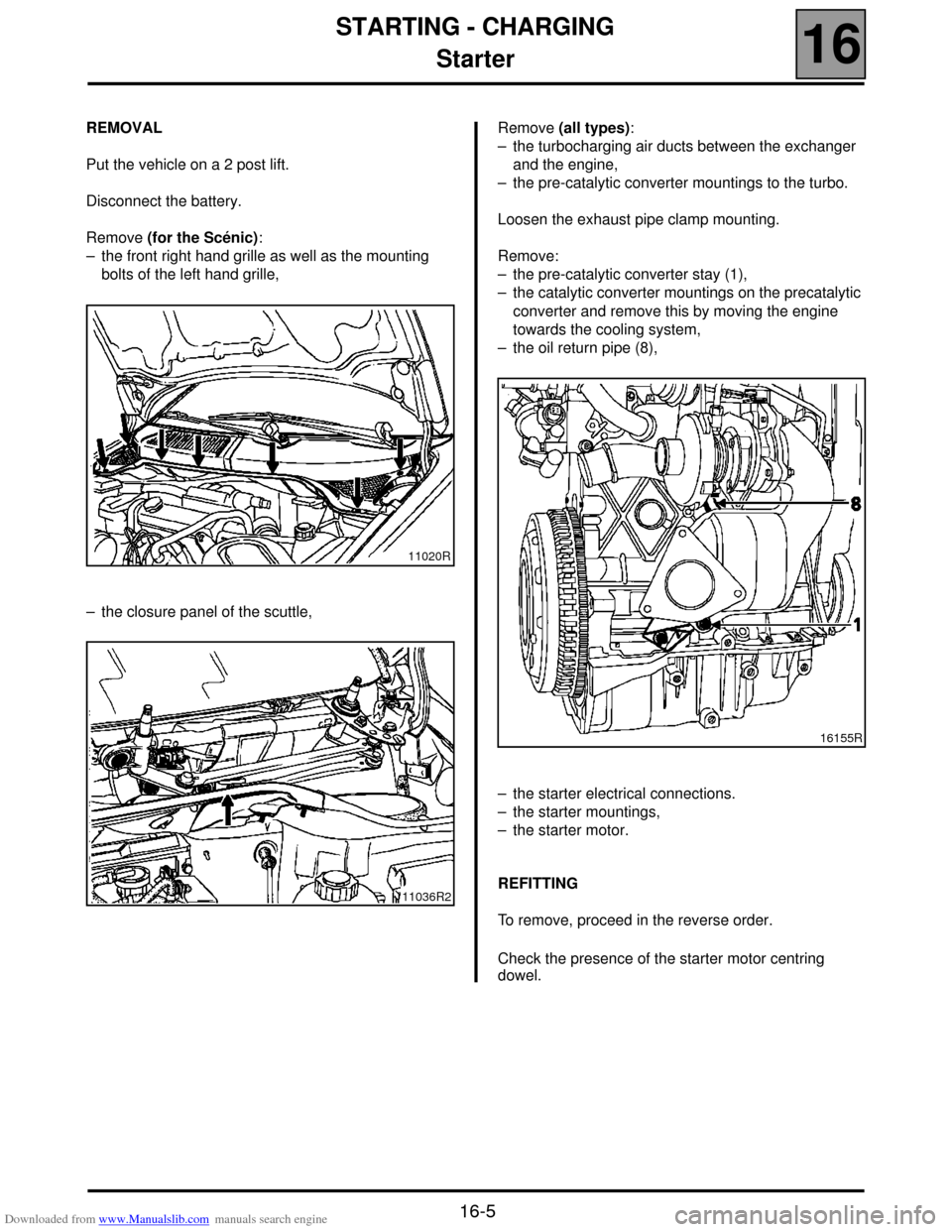
Remove (for the Scénic):
– the front right hand grille as well as the mounting
bolts of the left hand grille,
– the closure panel of the scuttle,Remove (all types):
– the turbocharging air ducts between the exchanger
and the engine,
– the pre-catalytic converter mountings to the turbo.
Loosen the exhaust pipe clamp mounting.
Remove:
– the pre-catalytic converter stay (1),
– the catalytic converter mountings on the precatalytic
converter and remove this by moving the engine
towards the cooling system,
– the oil return pipe (8),
– the starter electrical connections.
– the starter mountings,
– the starter motor.
REFITTING
To remove, proceed in the reverse order.
Check the presence of the starter motor centring
dowel.
11020R
11036R2
16155R
Page 103 of 118

Downloaded from www.Manualslib.com manuals search engine COOLING SYSTEM
Filling and bleeding
19
119 COOLING SYSTEM
Filling and bleeding
There is no heater matrix water control valve.
Water flow is continuous in the heater matrix, which
contributes to the cooling of the engine.
FILLING
It is essential to open the bleed screw on the
cylinder head coolant pipe housing outlet.
Fill the circuit through the expansion bottle opening.
Close the bleed screw as soon as the fluid runs out in
a continuous jet.
Start the engine (2500 rpm).
Adjust the level by overflow for a period of about
4 minutes.
Tighten the expansion bottle cap.
BLEEDING
Let the engine run for 20 minutes at 2500 rpm, until
the engine cooling fan operates (time required for
automatic degassing).
Check the liquid level is at the "Maximum" marker.
DO NOT OPEN THE BLEED SCREW(S) WITH THE
ENGINE RUNNING.
REFIT THE EXPANSION BOTTLE CAP WHILE THE
ENGINE IS WARM.
19-1
Page 104 of 118
Downloaded from www.Manualslib.com manuals search engine COOLING SYSTEM
Diagram
19
19-2
Diagram
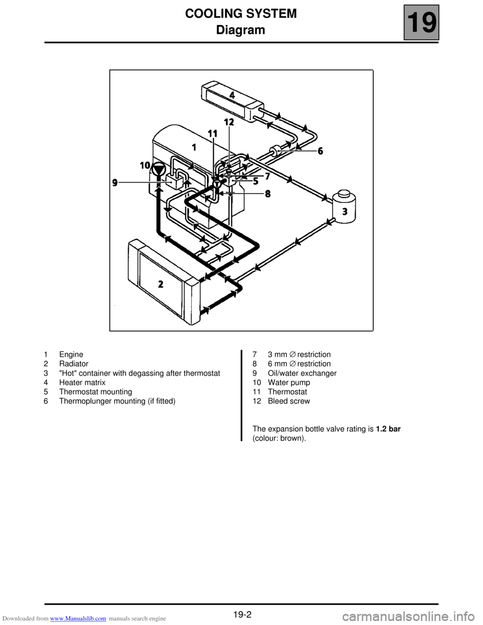
1 Engine
2 Radiator
3 "Hot" container with degassing after thermostat
4 Heater matrix
5 Thermostat mounting
6 Thermoplunger mounting (if fitted)7 3 mm ∅ restriction
8 6 mm ∅ restriction
9 Oil/water exchanger
10 Water pump
11 Thermostat
12 Bleed screw
The expansion bottle valve rating is 1.2 bar
(colour: brown).
Page 105 of 118
Downloaded from www.Manualslib.com manuals search engine COOLING SYSTEM
Thermal plunger unit
19
19-3
Thermal plunger unit
REMOVAL
Put the vehicle on a 2 post lift.
Disconnect the battery.
Remove the engine undertray.
Position the hose clips at the inlet and outlet of the
thermal plunger mounting unit (plugs).
Disconnect the hoses on this unit.
Remove the mounting bolt for the thermal plunger
support unit as well as the supply wires and remove
the unit.
REFITTING
The plugs are tightened in the usual fashion.
Refitting is the reverse of removal.
Top up the coolant and bleed the cooling circuit (see
section 19 "Filling - bleeding"). SPECIAL TOOLING REQUIRED
Mot. 453 -01
Mot. 1202
Mot. 1448Hose clamp pliers set
Hose clip pliers
Long nose pliers for hose clips
TIGHTENING TORQUES (in daN.m)
Thermal plungers 2
Page 106 of 118
Downloaded from www.Manualslib.com manuals search engine COOLING SYSTEM
Radiator
19
19-4
Radiator
REMOVAL
Put the vehicle on a two post lift.
Disconnect the battery.
Remove the engine undertray.
Drain the cooling circuit through the lower radiator
hose.
Disconnect the wiring of the fan unit.
Unclip the power steering reservoir and remove it.
Remove:
– the upper cross member,
– the upper radiator mountings,
– the upper hoses on the radiator,
– the inlet manifold-air exchanger duct,
– the fan unit mountings on the radiator and remove
the fan,
– the radiator mountings on the condenser and remove
the radiator.REFITTING
Refitting is the reverse of removal.
Fill and bleed the cooling circuit (see section 19
"Filling and bleeding").
NOTE: ensure that the fins of the radiator or of the
condenser (if fitted) are not damaged when
removing-refitting, and protect them if necessary. SPECIAL TOOLING REQUIRED
Mot. 1202 -01
Hose clip pliers
Mot. 1202 -02
Mot. 1448 Long nose pliers for hose clips
Page 107 of 118
Downloaded from www.Manualslib.com manuals search engine COOLING SYSTEM
Water pump
19
19-5
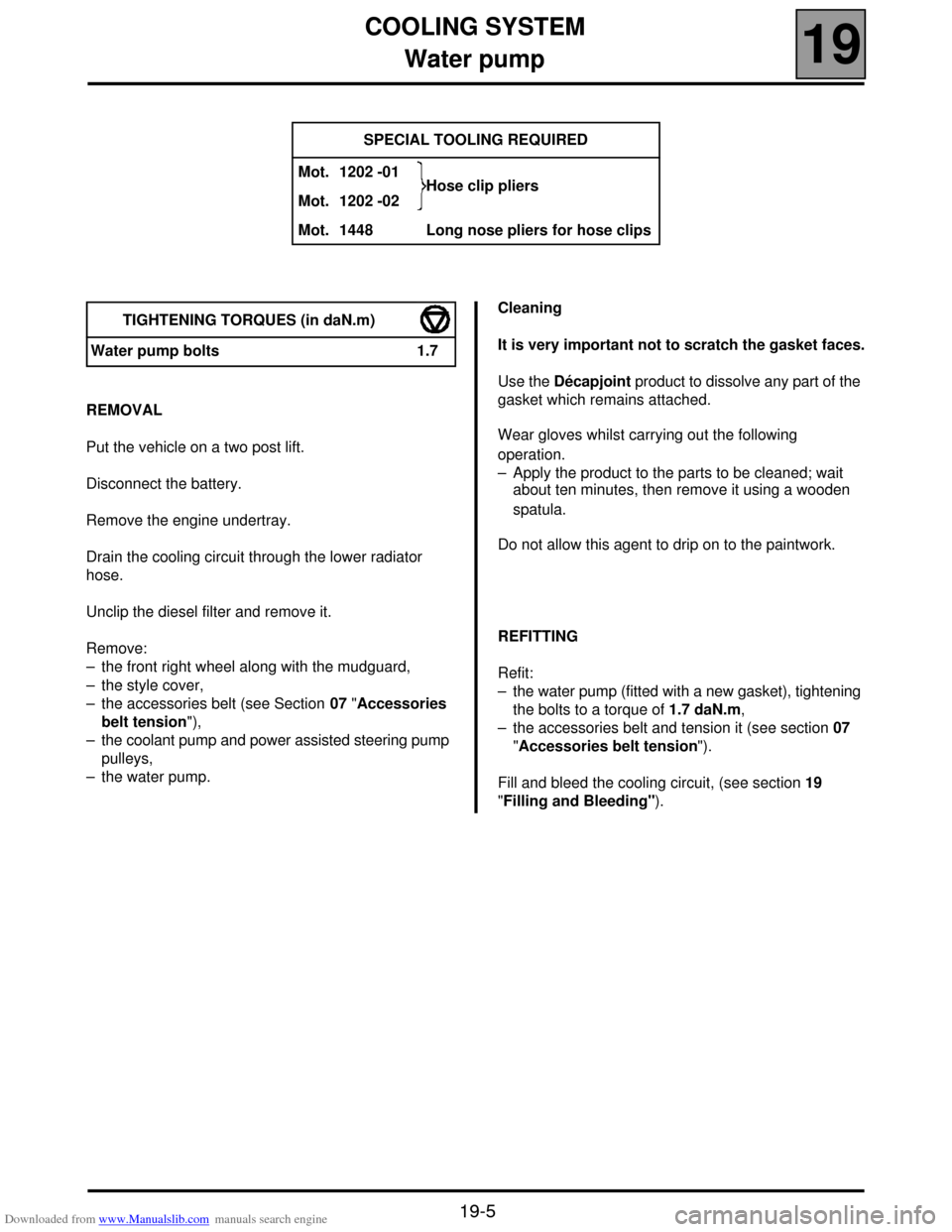
Water pump
REMOVAL
Put the vehicle on a two post lift.
Disconnect the battery.
Remove the engine undertray.
Drain the cooling circuit through the lower radiator
hose.
Unclip the diesel filter and remove it.
Remove:
– the front right wheel along with the mudguard,
– the style cover,
– the accessories belt (see Section 07 "Accessories
belt tension"),
– the coolant pump and power assisted steering pump
pulleys,
– the water pump.Cleaning
It is very important not to scratch the gasket faces.
Use the Décapjoint product to dissolve any part of the
gasket which remains attached.
Wear gloves whilst carrying out the following
operation.
– Apply the product to the parts to be cleaned; wait
about ten minutes, then remove it using a wooden
spatula.
Do not allow this agent to drip on to the paintwork.
REFITTING
Refit:
– the water pump (fitted with a new gasket), tightening
the bolts to a torque of 1.7 daN.m,
– the accessories belt and tension it (see section 07
"Accessories belt tension").
Fill and bleed the cooling circuit, (see section 19
"Filling and Bleeding"). SPECIAL TOOLING REQUIRED
Mot. 1202 -01
Hose clip pliers
Mot. 1202 -02
Mot. 1448 Long nose pliers for hose clips
TIGHTENING TORQUES (in daN.m)
Water pump bolts 1.7
Page 108 of 118
Downloaded from www.Manualslib.com manuals search engine ENGINE MOUNTING
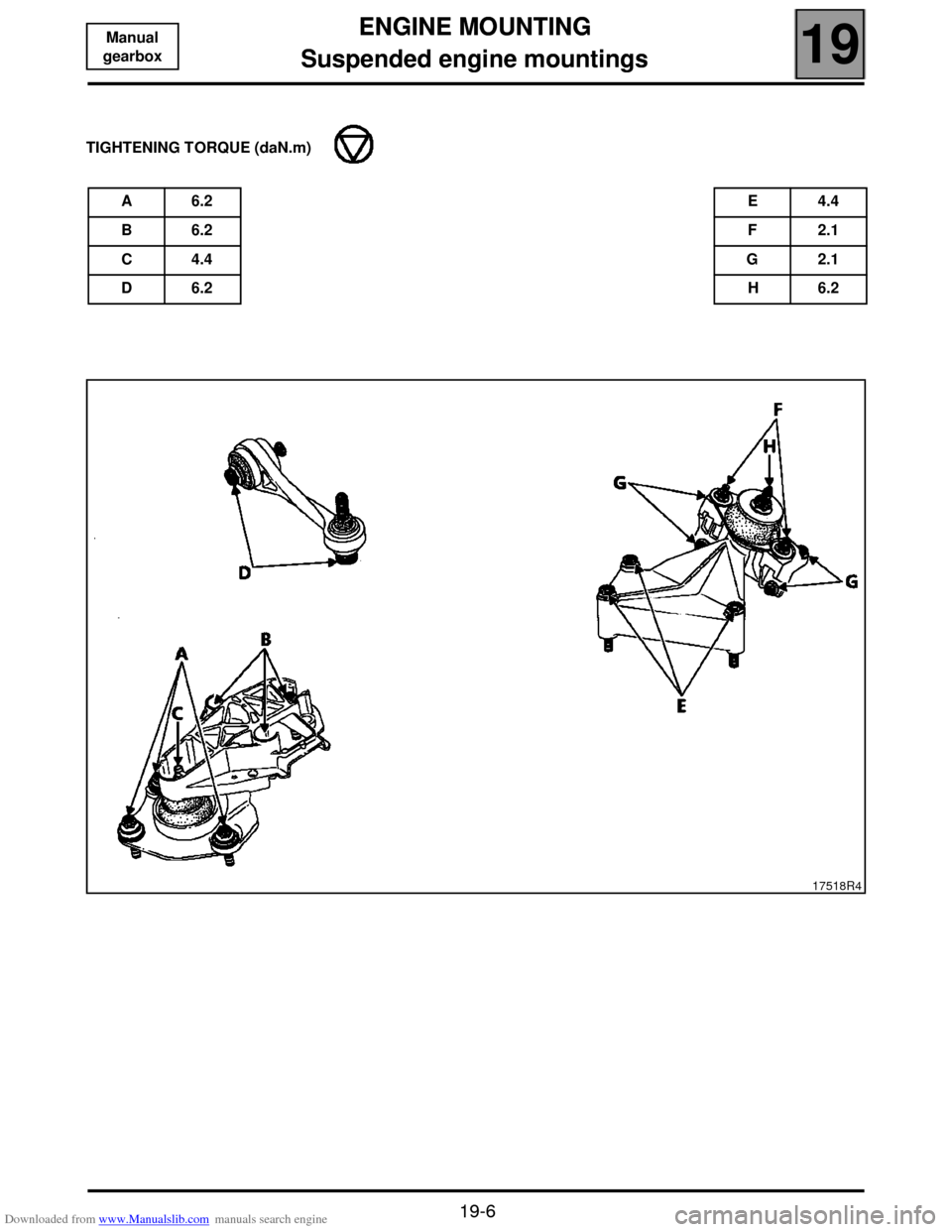
Suspended engine mountings
19
19-6
Manual
gearbox1319 ENGINE MOUNTING
Suspended engine mountings
TIGHTENING TORQUE (daN.m)
A 6.2E 4.4
B 6.2F 2.1
C 4.4G 2.1
D 6.2H 6.2
17518R4
Page 109 of 118
Downloaded from www.Manualslib.com manuals search engine EXHAUST
Catalytic converter
19
19-7
1419 EXHAUST
Catalytic converter
Disconnect the battery and put the vehicle on a two
post lift.
Fit a flywheel immobiliser.
Loosen the catalytic converter/precatalytic converter
mountings.
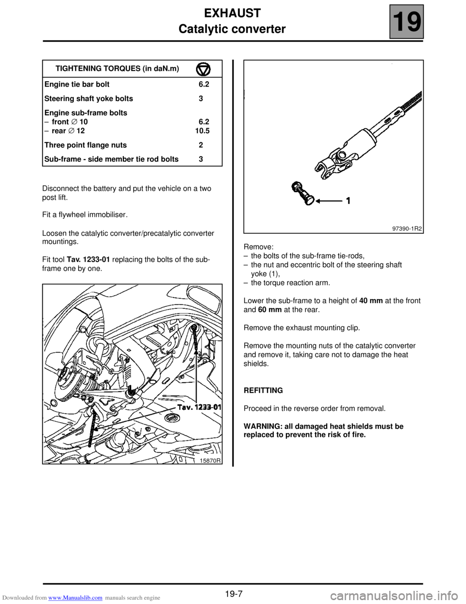
Fit tool Tav. 1233-01 replacing the bolts of the sub-
frame one by one.Remove:
– the bolts of the sub-frame tie-rods,
– the nut and eccentric bolt of the steering shaft
yoke (1),
– the torque reaction arm.
Lower the sub-frame to a height of 40 mm at the front
and 60 mm at the rear.
Remove the exhaust mounting clip.
Remove the mounting nuts of the catalytic converter
and remove it, taking care not to damage the heat
shields.
REFITTING
Proceed in the reverse order from removal.
WARNING: all damaged heat shields must be
replaced to prevent the risk of fire. TIGHTENING TORQUES (in daN.m)
Engine tie bar bolt 6.2
Steering shaft yoke bolts 3
Engine sub-frame bolts
–front ∅ 10
–rear ∅ 12 6.2
10.5
Three point flange nuts 2
Sub-frame - side member tie rod bolts 3
15870R
97390-1R2
Page 110 of 118
Downloaded from www.Manualslib.com manuals search engine MANUAL GEARBOX
Identification
21
21-1
121MANUAL GEARBOX
Identification
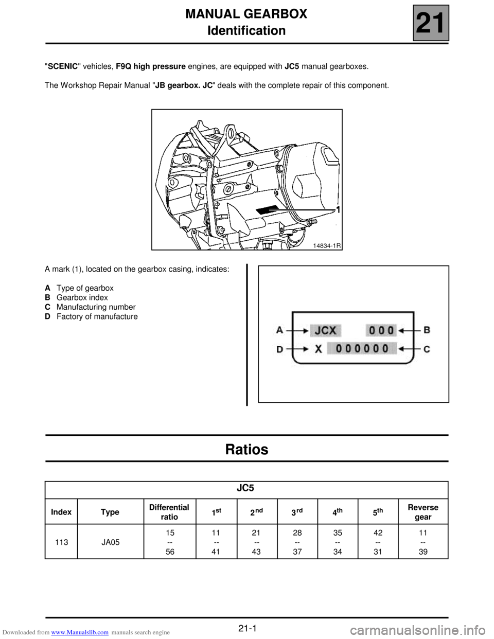
"SCENIC" vehicles, F9Q high pressure engines, are equipped with JC5 manual gearboxes.
The W orkshop Repair Manual "JB gearbox. JC" deals with the complete repair of this component.
A mark (1), located on the gearbox casing, indicates:
AType of gearbox
BGearbox index
CManufacturing number
DFactory of manufacture
Ratios
14834-1R
JC5
Index TypeDifferential
ratio1st2nd3rd4th5thReverse
gear
113 JA0515
--
56 11
--
41 21
--
4328
--
3735
--
34 42
--
3111
--
39