RENAULT SCENIC 2000 J64 / 1.G Technical Note 3426A Workshop Manual
Manufacturer: RENAULT, Model Year: 2000, Model line: SCENIC, Model: RENAULT SCENIC 2000 J64 / 1.GPages: 118, PDF Size: 1.5 MB
Page 1 of 118
Downloaded from www.Manualslib.com manuals search engine © RENAULT 2000
Technical Note 3350A
XA0 5
SPECIAL FEATURES OF F9Q 732 ENGINE
WITH HIGH PRESSURE DIRECT INJECTION
77 11 292 962EDITION ANGLAISE MARCH 2000
Please observe the cleanliness advice
for any operations on this vehicle (section 13).
This Technical Note cancels and replaces Technical Note 3245A
For all parts not dealt with in this Technical Note refer to Workshop Repair Manual MR 312.
Consult Technical Note 3341A for the diagnostic part.
"The repair methods given by the manufacturer in this document are based on the
technical specifications current when it was prepared.
The methods may be modified as a result of changes introduced by the manufacturer in
the production of the various component units and accessories from which his vehicles
are constructed."All copyrights reserved by Renault.
Copying or translating, in part or in full, of this document or use of the service part
reference numbering system is forbidden without the prior written authority of Renault.
Page 2 of 118
Downloaded from www.Manualslib.com manuals search engine Contents
Page
07
10
11
12
VALUES AND SETTINGS
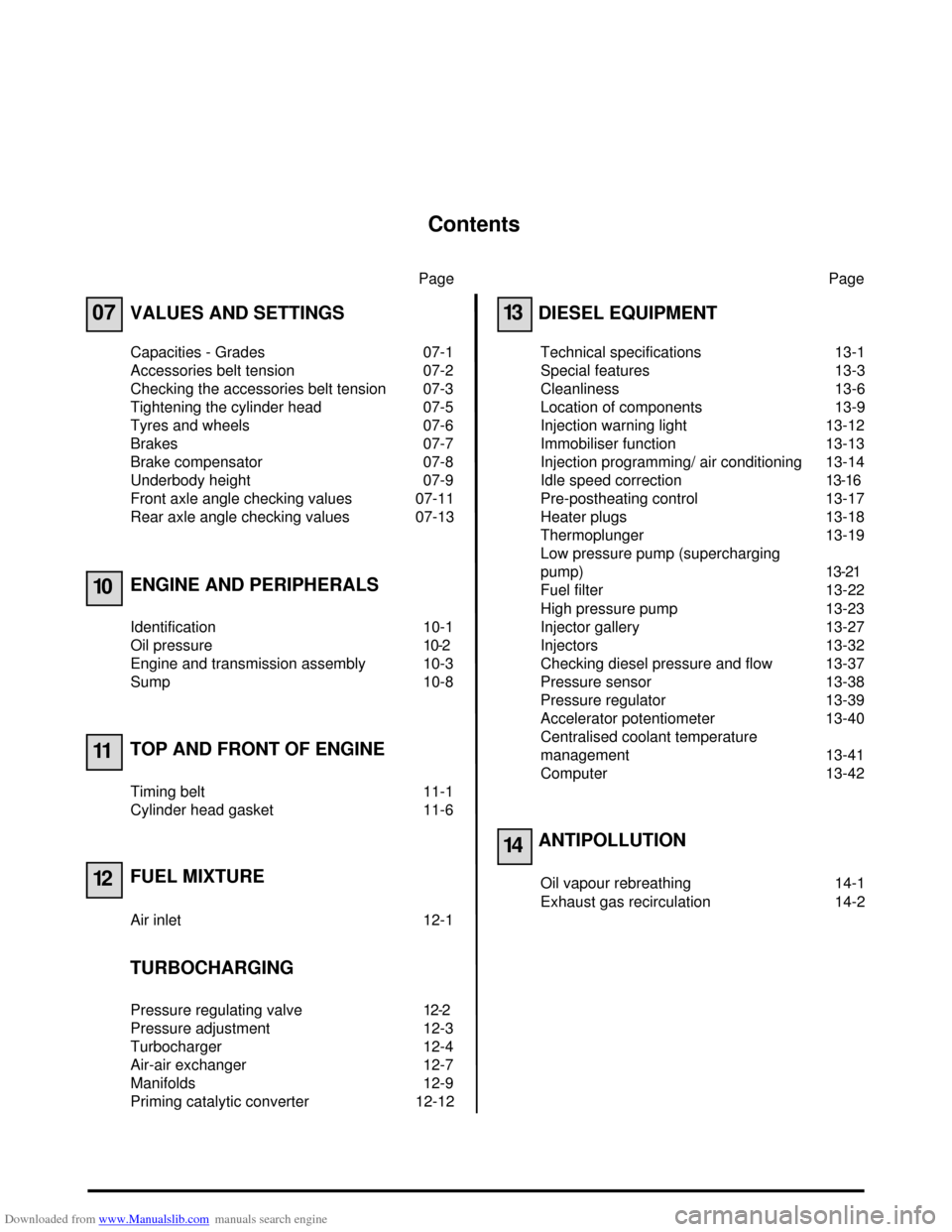
Capacities - Grades 07-1
Accessories belt tension 07-2
Checking the accessories belt tension 07-3
Tightening the cylinder head 07-5
Tyres and wheels 07-6
Brakes 07-7
Brake compensator 07-8
Underbody height 07-9
Front axle angle checking values 07-11
Rear axle angle checking values 07-13
ENGINE AND PERIPHERALS
Identification 10-1
Oil pressure 10-2
Engine and transmission assembly 10-3
Sump 10-8
TOP AND FRONT OF ENGINE
Timing belt 11-1
Cylinder head gasket 11-6
FUEL MIXTURE
Air inlet 12-1
TURBOCHARGING
Pressure regulating valve 12-2
Pressure adjustment 12-3
Turbocharger 12-4
Air-air exchanger 12-7
Manifolds 12-9
Priming catalytic converter 12-12Page
13
14
DIESEL EQUIPMENT
Technical specifications 13-1
Special features 13-3
Cleanliness 13-6
Location of components 13-9
Injection warning light 13-12
Immobiliser function 13-13
Injection programming/ air conditioning 13-14
Idle speed correction13-16
Pre-postheating control 13-17
Heater plugs 13-18
Thermoplunger 13-19
Low pressure pump (supercharging
pump)13-21
Fuel filter 13-22
High pressure pump 13-23
Injector gallery 13-27
Injectors 13-32
Checking diesel pressure and flow 13-37
Pressure sensor 13-38
Pressure regulator 13-39
Accelerator potentiometer 13-40
Centralised coolant temperature
management 13-41
Computer 13-42
ANTIPOLLUTION
Oil vapour rebreathing 14-1
Exhaust gas recirculation 14-2
Page 3 of 118
Downloaded from www.Manualslib.com manuals search engine Contents
Page
16
19
21
62
STARTING - CHARGING
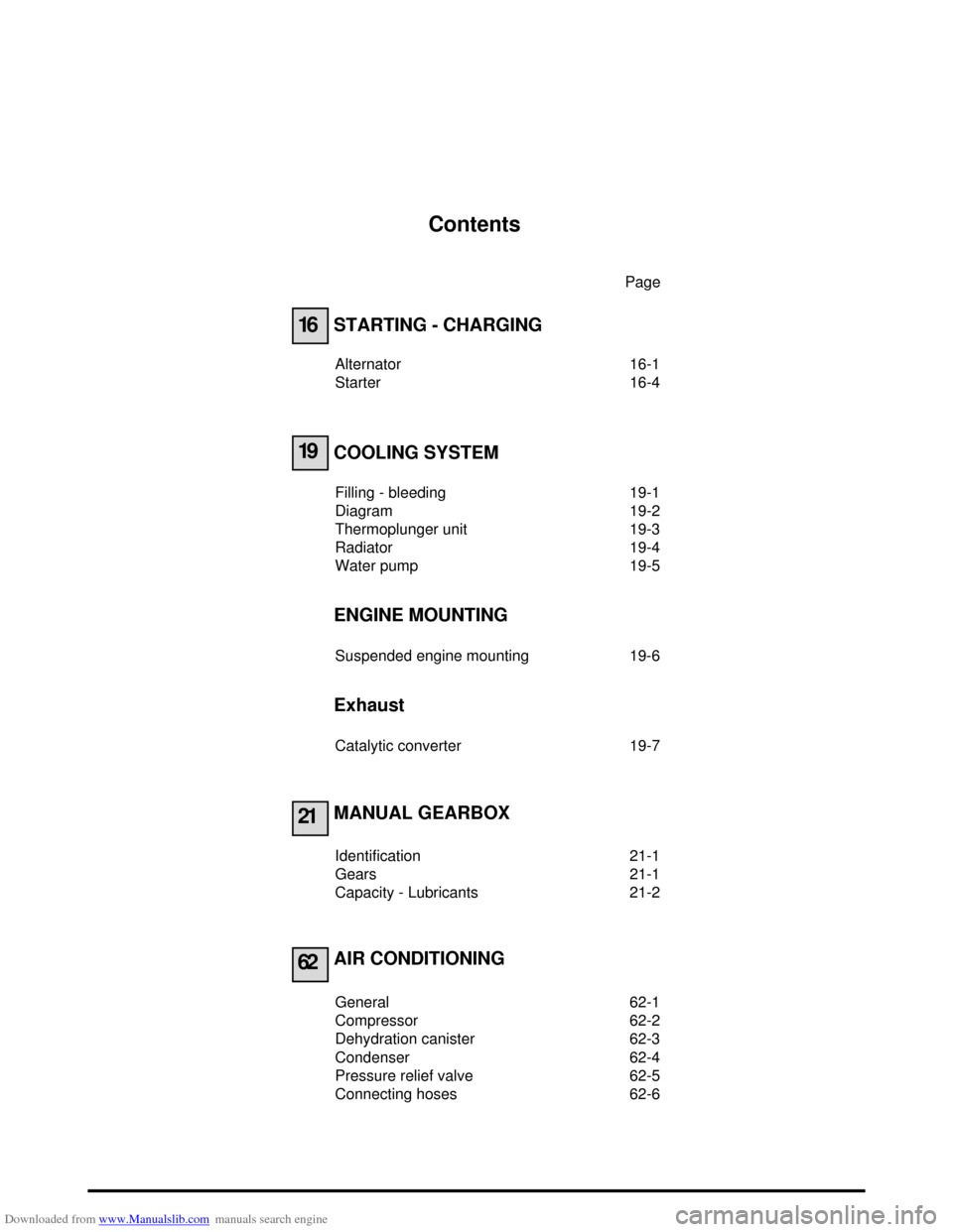
Alternator 16-1
Starter 16-4
COOLING SYSTEM
Filling - bleeding 19-1
Diagram 19-2
Thermoplunger unit 19-3
Radiator 19-4
Water pump 19-5
ENGINE MOUNTING
Suspended engine mounting 19-6
Exhaust
Catalytic converter 19-7
MANUAL GEARBOX
Identification 21-1
Gears 21-1
Capacity - Lubricants 21-2
AIR CONDITIONING
General 62-1
Compressor 62-2
Dehydration canister 62-3
Condenser 62-4
Pressure relief valve 62-5
Connecting hoses 62-6
Page 4 of 118
Downloaded from www.Manualslib.com manuals search engine VALUES AND SETTINGS
Capacities - Grades
07
107
VALUES AND SETTINGS
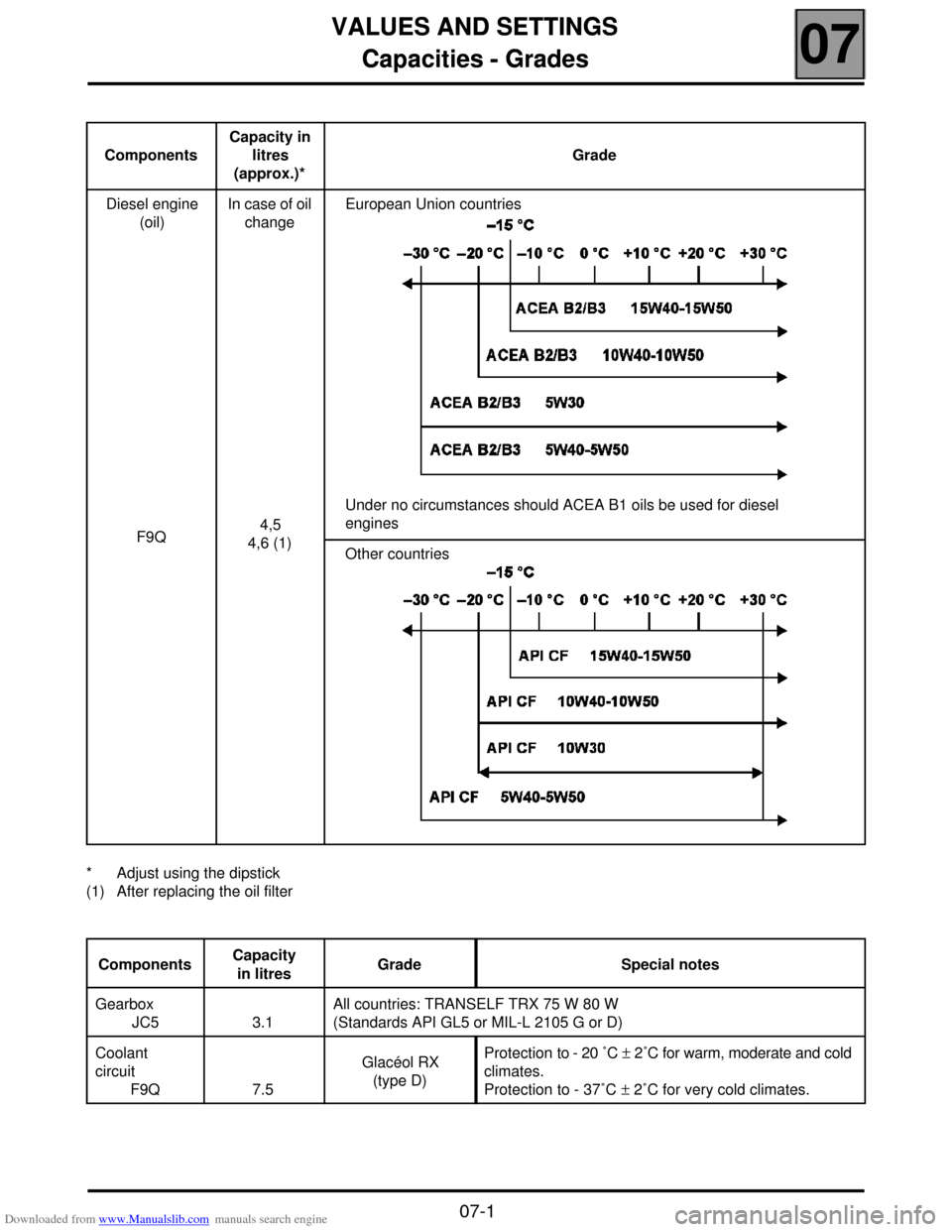
Capacities - Grades
* Adjust using the dipstick
(1) After replacing the oil filterComponentsCapacity in
litres
(approx.)*Grade
Diesel engine
(oil)
F9QIn case of oil
change
4,5
4,6 (1)European Union countries
Under no circumstances should ACEA B1 oils be used for diesel
engines
Other countries
ComponentsCapacity
in litresGrade Special notes
Gearbox
JC5 3.1All countries: TRANSELF TRX 75 W 80 W
(Standards API GL5 or MIL-L 2105 G or D)
Coolant
circuit
F9Q 7.5Glacéol RX
(type D)Protection to - 20 ˚C ± 2˚C for warm, moderate and cold
climates.
Protection to - 37˚C ± 2˚C for very cold climates.
07-1
Page 5 of 118
Downloaded from www.Manualslib.com manuals search engine VALUES AND SETTINGS
Accessories belt tensioning
07
07-2
WITHOUT AIR
CONDITIONING
Accessories belt tensioning
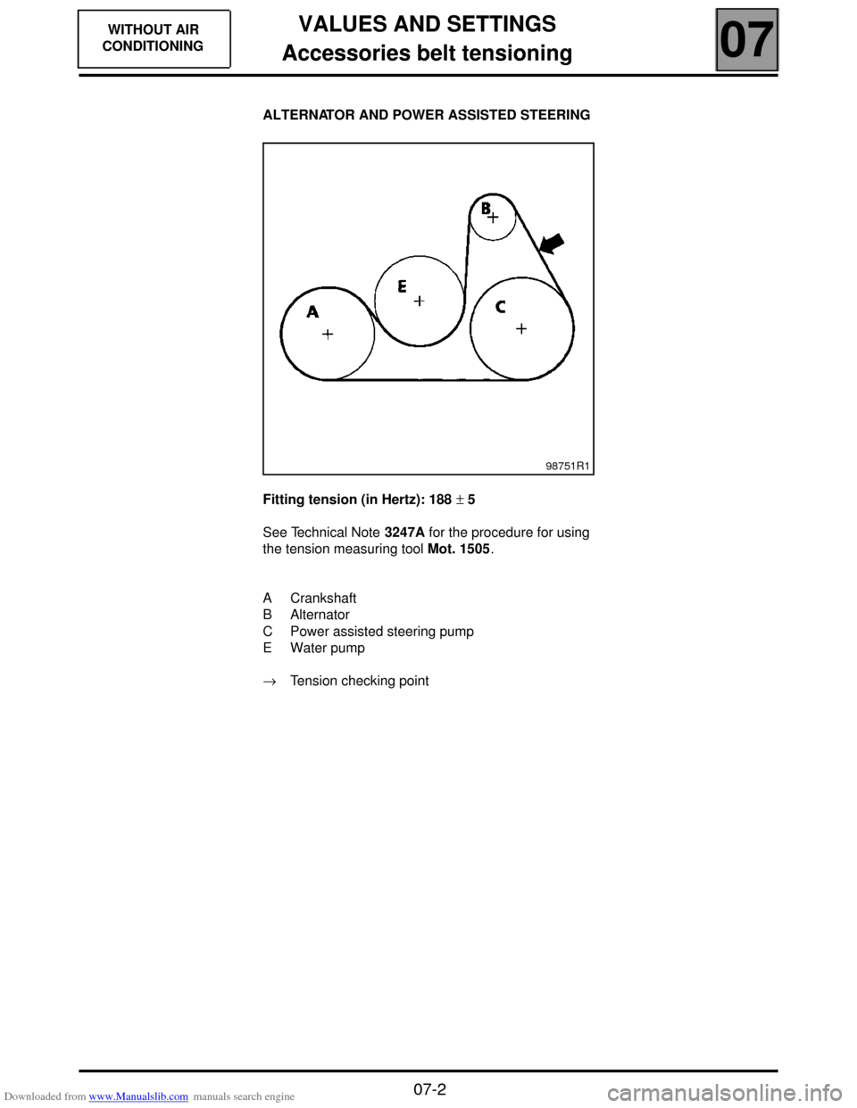
ALTERNATOR AND POWER ASSISTED STEERING
Fitting tension (in Hertz): 188 ± 5
See Technical Note 3247A for the procedure for using
the tension measuring tool Mot. 1505.
A Crankshaft
B Alternator
C Power assisted steering pump
E Water pump
→ Tension checking point
98751R1
Page 6 of 118
Downloaded from www.Manualslib.com manuals search engine VALUES AND SETTINGS
Checking the accessories belt tension
07
07-3
WITH AIR
CONDITIONING
Checking the accessories belt tension
SPECIAL TOOLING REQUIRED
Mot. 1387 Tool for checking the automatic
tension wheel centreline
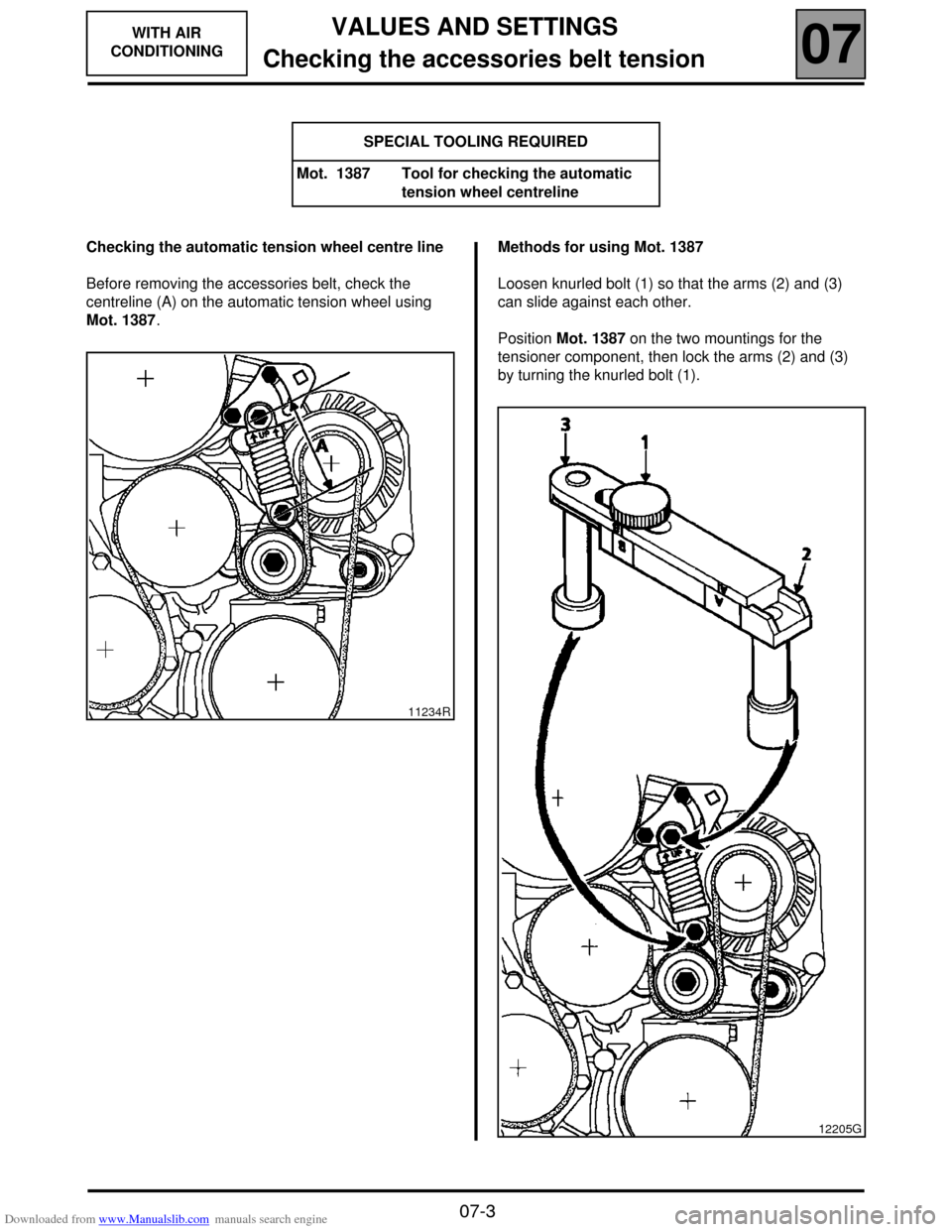
Checking the automatic tension wheel centre line
Before removing the accessories belt, check the
centreline (A) on the automatic tension wheel using
Mot. 1387.Methods for using Mot. 1387
Loosen knurled bolt (1) so that the arms (2) and (3)
can slide against each other.
Position Mot. 1387 on the two mountings for the
tensioner component, then lock the arms (2) and (3)
by turning the knurled bolt (1).
11234R
12205G
Page 7 of 118
Downloaded from www.Manualslib.com manuals search engine VALUES AND SETTINGS
Checking the accessories belt tension
07
07-4
WITH AIR
CONDITIONING
Checking the accessories belt tension
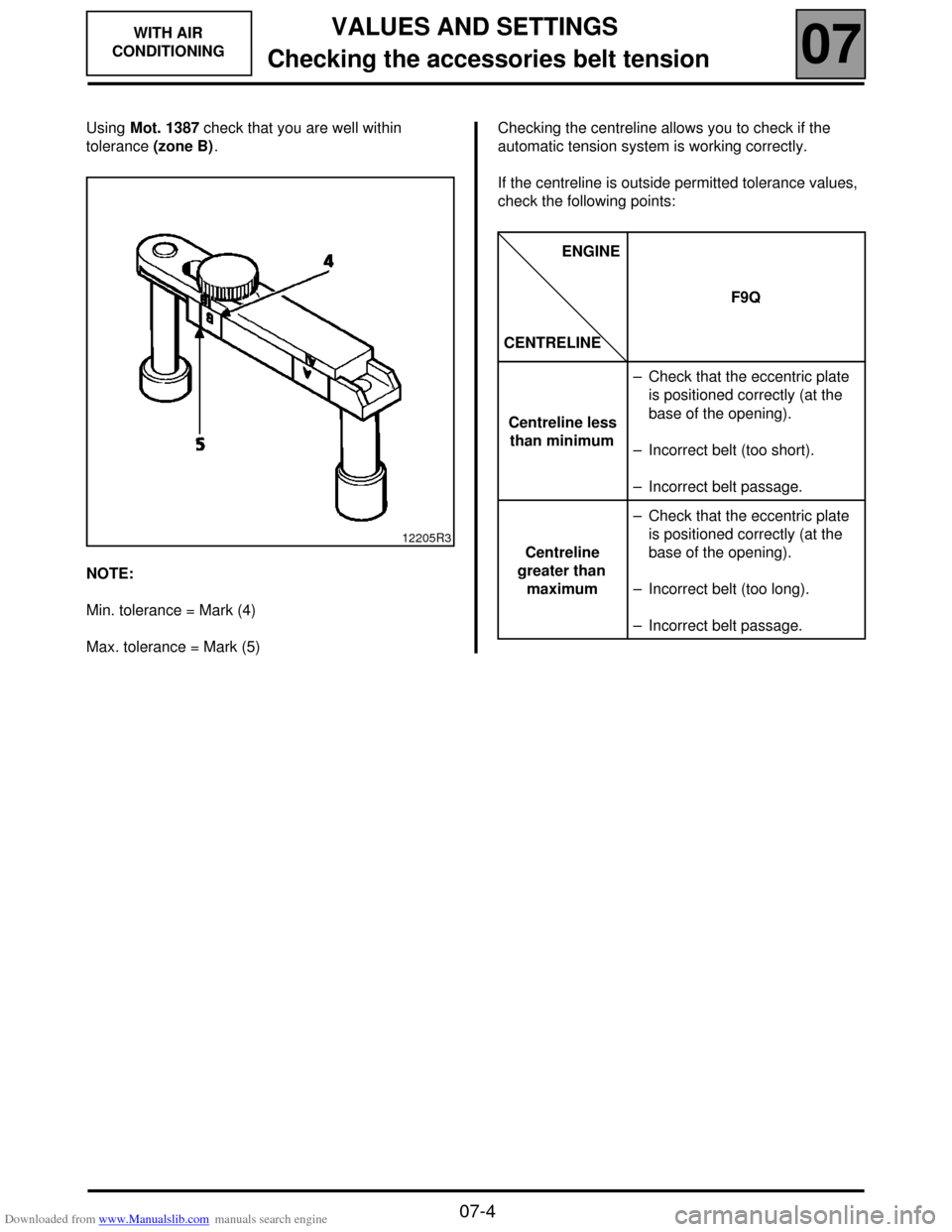
Using Mot. 1387 check that you are well within
tolerance (zone B).
NOTE:
Min. tolerance = Mark (4)
Max. tolerance = Mark (5)Checking the centreline allows you to check if the
automatic tension system is working correctly.
If the centreline is outside permitted tolerance values,
check the following points:
12205R3
ENGINE
CENTRELINEF9Q
Centreline less
than minimum– Check that the eccentric plate
is positioned correctly (at the
base of the opening).
– Incorrect belt (too short).
– Incorrect belt passage.
Centreline
greater than
maximum– Check that the eccentric plate
is positioned correctly (at the
base of the opening).
– Incorrect belt (too long).
– Incorrect belt passage.
Page 8 of 118
Downloaded from www.Manualslib.com manuals search engine VALUES AND SETTINGS
Tightening the cylinder head
07
07-5
Tightening the cylinder head
METHOD FOR TIGHTENING THE CYLINDER HEAD
REMINDER: in order to tighten the bolts correctly, use
a syringe to remove any oil which may have entered
the cylinder head mounting bolt holes.
All the cylinder head bolts must always be changed
after removal. There is no cylinder head retightening
operation.
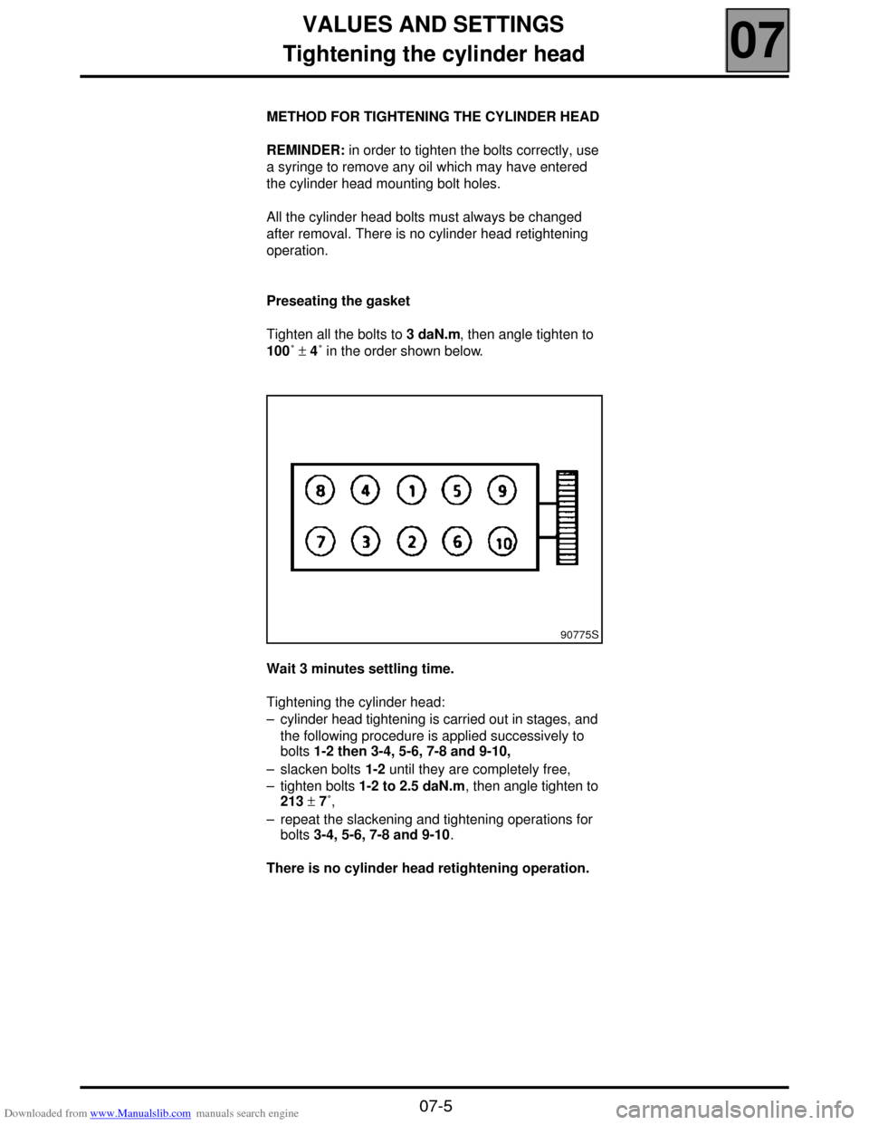
Preseating the gasket
Tighten all the bolts to 3 daN.m, then angle tighten to
100˚ ± 4˚ in the order shown below.
Wait 3 minutes settling time.
Tightening the cylinder head:
– cylinder head tightening is carried out in stages, and
the following procedure is applied successively to
bolts 1-2 then 3-4, 5-6, 7-8 and 9-10,
– slacken bolts 1-2 until they are completely free,
– tighten bolts 1-2 to 2.5 daN.m, then angle tighten to
213 ± 7˚,
– repeat the slackening and tightening operations for
bolts 3-4, 5-6, 7-8 and 9-10.
There is no cylinder head retightening operation.
90775S
Page 9 of 118

Downloaded from www.Manualslib.com manuals search engine VALUES AND SETTINGS
Tyres and wheels
07
07-6
Tyres and wheels
(1) With full load and on motorways.
Tightening torque for wheel nuts: 9 daN.m
Rim run-out: 1.2 mm Type Rim TyresTyre pressure when
cold (in bar) (1)
Front Rear
BA05 6 J 15 185/60 R 15 2.4 2.2
JA05 6 J 15 185/60 R 15 2.3 2.3
Page 10 of 118
Downloaded from www.Manualslib.com manuals search engine VALUES AND SETTINGS
Brakes
07
07-7
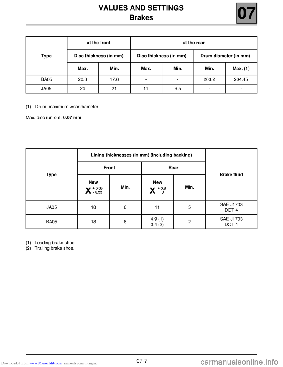
Brakes
(1) Drum: maximum wear diameter
Max. disc run-out: 0.07 mm
(1) Leading brake shoe.
(2) Trailing brake shoe.Typeat the front at the rear
Disc thickness (in mm) Disc thickness (in mm) Drum diameter (in mm)
Max. Min. Max. Min. Min. Max. (1)
BA05 20.6 17.6 - - 203.2 204.45
JA05 24 21 11 9.5 - -
TypeLining thicknesses (in mm) (including backing)
Brake fluid Front Rear
New
Min.New
Min.
JA05 18 6 11 5 SAE J1703
DOT 4
BA05 18 6 4.9 (1)
3.4 (2)2 SAE J1703
DOT 4