brake RENAULT SCENIC 2000 J64 / 1.G Technical Note 3426A Workshop Manual
[x] Cancel search | Manufacturer: RENAULT, Model Year: 2000, Model line: SCENIC, Model: RENAULT SCENIC 2000 J64 / 1.GPages: 118, PDF Size: 1.5 MB
Page 2 of 118
Downloaded from www.Manualslib.com manuals search engine Contents
Page
07
10
11
12
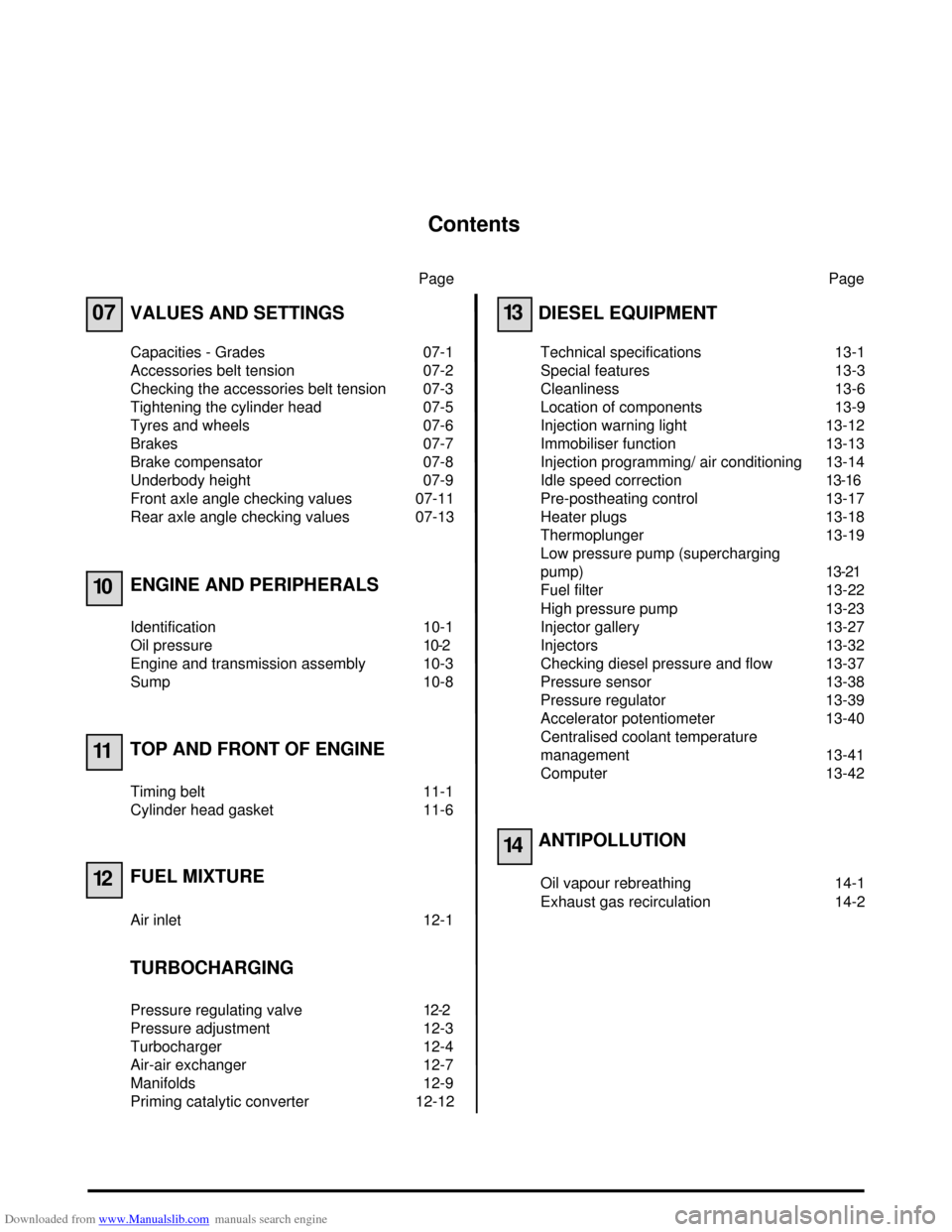
VALUES AND SETTINGS
Capacities - Grades 07-1
Accessories belt tension 07-2
Checking the accessories belt tension 07-3
Tightening the cylinder head 07-5
Tyres and wheels 07-6
Brakes 07-7
Brake compensator 07-8
Underbody height 07-9
Front axle angle checking values 07-11
Rear axle angle checking values 07-13
ENGINE AND PERIPHERALS
Identification 10-1
Oil pressure 10-2
Engine and transmission assembly 10-3
Sump 10-8
TOP AND FRONT OF ENGINE
Timing belt 11-1
Cylinder head gasket 11-6
FUEL MIXTURE
Air inlet 12-1
TURBOCHARGING
Pressure regulating valve 12-2
Pressure adjustment 12-3
Turbocharger 12-4
Air-air exchanger 12-7
Manifolds 12-9
Priming catalytic converter 12-12Page
13
14
DIESEL EQUIPMENT
Technical specifications 13-1
Special features 13-3
Cleanliness 13-6
Location of components 13-9
Injection warning light 13-12
Immobiliser function 13-13
Injection programming/ air conditioning 13-14
Idle speed correction13-16
Pre-postheating control 13-17
Heater plugs 13-18
Thermoplunger 13-19
Low pressure pump (supercharging
pump)13-21
Fuel filter 13-22
High pressure pump 13-23
Injector gallery 13-27
Injectors 13-32
Checking diesel pressure and flow 13-37
Pressure sensor 13-38
Pressure regulator 13-39
Accelerator potentiometer 13-40
Centralised coolant temperature
management 13-41
Computer 13-42
ANTIPOLLUTION
Oil vapour rebreathing 14-1
Exhaust gas recirculation 14-2
Page 10 of 118
Downloaded from www.Manualslib.com manuals search engine VALUES AND SETTINGS
Brakes
07
07-7
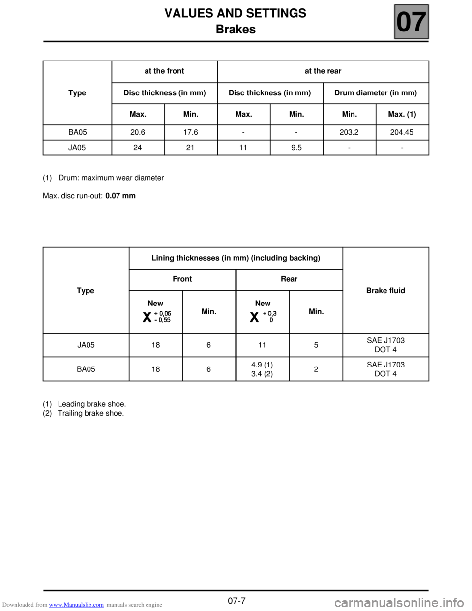
Brakes
(1) Drum: maximum wear diameter
Max. disc run-out: 0.07 mm
(1) Leading brake shoe.
(2) Trailing brake shoe.Typeat the front at the rear
Disc thickness (in mm) Disc thickness (in mm) Drum diameter (in mm)
Max. Min. Max. Min. Min. Max. (1)
BA05 20.6 17.6 - - 203.2 204.45
JA05 24 21 11 9.5 - -
TypeLining thicknesses (in mm) (including backing)
Brake fluid Front Rear
New
Min.New
Min.
JA05 18 6 11 5 SAE J1703
DOT 4
BA05 18 6 4.9 (1)
3.4 (2)2 SAE J1703
DOT 4
Page 11 of 118

Downloaded from www.Manualslib.com manuals search engine VALUES AND SETTINGS
Brake compensator
07
07-8
Brake compensator
BRAKING PRESSURE
Conditions:
– Full fuel tank,
– Driver on board.
(1) The test is performed using two pressure gauges in an X arrangement.TypeCheck pressure (1) (in bars)
Front Rear
B0A5 140
+18 52 0
JA05 140 +18 32 0
Page 12 of 118
Downloaded from www.Manualslib.com manuals search engine VALUES AND SETTINGS
Underbody height
07
07-9
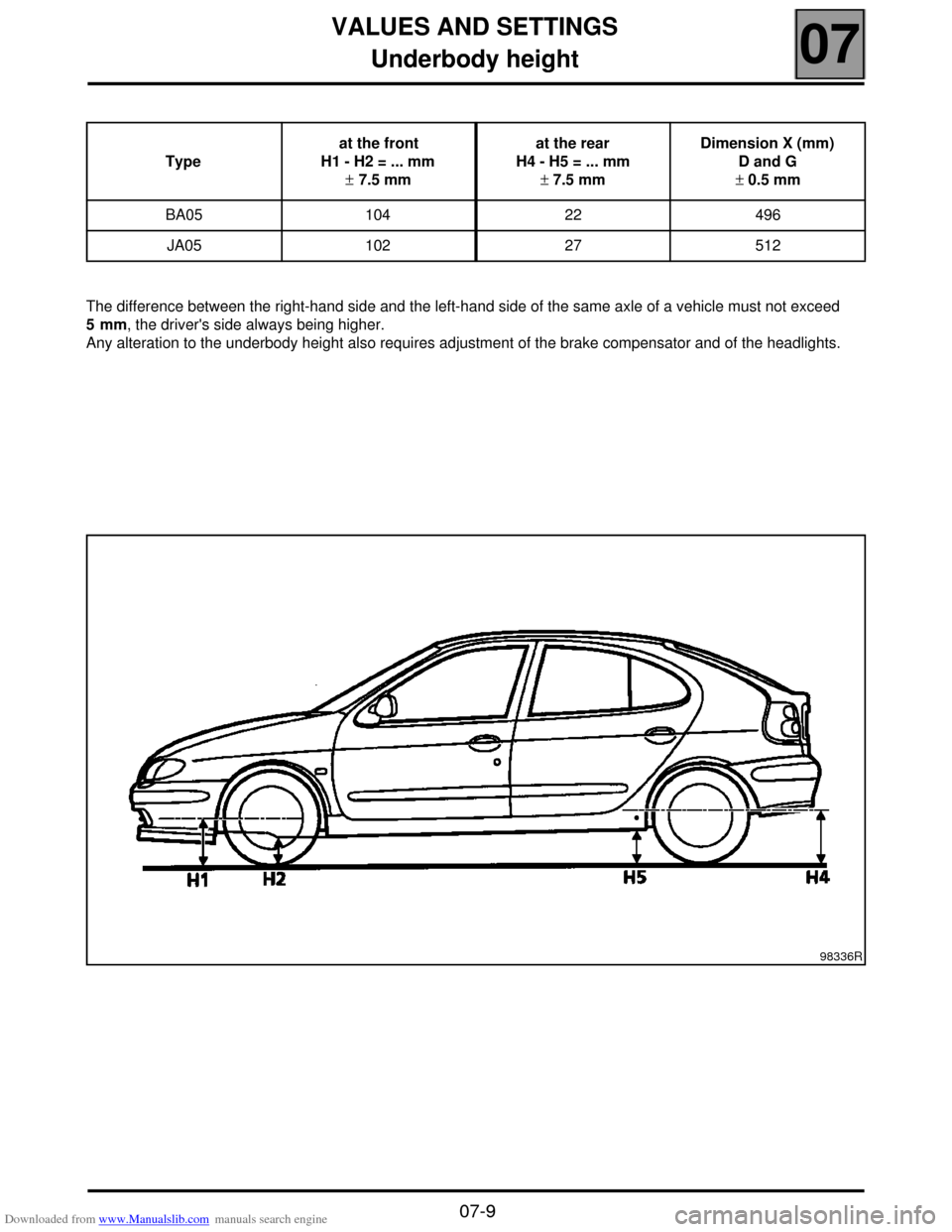
Underbody height
The difference between the right-hand side and the left-hand side of the same axle of a vehicle must not exceed
5 mm, the driver's side always being higher.
Any alteration to the underbody height also requires adjustment of the brake compensator and of the headlights.Typeat the front
H1 - H2 = ... mm
± 7.5 mmat the rear
H4 - H5 = ... mm
± 7.5 mmDimension X (mm)
D and G
± 0.5 mm
BA05 104 22 496
JA05 102 27 512
98336R
Page 19 of 118
Downloaded from www.Manualslib.com manuals search engine ENGINE AND PERIPHERALS
Engine and transmission assembly
10
10-3
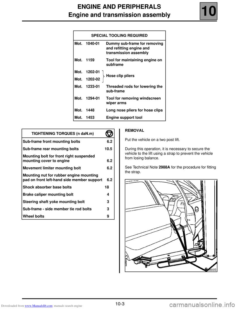
Engine and transmission assembly
SPECIAL TOOLING REQUIRED
Mot. 1040-01 Dummy sub-frame for removing
and refitting engine and
transmission assembly
Mot. 1159 Tool for maintaining engine on
subframe
Mot. 1202-01
Hose clip pliers
Mot. 1202-02
Mot. 1233-01 Threaded rods for lowering the
sub-frame
Mot. 1294-01 Tool for removing windscreen
wiper arms
Mot. 1448 Long nose pliers for hose clips
Mot. 1453 Engine support tool
REMOVAL
Put the vehicle on a two post lift.
During this operation, it is necessary to secure the
vehicle to the lift using a strap to prevent the vehicle
from losing balance.
See Technical Note 2988A for the procedure for fitting
the strap. TIGHTENING TORQUES (n daN.m)
Sub-frame front mounting bolts 6.2
Sub-frame rear mounting bolts 10.5
Mounting bolt for front right suspended
mounting cover to engine 6.2
Movement limiter mounting bolt 6.2
Mounting nut for rubber engine mounting
pad on front left-hand side member support 6.2
Shock absorber base bolts 18
Brake caliper mounting bolt 4
Steering shaft yoke mounting bolt 3
Sub-frame - side member tie rod bolts 3
Wheel bolts 9
14893S
Page 20 of 118
Downloaded from www.Manualslib.com manuals search engine ENGINE AND PERIPHERALS
Engine and transmission assembly
10
10-4
Remove:
– the battery,
– the engine undertray.
Drain:
– the cooling circuit through the bottom hose of the
radiator,
– the gearbox and the engine (if necessary),
– the refrigerant circuit (if fitted) using filling equipment.
Remove:
– the front wheels along with the mudguard,
– the sub-frame and body tie rods,
– the track rod ends,
– the brake calipers (as well as the ABS sensors, if
fitted) and secure them to the suspension springs,
– the shock absorber base bolts,
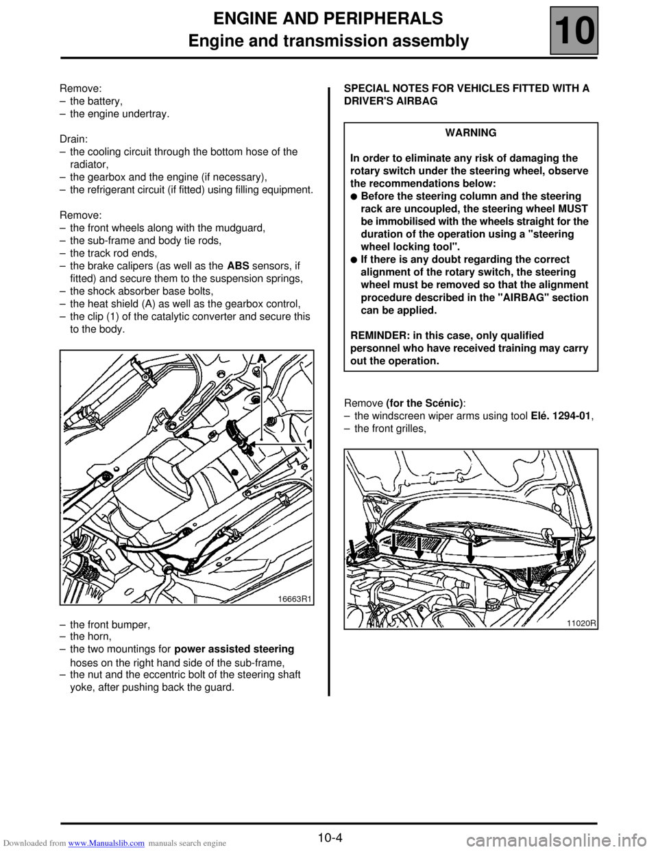
– the heat shield (A) as well as the gearbox control,
– the clip (1) of the catalytic converter and secure this
to the body.
– the front bumper,
– the horn,
– the two mountings for power assisted steering
hoses on the right hand side of the sub-frame,
– the nut and the eccentric bolt of the steering shaft
yoke, after pushing back the guard.SPECIAL NOTES FOR VEHICLES FITTED WITH A
DRIVER'S AIRBAG
Remove (for the Scénic):
– the windscreen wiper arms using tool Elé. 1294-01,
– the front grilles,
16663R1
WARNING
In order to eliminate any risk of damaging the
rotary switch under the steering wheel, observe
the recommendations below:
!Before the steering column and the steering
rack are uncoupled, the steering wheel MUST
be immobilised with the wheels straight for the
duration of the operation using a "steering
wheel locking tool".
!If there is any doubt regarding the correct
alignment of the rotary switch, the steering
wheel must be removed so that the alignment
procedure described in the "AIRBAG" section
can be applied.
REMINDER: in this case, only qualified
personnel who have received training may carry
out the operation.
11020R
Page 21 of 118
Downloaded from www.Manualslib.com manuals search engine ENGINE AND PERIPHERALS
Engine and transmission assembly
10
10-5
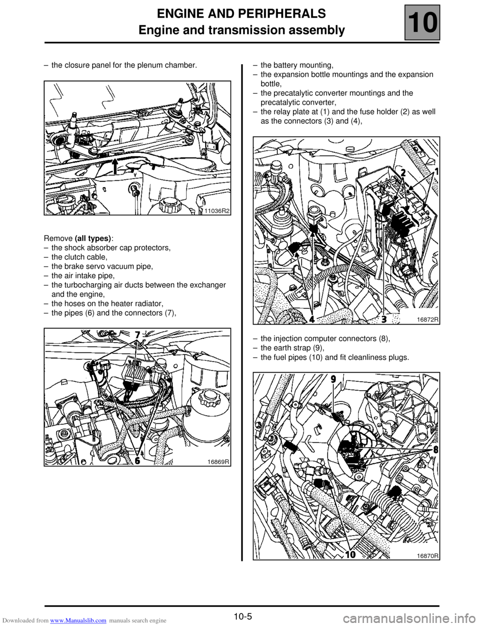
– the closure panel for the plenum chamber.
Remove (all types):
– the shock absorber cap protectors,
– the clutch cable,
– the brake servo vacuum pipe,
– the air intake pipe,
– the turbocharging air ducts between the exchanger
and the engine,
– the hoses on the heater radiator,
– the pipes (6) and the connectors (7),– the battery mounting,
– the expansion bottle mountings and the expansion
bottle,
– the precatalytic converter mountings and the
precatalytic converter,
– the relay plate at (1) and the fuse holder (2) as well
as the connectors (3) and (4),
– the injection computer connectors (8),
– the earth strap (9),
– the fuel pipes (10) and fit cleanliness plugs.
11036R2
16869R
16872R
16870R
Page 23 of 118
Downloaded from www.Manualslib.com manuals search engine ENGINE AND PERIPHERALS
Engine and transmission assembly
10
10-7
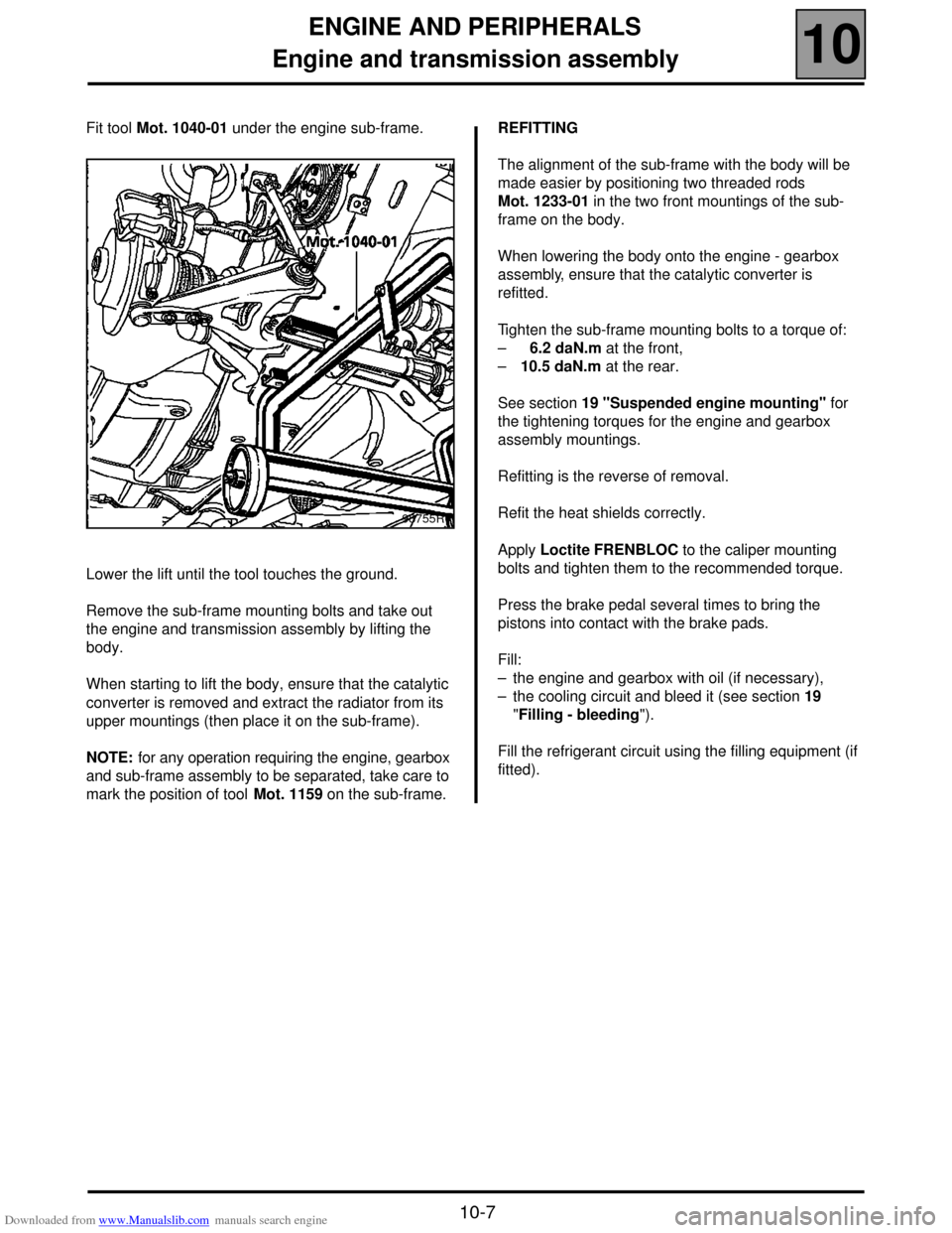
Fit tool Mot. 1040-01 under the engine sub-frame.
Lower the lift until the tool touches the ground.
Remove the sub-frame mounting bolts and take out
the engine and transmission assembly by lifting the
body.
When starting to lift the body, ensure that the catalytic
converter is removed and extract the radiator from its
upper mountings (then place it on the sub-frame).
NOTE: for any operation requiring the engine, gearbox
and sub-frame assembly to be separated, take care to
mark the position of tool Mot. 1159 on the sub-frame.REFITTING
The alignment of the sub-frame with the body will be
made easier by positioning two threaded rods
Mot. 1233-01 in the two front mountings of the sub-
frame on the body.
When lowering the body onto the engine - gearbox
assembly, ensure that the catalytic converter is
refitted.
Tighten the sub-frame mounting bolts to a torque of:
– 6.2 daN.m at the front,
–10.5 daN.m at the rear.
See section 19 "Suspended engine mounting" for
the tightening torques for the engine and gearbox
assembly mountings.
Refitting is the reverse of removal.
Refit the heat shields correctly.
Apply Loctite FRENBLOC to the caliper mounting
bolts and tighten them to the recommended torque.
Press the brake pedal several times to bring the
pistons into contact with the brake pads.
Fill:
– the engine and gearbox with oil (if necessary),
– the cooling circuit and bleed it (see section 19
"Filling - bleeding").
Fill the refrigerant circuit using the filling equipment (if
fitted).
98755R1
Page 35 of 118
Downloaded from www.Manualslib.com manuals search engine TOP AND FRONT OF ENGINE
Cylinder head gasket
11
11 - 9
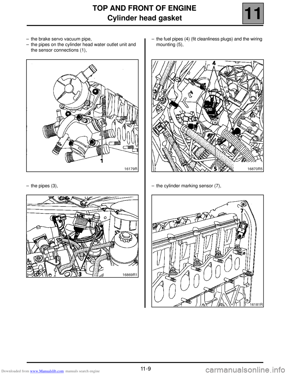
– the brake servo vacuum pipe,
– the pipes on the cylinder head water outlet unit and
the sensor connections (1),
– the pipes (3),– the fuel pipes (4) (fit cleanliness plugs) and the wiring
mounting (5),
– the cylinder marking sensor (7),
16179R
16869R116870R5
16181R
Page 67 of 118
Downloaded from www.Manualslib.com manuals search engine DIESEL EQUIPMENT
Idle speed correction
13
13-16
Idle speed correction
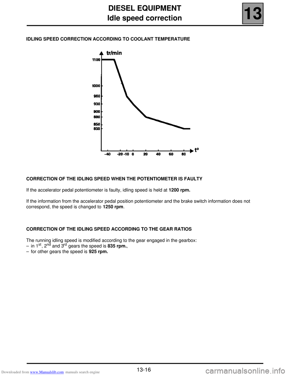
IDLING SPEED CORRECTION ACCORDING TO COOLANT TEMPERATURE
CORRECTION OF THE IDLING SPEED WHEN THE POTENTIOMETER IS FAULTY
If the accelerator pedal potentiometer is faulty, idling speed is held at 1200 rpm.
If the information from the accelerator pedal position potentiometer and the brake switch information does not
correspond, the speed is changed to 1250 rpm.
CORRECTION OF THE IDLING SPEED ACCORDING TO THE GEAR RATIOS
The running idling speed is modified according to the gear engaged in the gearbox:
– in 1
st, 2nd and 3rd gears the speed is 835 rpm.,
– for other gears the speed is 925 rpm.