heating RENAULT SCENIC 2000 J64 / 1.G Technical Note 3426A Workshop Manual
[x] Cancel search | Manufacturer: RENAULT, Model Year: 2000, Model line: SCENIC, Model: RENAULT SCENIC 2000 J64 / 1.GPages: 118, PDF Size: 1.5 MB
Page 2 of 118
Downloaded from www.Manualslib.com manuals search engine Contents
Page
07
10
11
12
VALUES AND SETTINGS
Capacities - Grades 07-1
Accessories belt tension 07-2
Checking the accessories belt tension 07-3
Tightening the cylinder head 07-5
Tyres and wheels 07-6
Brakes 07-7
Brake compensator 07-8
Underbody height 07-9
Front axle angle checking values 07-11
Rear axle angle checking values 07-13
ENGINE AND PERIPHERALS
Identification 10-1
Oil pressure 10-2
Engine and transmission assembly 10-3
Sump 10-8
TOP AND FRONT OF ENGINE
Timing belt 11-1
Cylinder head gasket 11-6
FUEL MIXTURE
Air inlet 12-1
TURBOCHARGING
Pressure regulating valve 12-2
Pressure adjustment 12-3
Turbocharger 12-4
Air-air exchanger 12-7
Manifolds 12-9
Priming catalytic converter 12-12Page
13
14
DIESEL EQUIPMENT
Technical specifications 13-1
Special features 13-3
Cleanliness 13-6
Location of components 13-9
Injection warning light 13-12
Immobiliser function 13-13
Injection programming/ air conditioning 13-14
Idle speed correction13-16
Pre-postheating control 13-17
Heater plugs 13-18
Thermoplunger 13-19
Low pressure pump (supercharging
pump)13-21
Fuel filter 13-22
High pressure pump 13-23
Injector gallery 13-27
Injectors 13-32
Checking diesel pressure and flow 13-37
Pressure sensor 13-38
Pressure regulator 13-39
Accelerator potentiometer 13-40
Centralised coolant temperature
management 13-41
Computer 13-42
ANTIPOLLUTION
Oil vapour rebreathing 14-1
Exhaust gas recirculation 14-2
Page 52 of 118

Downloaded from www.Manualslib.com manuals search engine DIESEL EQUIPMENT
Specifications
13
113
DIESEL EQUIPMENT
Specifications
Vehicle GearboxEngine
Depollution
standard
Type IndexBore
(mm) Stroke
(mm) Cubic
capacity
(cm
3)Compres-
sion ratioCatalytic
converter
XA05 JC5 F9Q 732 80 93 1 870 19/1◊ C103 Euro 2000
ENGINE SPEED (rpm) SMOKE DENSITY
IDLING SPEED Max. - no loadMax. - under
loadHomologation value Max. - Max
835 ± 50 4,700 ± 150 4,500 ± 100
1.5 m
-1 (46 %) 3 m-1 (70 %)
DESCRIPTION BRAND/TYPE SPECIAL NOTES
High pressure pumpBOSCH
CR/CP153/R65/10-15Pressure from 250 to 1350 bars
Supercharging pump (low
pressure)BOSCHPressure from 2.5 to 4 bars
Flow: 80 to 100 litres/hour minimum
Diesel pressure sensor BOSCHFitted to the injection rail
Resistance: tracks 1,2 and 1,3 = 4.3 MΩ
tracks 2,3 = 1050 Ω
Injectors BOSCHSolenoid injector
Resistance: < 2 Ω
Maximum pressure 1525 bars
Pressure regulator - Integrated with the high pressure pump
Resistance: ≈ 5 Ω at 20˚ C
Injection computer BOSCH128 track computer
Pre-postheating unit NAGARES BED/7With pre-postheating function controlled by the
injection computer
Heater plugsBERU
or
CHAMPIONResistance: 0.6 Ω connector removed
Accelerator potentiometer CTSDouble track potentiometer
Track resistance ≈ 1.7 Ω
Air intake temperature sensor SIEMENSintegrated in the flow meter
Resistance between 100 Ω and 40 Ω
13-1
Page 60 of 118
Downloaded from www.Manualslib.com manuals search engine DIESEL EQUIPMENT
Location of components
13
13-9
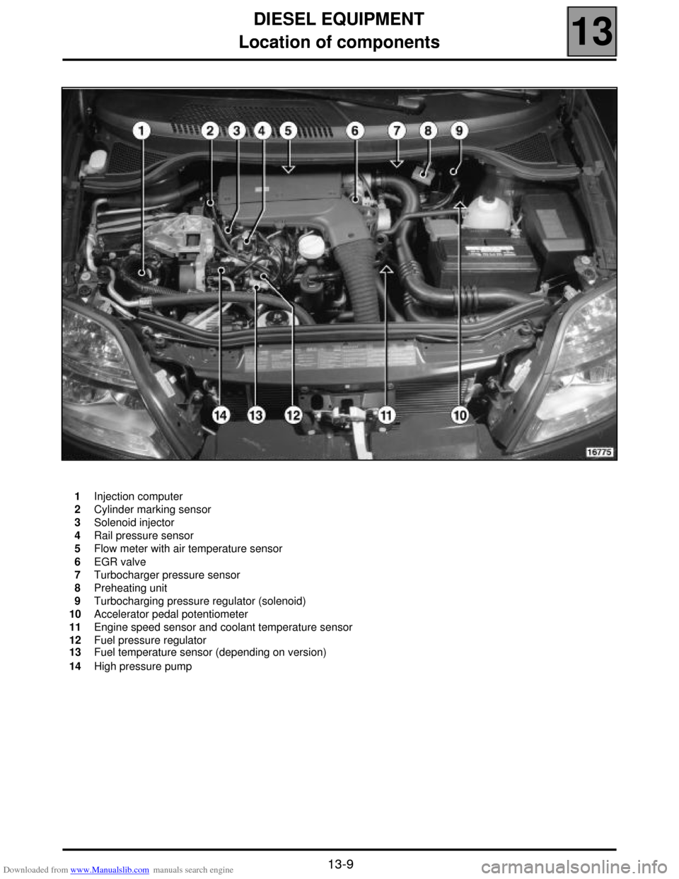
Location of components
1
2
3
4
5
6
7
8
9
10
11
12
13
14Injection computer
Cylinder marking sensor
Solenoid injector
Rail pressure sensor
Flow meter with air temperature sensor
EGR valve
Turbocharger pressure sensor
Preheating unit
Turbocharging pressure regulator (solenoid)
Accelerator pedal potentiometer
Engine speed sensor and coolant temperature sensor
Fuel pressure regulator
Fuel temperature sensor (depending on version)
High pressure pump
Page 62 of 118
Downloaded from www.Manualslib.com manuals search engine DIESEL EQUIPMENT
Location of components
13
13-11
16181R
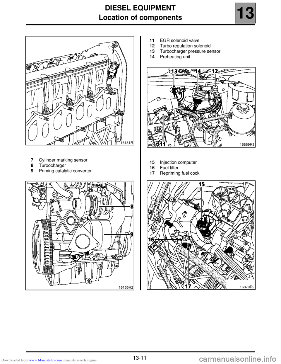
7
8
9Cylinder marking sensor
Turbocharger
Priming catalytic converter
16155R2
11
12
13
14EGR solenoid valve
Turbo regulation solenoid
Turbocharger pressure sensor
Preheating unit
16869R3
15
16
17Injection computer
Fuel filter
Repriming fuel cock
16870R2
Page 63 of 118

Downloaded from www.Manualslib.com manuals search engine DIESEL EQUIPMENT
Injection warning light
13
13-12
Injection warning light
Vehicles using the high pressure diesel system are fitted with two injection warning lights used during the preheating
phase and in case of an injection fault (or engine overheating).
WARNING LIGHT PRINCIPLE
!When ignition is switched on, the preheating light is lit during the preheating phase and then goes out (see section
13 "Pre-postheating control").
!When there is a fault on the injection system the "fault" warning light lights up. These faults are:
– internal computer fault,
– engine speed fault (the vehicle doesn't start),
– main relay or low pressure fault (the vehicle doesn't start),
– injector fault,
–TDC sensor coherence fault and camshaft sensor,
– rail pressure sensor fault,
– rail pressure regulator fault,
– accelerator potentiometer fault,
– engine immobiliser fault,
– computer supply voltage fault,
– engine overheating.
NOTE: the OBD warning light (symbolised by an engine), visible when the ignition is switched on, is never visible
when the engine is running.
Page 68 of 118
Downloaded from www.Manualslib.com manuals search engine DIESEL EQUIPMENT
Pre-postheating control
13
13-17
Pre-postheating control
The pre-postheating function is controlled by the preheating unit.
OPERATING PRINCIPLE FOR PRE-POST HEATING
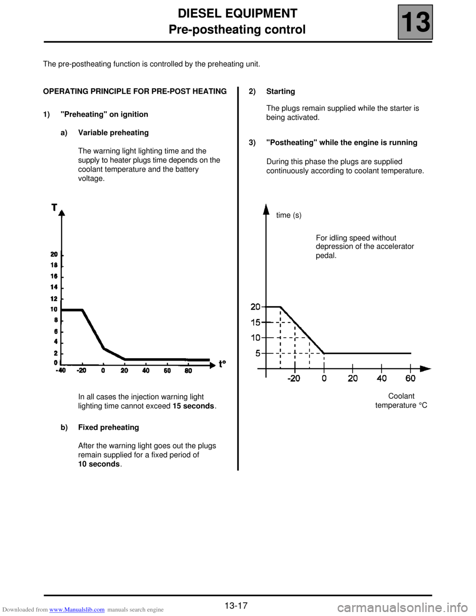
1) "Preheating" on ignition
a) Variable preheating
The warning light lighting time and the
supply to heater plugs time depends on the
coolant temperature and the battery
voltage.
In all cases the injection warning light
lighting time cannot exceed 15 seconds.
b) Fixed preheating
After the warning light goes out the plugs
remain supplied for a fixed period of
10 seconds.2) Starting
The plugs remain supplied while the starter is
being activated.
3) "Postheating" while the engine is running
During this phase the plugs are supplied
continuously according to coolant temperature.
time (s)
Coolant
temperature °C For idling speed without
depression of the accelerator
pedal.
Page 70 of 118
Downloaded from www.Manualslib.com manuals search engine DIESEL EQUIPMENT
Thermal plunger
13
13-19
Thermal plunger
The three thermal plungers are located on a water unit
fixed under the manifold at the engine - gearbox joint.
The objective of the system is to reheat the coolant.
The thermal plungers are supplied with 12 volts by
two relays. One relay controls two thermal plungers,
and the other relay controls one thermal plunger. This
enables control of one, two or three thermal plungers
as required.
The resistance of the thermal plungers is:
0.45 ± 0.05 Ω at 20˚C. Control strategy
When the thermal plungers are operating the idling
speed is brought to 900 rpm.
Thermal plungers cannot operate in the case of:
– preheating,
– post heating,
– heated windscreen selected,
– engine speed below 700 rpm.,
If the conditions mentioned above apply, the thermal
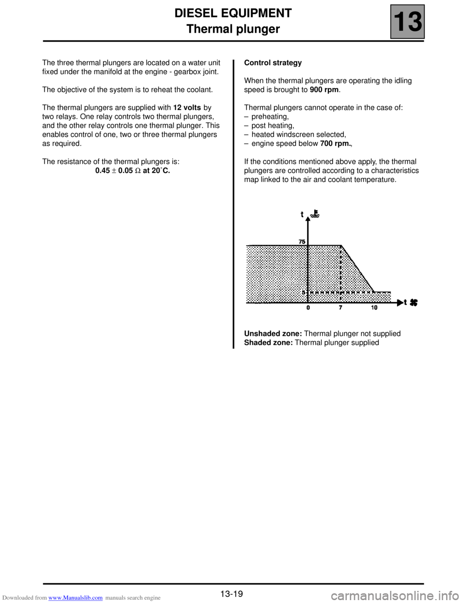
plungers are controlled according to a characteristics
map linked to the air and coolant temperature.
Unshaded zone: Thermal plunger not supplied
Shaded zone: Thermal plunger supplied
Page 93 of 118
Downloaded from www.Manualslib.com manuals search engine DIESEL EQUIPMENT
Computer
13
13-42
Computer
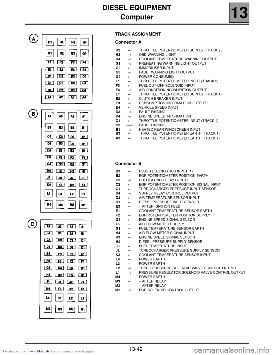
TRACK ASSIGNMENT
Connector A
H2
H3
H4
G1
G2
G3
G4
F1
F3
F4
E1
E2
E3
E4
D3
D4
C1
C3
B1
B3
A3---
→
→
→
←
→
←
←
←
→
---
←
→
←
→←
→
←
→←
→
---
---THROTTLE POTENTIOMETER SUPPLY (TRACK 2)
OBD WARNING LIGHT
COOLANT TEMPERATURE WARNING OUTPUT
PREHEATING WARNING LIGHT OUTPUT
IMMOBILISER INPUT
FAULT WARNING LIGHT OUTPUT
POWER CONSUMED
THROTTLE POTENTIOMETER INPUT (TRACK 2)
FUEL CUT-OFF SOLENOID INPUT
AIR CONDITIONING INHIBITION OUTPUT
THROTTLE POTENTIOMETER SUPPLY (TRACK 1)
CLUTCH BREAKER INPUT
CONSUMPTION INFORMATION OUTPUT
VEHICLE SPEED INPUT
FAULT FINDING
ENGINE SPEED INFORMATION
THROTTLE POTENTIOMETER INPUT (TRACK 1)
FAULT FINDING
HEATED REAR WINDSCREEN INPUT
THROTTLE POTENTIOMETER EARTH (TRACK 1)
THROTTLE POTENTIOMETER EARTH (TRACK 2)
Connector B
B3
B2
C3
C2
C1
D4
D3
D1
E3
E1
F2
G3
G2
G1
H4
H3
H2
J3
J2
K3
L4
L3
L2
L1
M4
M3
M2
M1←
---
→
←
←
→
←
←
---
---
---
←
---
---
←
←
---
←
---
←
---
---
→
→
---
---
---
→PLUGS DIAGNOSTICS INPUT (1)
EGR POTENTIOMETER POSITION EARTH
PREHEATING RELAY CONTROL
EGR POTENTIOMETER POSITION SIGNAL INPUT
TURBOCHARGER PRESSURE INPUT SENSOR
SUPPLY RELAY CONTROL OUTPUT
AIR TEMPERATURE SENSOR INPUT
DIESEL PRESSURE INPUT SENSOR
+ AFTER IGNITION FEED
COOLANT TEMPERATURE SENSOR EARTH
EGR POTENTIOMETER POSITION SUPPLY
ENGINE SPEED SIGNAL SENSOR
AIR FLOW METER SUPPLY
FUEL TEMPERATURE SENSOR EARTH
AIR FLOW METER SIGNAL INPUT
ENGINE SPEED SIGNAL SENSOR
DIESEL PRESSURE SUPPLY SENSOR
FUEL TEMPERATURE INPUT
TURBOCHARGER PRESSURE SUPPLY SENSOR
COOLANT TEMPERATURE SENSOR INPUT
POWER EARTH
POWER EARTH
TURBO PRESSURE SOLENOID VALVE CONTROL OUTPUT
PRESSURE REGULATOR SOLENOID VALVE CONTROL OUTPUT
POWER EARTH
+ AFTER RELAY
+ AFTER RELAY
EGR SOLENOID CONTROL OUTPUT
Page 94 of 118
Downloaded from www.Manualslib.com manuals search engine DIESEL EQUIPMENT
Computer
13
13-43
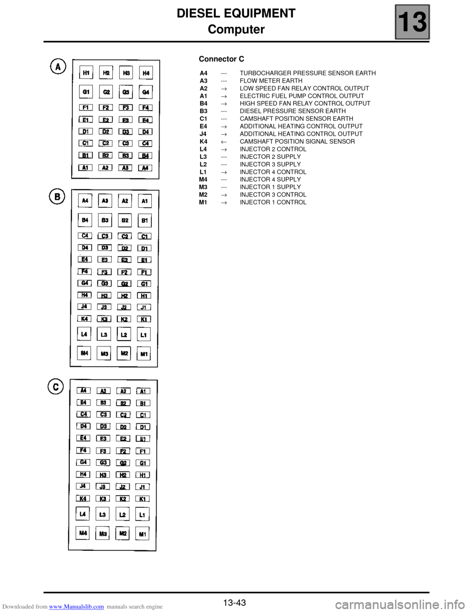
Connector C
A4
A3
A2
A1
B4
B3
C1
E4
J4
K4
L4
L3
L2
L1
M4
M3
M2
M1---
---
→
→
→
---
---
→
→
←
→
---
---
→
---
---
→
→TURBOCHARGER PRESSURE SENSOR EARTH
FLOW METER EARTH
LOW SPEED FAN RELAY CONTROL OUTPUT
ELECTRIC FUEL PUMP CONTROL OUTPUT
HIGH SPEED FAN RELAY CONTROL OUTPUT
DIESEL PRESSURE SENSOR EARTH
CAMSHAFT POSITION SENSOR EARTH
ADDITIONAL HEATING CONTROL OUTPUT
ADDITIONAL HEATING CONTROL OUTPUT
CAMSHAFT POSITION SIGNAL SENSOR
INJECTOR 2 CONTROL
INJECTOR 2 SUPPLY
INJECTOR 3 SUPPLY
INJECTOR 4 CONTROL
INJECTOR 4 SUPPLY
INJECTOR 1 SUPPLY
INJECTOR 3 CONTROL
INJECTOR 1 CONTROL