display RENAULT SCENIC 2006 J84 / 2.G Multimedia Nav 4R User Guide
[x] Cancel search | Manufacturer: RENAULT, Model Year: 2006, Model line: SCENIC, Model: RENAULT SCENIC 2006 J84 / 2.GPages: 86, PDF Size: 0.29 MB
Page 23 of 86
MULTIMEDIA
Fault finding - Interpretation of faults
86C
86C-22
NAV 4R
Program no.: 0000
Vdiag No.: 24
DF027
PRESENT
OR
STOREDNO AUDIO CD CHANGER SIGNALS
1.DEF : No communication with the CD changer
NOTESOrder of priority in the event of more than one fault:
Deal with fault DF001 Computer first, if present or stored.
Conditions for applying fault finding procedures to stored faults:
Apply this fault finding procedure if the fault reappears as present or stored after it has
been cleared and the ignition has been switched off and on again.
Special note:
If the vehicle does not have a CD changer, check the 4R radio navigation computer
configuration (see Configuration and programming).
Apply the following fault finding procedure to vehicles equipped with a CD changer.
Use the Wiring Diagram Technical Note for the vehicle concerned.
Look for any damage to the wiring harness, check the condition and connection of the connectors on
components 261 and 1272.
Manipulate the wiring harness in order to produce a change in the fault status (present → stored).
If the connector is faulty and there is a repair procedure (see Technical Note 6015A, Electrical wiring repair,
Wiring: Precautions for repair), repair the connector, otherwise replace the wiring.
Using the universal bornier, check the insulation, continuity and the absence of interference resistance on
the following connections:
●connection code 34AZ,
●connection code 34BA,
●connection code 34BL,
●connection code 34BC,
●connection code 34BD,
●connection code 34BG,
●connection code 34BH,
●connection code 34BK (only for Scénic),
between components 261 and 1272.
If the connection or connections are faulty and there is a repair procedure (see Technical Note 6015A, Electrical
wiring repair, Wiring: Precautions for repair), repair the wiring, otherwise replace it.
If the fault is still present, contact the Techline.
AFTER REPAIRDeal with any faults displayed by the diagnostic tool.
Clear the faults from the 4R radio navigation computer memory using command RZ001
Fault memory.
NAV4R_V24_DF027
Page 24 of 86
MULTIMEDIA
Fault finding - Interpretation of faults
86C
86C-23
NAV 4R
Program no.: 0000
Vdiag No.: 24
DF030
PRESENT
OR
STOREDGPS AERIAL CIRCUIT
CO : Open circuit
NOTESConditions for applying fault finding procedures to stored faults:
Apply this fault finding procedure if the fault reappears as present or stored after it has
been cleared and the ignition has been switched off and on again.
Use the Wiring Diagram Technical Note for the vehicle concerned.
Check the condition and connection of the GPS coaxial connector on components 261 (Trafic: 662) and 886
(and 1551 for Laguna and Mégane cabriolet) (bent pins, bad contacts, etc.).
Carefully manipulate the wiring harness in order to produce a change in fault status (present → stored).
If the connector is faulty and there is a repair procedure (see Technical Note 6015A, Electrical wiring repair,
Wiring: Precautions for repair), repair the connector, otherwise replace the wiring.
Using the universal bornier, check the insulation, continuity and the absence of interference resistance on
the following connections:
Mégane cabriolet:
●connection code TB13,
●connection code 34AN,
between components 261 and 886;
●connection code 46CB,
●connection code TB15,
between components 886 and 1551.
Mégane hatch and Scénic:
●connection code TB13,
●connection code 34AN,
●connection code 46CB,
●connection code TB15,
between components 261 and 886.
AFTER REPAIRDeal with any faults displayed by the diagnostic tool.
Clear the faults from the 4R radio navigation computer memory using command RZ001
Fault memory.
Check the number of satellites received from outside, with the system switched on for
10 minutes, followed by a new check with the diagnostic tool.
NAV4R_V24_DF030
Page 25 of 86
MULTIMEDIA
Fault finding - Interpretation of faults
86C
86C-24
NAV 4R
Program no.: 0000
Vdiag No.: 24
DF030
CONTINUED 1
Laguna:
●connection code TB13,
●connection code 34AN,
between components 261 and 886.
●connection code 46CB,
●connection code TB15,
between components 261 and 1551.
Trafic:
●connection code TB13,
●connection code 34AN,
●connection code 46CB,
●connection code TB15,
between components 662 and 886.
Master:
●connection code TB13,
●connection code 34AN,
●connection code 46CB,
●connection code TB15,
between components 261 and 886.
If the connection or connections are faulty and there is a repair procedure (see Technical Note 6015A, Electrical
wiring repair, Wiring: Precautions for repair), repair the wiring, otherwise replace it.
AFTER REPAIRDeal with any faults displayed by the diagnostic tool.
Clear the faults from the 4R radio navigation computer memory using command RZ001
Fault memory.
Check the number of satellites received from outside, with the system switched on for
10 minutes, followed by a new check with the diagnostic tool.
Page 26 of 86
MULTIMEDIA
Fault finding - Interpretation of faults
86C
86C-25
NAV 4R
Program no.: 0000
Vdiag No.: 24
DF030
CONTINUED 2
If the connections are correct, replace component 1551 or 886.
Mégane II ph2
(see MR 364 mechanical, 83C On-board telematics system, Aerial: Removal - Refitting)
Laguna II ph2
(see MR 395 mechanical, 83C On-board telematics system, Aerial: Removal - Refitting)
Scénic II ph2
(see MR 370 mechanical, 83C On-board telematics system, Aerial: Removal - Refitting)
Trafic II ph1 and ph2
(see MR 408 mechanical, 83C On-board telematics system, Aerial: Removal - Refitting)
Master ph2 and ph3
(see MR 377 mechanical, 83C On-board telematics system, Aerial: Removal - Refitting)
Master propulsion ph2
(see Technical Note 3818A, 83C On-board telematics system, Navigation aerial: Removal - Refitting).
Look for any damage to the coaxial cable.
If the fault is still present, contact the Techline.
AFTER REPAIRDeal with any faults displayed by the diagnostic tool.
Clear the faults from the 4R radio navigation computer memory using command RZ001
Fault memory.
Check the number of satellites received from outside, with the system switched on for
10 minutes, followed by a new check with the diagnostic tool.
Page 27 of 86
MULTIMEDIA
Fault finding - Interpretation of faults
86C
86C-26
NAV 4R
Program no.: 0000
Vdiag No.: 24
DF032
PRESENT
OR
STOREDDISPLAY SUPPLY
CO.1 : Short circuit or open circuit to + 12 V
NOTESConditions for applying fault finding procedures to stored faults:
Apply this fault finding procedure if the fault reappears as present or stored after it has
been cleared and the ignition has been switched off and on again.
Special note:
Run command AC021 Display test. Three colours are displayed on the screen: Red,
green and blue, and a black mosaic on a white background. If this is not displayed,
apply the fault finding procedure detailed below.
Use the Wiring Diagram Technical Note for the vehicle concerned.
Check the condition and connection of the video connector on components 261 (Trafic: 662) and 1127 (bent
pins, bad contacts, etc.).
If the connector is faulty and there is a repair procedure (see Technical Note 6015A, Electrical wiring repair,
Wiring: Precautions for repair), repair the connector, otherwise replace the wiring.
Using the universal bornier, check the insulation, continuity and the absence of interference resistance on
the following connections:
●connection code 46M,
●connection code 46N,
●connection code 46BG,
●connection code 46BH,
●connection code 46BK,
between components 261 (Trafic: 662) and 1127.
If the connection or connections are faulty and there is a repair procedure (see Technical Note 6015A, Electrical
wiring repair, Wiring: Precautions for repair), repair the wiring, otherwise replace it.
Check for + 12 V on connections 46M and 46N of the connector of component 1127.
Also check for earth on connections 46BG, 46BH and 46BK of the connector of component 1127.
If the connection or connections are faulty and there is a repair procedure (see Technical Note 6015A, Electrical
wiring repair, Wiring: Precautions for repair), repair the wiring, otherwise replace it.
If the fault is still present, contact the Techline.
AFTER REPAIRCheck that the screen is operating correctly using command AC021 Display test.
Deal with any faults displayed by the diagnostic tool.
Clear the faults from the 4R radio navigation computer memory using command RZ001
Fault memory.
NAV4R_V24_DF032
Page 28 of 86
MULTIMEDIA
Fault finding - Interpretation of faults
86C
86C-27
NAV 4R
Program no.: 0000
Vdiag No.: 24
DF034
PRESENT
CD READER
1.DEF : CD unreadable
NOTESSpecial note:
The system enables:
–CD-ROM maps to be displayed,
–the user to listen to commercial audio CDs, CDs burned independently, CDs
containing MP3 files (optional). The CDs are read by the 4R unit's CD player or by
the optional 6-CD changer.
Check that the CD is not scratched.
For a CD-ROM card, change the CD.
For all other types of CD, check that the CD format is compatible with the system.
If the fault is still present, contact the Techline.
AFTER REPAIRDeal with any faults displayed by the diagnostic tool.
Clear the faults from the 4R radio navigation computer memory using command RZ001
Fault memory.
NAV4R_V24_DF034P
Page 29 of 86
MULTIMEDIA
Fault finding - Interpretation of faults
86C
86C-28
NAV 4R
Program no.: 0000
Vdiag No.: 24
DF035
PRESENT
OR
STOREDCOMPUTER/FOLD-OUT UNIT CONNECTION
CO.1 : Short circuit or open circuit to + 12 V
NOTESConditions for applying fault finding procedures to stored faults:
Apply this fault finding procedure if the fault reappears as present or stored after it has
been cleared and the ignition has been switched off and on again.
Special note:
If the vehicle does not have a fold-out unit, check the 4R radio navigation computer
configuration (see Configuration and programming).
The screen does not deploy or there is no display on the instrument panel.
Apply the following fault finding procedure only if the vehicle is equipped with a fold-out
unit and a dot matrix display on the instrument panel (top of the range Mégane II
phase 2).
Use the Wiring Diagrams Technical Note for the Mégane II.
Check the condition and connection of the connectors of components 261, 1303 and 247 (bent pins, bad
contacts, etc.).
If the connector is faulty and there is a repair procedure (see Technical Note 6015A, Electrical wiring repair,
Wiring: Precautions for repair), repair the connector, otherwise replace the wiring.
Manipulate the wiring harness in order to produce a change in the fault status (present → stored).
Check the insulation, continuity and the absence of interference resistance on connection 34GG between
components 261 and 1303.
If the connection is faulty and there is a repair procedure (see Technical Note 6015A, Electrical wiring repair,
Wiring: Precautions for repair), repair the wiring, otherwise replace it.
Check the insulation, continuity and the absence of interference resistance on connection 34GD between
components 247 and 1303.
If the connection is faulty and there is a repair procedure (see Technical Note 6015A, Electrical wiring repair,
Wiring: Precautions for repair), repair the wiring, otherwise replace it.
If the fault is still present, contact the Techline.
AFTER REPAIRDeal with any faults displayed by the diagnostic tool.
Clear the faults from the 4R radio navigation computer memory using command RZ001
Fault memory.
NAV4R_V24_DF035
Page 30 of 86
MULTIMEDIA
Fault finding - Conformity check
86C
86C-29
NAV 4R
Program no.: 0000
Vdiag No.: 24
Fault finding - Conformity check
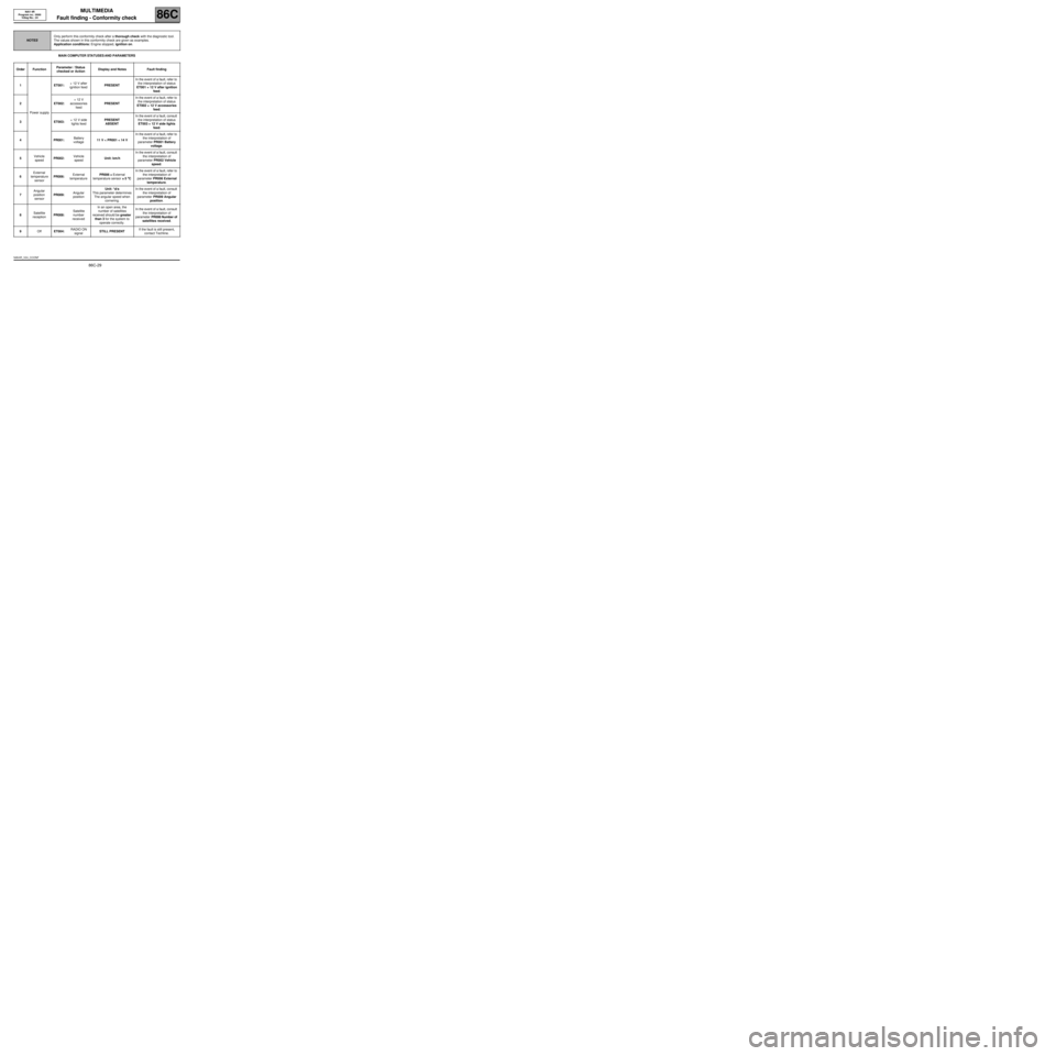
MAIN COMPUTER STATUSES AND PARAMETERS
NOTESOnly perform this conformity check after a thorough check with the diagnostic tool.
The values shown in this conformity check are given as examples.
Application conditions: Engine stopped, ignition on.
Order FunctionParameter / Status
checked or ActionDisplay and Notes Fault finding
1
Power supplyET001:+ 12 V after
ignition feedPRESENTIn the event of a fault, refer to
the interpretation of status
ET001 + 12 V after ignition
feed.
2ET002:+ 12 V
accessories
feedPRESENTIn the event of a fault, refer to
the interpretation of status
ET002 + 12 V accessories
feed.
3ET003:+ 12 V side
lights feedPRESENT
ABSENTIn the event of a fault, consult
the interpretation of status
ET003 + 12 V side lights
feed.
4PR001:Battery
voltage11 V < PR001 < 14 VIn the event of a fault, refer to
the interpretation of
parameter PR001 Battery
voltage.
5Vehicle
speedPR002:Vehicle
speedUnit: km/hIn the event of a fault, consult
the interpretation of
parameter PR002 Vehicle
speed.
6External
temperature
sensorPR006:External
temperaturePR006 = External
temperature sensor ±± ± ±
5 °° ° °
CIn the event of a fault, refer to
the interpretation of
parameter PR006 External
temperature.
7Angular
position
sensorPR009:Angular
positionUnit: *d/s
This parameter determines
The angular speed when
cornering.In the event of a fault, consult
the interpretation of
parameter PR009 Angular
position.
8Satellite
receptionPR008:Satellite
number
receivedIn an open area, the
number of satellites
received should be greater
than 3 for the system to
operate correctly.In the event of a fault, consult
the interpretation of
parameter PR008 Number of
satellites received.
9OffET004:RADIO ON
signalSTILL PRESENTIf the fault is still present,
contact Techline.
NAV4R_V24_CCONF
Page 31 of 86
MULTIMEDIA
Fault finding - Conformity check
86C
86C-30
NAV 4R
Program no.: 0000
Vdiag No.: 24
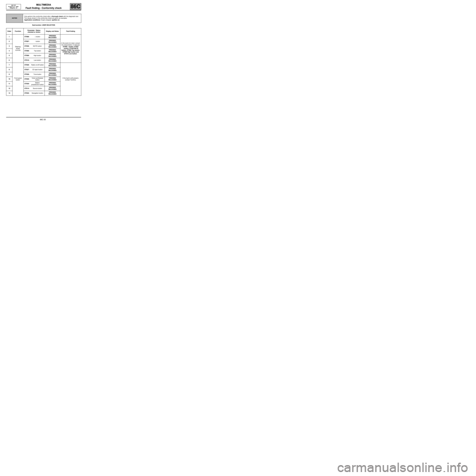
Sub-function: USER SELECTION
NOTESOnly perform this conformity check after a thorough check with the diagnostic tool.
The values shown in this conformity check are given as examples.
Application conditions: Engine stopped, ignition on.
Order FunctionParameter / Status
checked or ActionDisplay and Notes Fault finding
1
Steering
wheel
controlsET006:+ buttonPRESSED
RELEASED
In the event of a fault, consult
the interpretation of statuses
ET006 + button, ET007
- button, ET036 MUTE
button, ET008 Top button,
ET009 High button and
ET010 Low button. 2ET007:- buttonPRESSED
RELEASED
3ET036:MUTE buttonPRESSED
RELEASED
4ET008:Top buttonPRESSED
RELEASED
5ET009:High buttonPRESSED
RELEASED
6ET010:Low buttonPRESSED
RELEASED
7
Front panel
buttonET026:Radio on/off buttonPRESSED
RELEASED
If the fault is still present,
contact Techline. 8ET027:CD eject buttonPRESSED
RELEASED
9ET028:Tone buttonPRESSED
RELEASED
10 ET029:Voice synthesiser
buttonPRESSED
RELEASED
11 ET030:Station
preselection buttonPRESSED
RELEASED
12 ET014:Source buttonPRESSED
RELEASED
13 ET032:Navigation buttonPRESSED
RELEASED
Page 32 of 86
MULTIMEDIA
Fault finding - Conformity check
86C
86C-31
NAV 4R
Program no.: 0000
Vdiag No.: 24
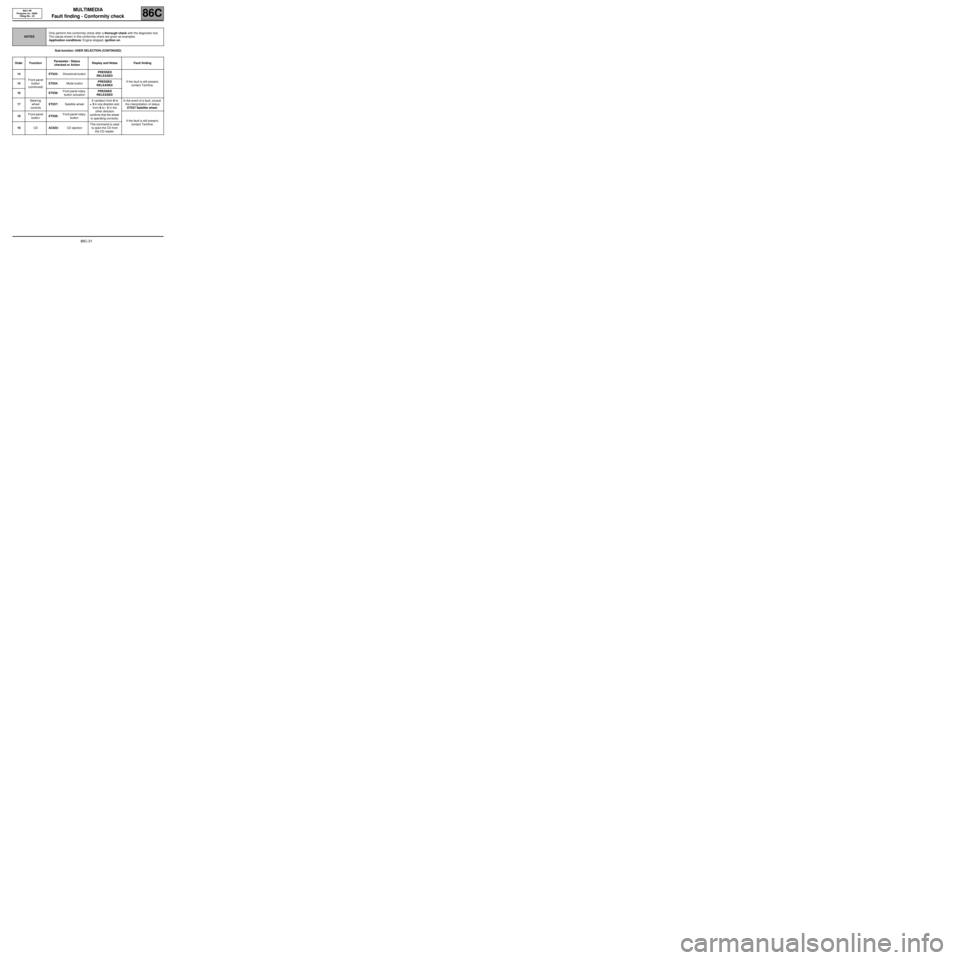
Sub-function: USER SELECTION (CONTINUED)
NOTESOnly perform this conformity check after a thorough check with the diagnostic tool.
The values shown in this conformity check are given as examples.
Application conditions: Engine stopped, ignition on.
Order FunctionParameter / Status
checked or ActionDisplay and Notes Fault finding
14
Front panel
button
(continued)ET033:Directional buttonPRESSED
RELEASED
If the fault is still present,
contact Techline. 15 ET034:Mode buttonPRESSED
RELEASED
16 ET039:Front panel rotary
button actuationPRESSED
RELEASED
17Steering
wheel
controlsET037:Satellite wheelA variation from 0 to
+ 3 in one direction and
from 0 to - 3 in the
other direction
confirms that the wheel
is operating correctly.In the event of a fault, consult
the interpretation of status
ET037 Satellite wheel.
18Front panel
buttonET038:Front panel rotary
button
If the fault is still present,
contact Techline.
19CDAC022:CD ejectionThis command is used
to eject the CD from
the CD reader.