fuses RENAULT SCENIC 2006 J84 / 2.G Multimedia Nav 4R Workshop Manual
[x] Cancel search | Manufacturer: RENAULT, Model Year: 2006, Model line: SCENIC, Model: RENAULT SCENIC 2006 J84 / 2.GPages: 86, PDF Size: 0.29 MB
Page 5 of 86
MULTIMEDIA
Fault finding - Introduction
86C
86C-4
NAV 4R
Program no.: 0000
Vdiag No.: 24
4. FAULT FINDING PROCEDURE (continued)
Wiring check
Fault finding problems
Disconnecting the connectors and/or manipulating the wiring harness may temporarily remove the cause of a fault.
Electrical measurements of voltage, resistance and insulation are generally correct, especially if the fault is not
present when the analysis is made (stored fault).
Visual inspection
Look for damage under the bonnet and in the passenger compartment.
Carefully check the fuses, insulation and wiring harness routing.
Look for signs of oxidation.
Tactile inspection
While manipulating the wiring harness, use the diagnostic tool to note any change in fault status from stored to
present.
Check that the connectors are properly locked.
Apply light pressure to the connectors.
Twist the wiring harness.
If there is a change in status, try to locate the source of the fault.
Inspection of each component
Disconnect the connectors and check the appearance of the clips and tabs, as well as the crimping (no crimping on
the insulating section).
Make sure that the clips and tabs are properly locked in the holes.
Check that no clips or tabs have been dislodged during connection.
Check the clip contact pressure using an appropriate model of tab.
Resistance check
Check the continuity of entire lines, then section by section.
Look for a short circuit to earth, to + 12 V or to another wire.
If a fault is detected, repair or replace the wiring harness.
Page 8 of 86
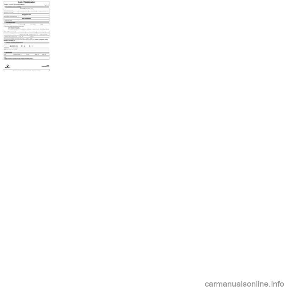
To check the GPS reception status, follow the procedure below:
Position the vehicle in an open area
Wait for 15 minutes with the ignition on
In the navigation system, go to Fault finding: Navigation →→ → →
Configuration →→ → →
System information →→ → →
Fault finding→→ → →
GPS status
Vehicle speed signal fault finding, change of value when driving? YES NO
To run this fault finding procedure on the navigation system, from the following fault finding menu: Navigation →→ → →
Configuration →→ → →
System
information →→ → →
Fault finding →→ → →
I/O
Vehicle restart
after a cut-off of > 1 min: OUT NO
after a cut-off of <1 min: OUT NO
By action on: .................................................................................................................................................................................................
.................................................................................................................................................................................................
The fault disappears by itself (state time): .............................................................................................................. .............................................
Other (give as much detail as possible): ..............................................................................................................................................................
.............................................................................................. ...............................................................
FAULT FINDING LOG
System: Carminat Advanced NavigationPage 2 of 2
â—ŹDocumentation used in fault finding
Fault finding procedure used
Type of diagnostic manual:
Workshop Repair Manual Technical Note Assisted fault finding
Fault finding manual number
Wiring diagram used
Wiring Diagram Technical Note Number:
Other documentation
Title and/or part number:
â—Ź
Workshop fault finding
GPS reception status:
COM.ERROR Search Sat ≥ 3 sat
Status red LED computer front panel:
Permanently off Permanently flashing Permanently lit
Carminat computer (CD-ROM reader):
Impossible to insert CD Impossible to eject CD Refuses to read CD
Cartographic map CD scratched or dirty:
YES NO
â—Ź
Conditions under which fault disappears
â—ŹParts returned
Parts: Navigation computer CCU Keypad Screen
Note:
Complete and submit a fault finding log for each component removed and returned.
FD98
Fault finding log
page to print or photocopy - page to print or photocopy - page to print or photocopy
Page 36 of 86
MULTIMEDIA
Fault finding - Interpretation of statuses
86C
86C-35
NAV 4R
Program no.: 0000
Vdiag No.: 24
Fault finding - Interpretation of statuses
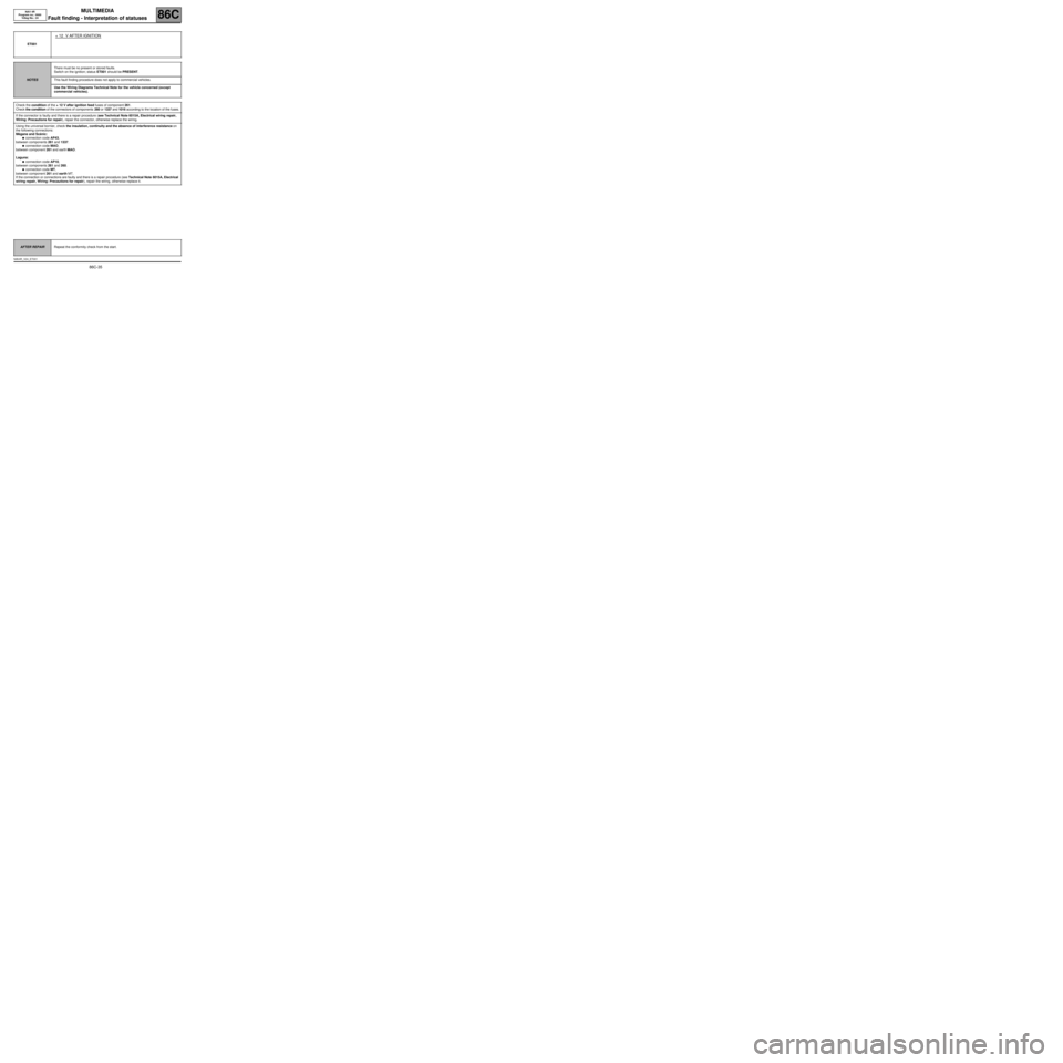
ET001
+ 12 V AFTER IGNITION
NOTESThere must be no present or stored faults.
Switch on the ignition; status ET001 should be PRESENT.
This fault finding procedure does not apply to commercial vehicles.
Use the Wiring Diagrams Technical Note for the vehicle concerned (except
commercial vehicles).
Check the condition of the + 12 V after ignition feed fuses of component 261.
Check the condition of the connectors of components 260 or 1337 and 1016 according to the location of the fuses.
If the connector is faulty and there is a repair procedure (see Technical Note 6015A, Electrical wiring repair,
Wiring: Precautions for repair), repair the connector, otherwise replace the wiring.
Using the universal bornier, check the insulation, continuity and the absence of interference resistance on
the following connections:
Mégane and Scénic:
â—Źconnection code AP43,
between components 261 and 1337.
â—Źconnection code MAO,
between component 261 and earth MAO.
Laguna:
â—Źconnection code AP10,
between components 261 and 260.
â—Źconnection code MT,
between component 261 and earth MT.
If the connection or connections are faulty and there is a repair procedure (see Technical Note 6015A, Electrical
wiring repair, Wiring: Precautions for repair), repair the wiring, otherwise replace it.
AFTER REPAIRRepeat the conformity check from the start.
NAV4R_V24_ET001
Page 37 of 86
MULTIMEDIA
Fault finding - Interpretation of statuses
86C
86C-36
NAV 4R
Program no.: 0000
Vdiag No.: 24
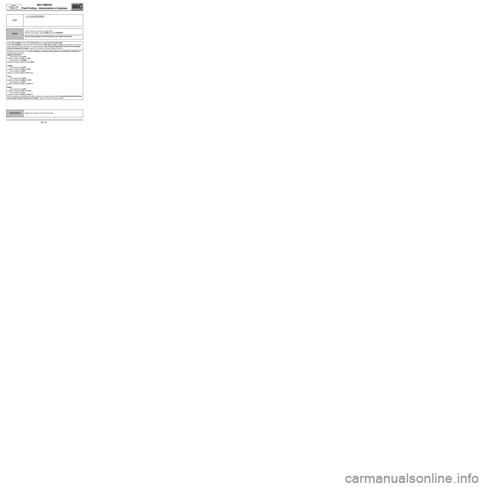
ET002
+ 12 V ACCESSORIES
NOTESThere must be no present or stored faults.
Switch on the ignition, status ET002 should be PRESENT.
Use the Wiring Diagram Technical Note for the vehicle concerned.
Check the condition of the + 12 V ACC feed fuse of component 261 (Trafic: 662).
Check the condition of the connectors of components 260, 1016 or 1337 according to the location of the fuses.
If the connector is faulty and there is a repair procedure (see Technical Note 6015A, Electrical wiring repair,
Wiring: Precautions for repair), repair the connector, otherwise replace the wiring.
Using the universal bornier, check the insulation, continuity and the absence of interference resistance on
the following connections:
Mégane and Scénic:
â—Źconnection code SP2,
between components 261 and 260.
â—Źconnection code MAO,
between component 261 and earth MAO.
Laguna:
â—Źconnection code SP2,
between components 261 and 260.
â—Źconnection code MT,
between component 261 and MT earth.
Trafic:
â—Źconnection code SP2,
between components 662 and 1016.
â—Źconnection code MT,
between component 662 and earth MT.
Master:
â—Źconnection code SP2,
between components 261 and 1016.
â—Źconnection code NL,
between component 662 and earth NL.
If the connection or connections are faulty and there is a repair procedure (see Technical Note 6015A, Electrical
wiring repair, Wiring: Precautions for repair), repair the wiring, otherwise replace it.
AFTER REPAIRRepeat the conformity check from the start.
Page 64 of 86
MULTIMEDIA
Diagnostic - Fault finding chart86C
86C-63
NAV 4R
Program no.: 0000
Vdiag No.: 24
Diagnostic - Fault finding chart
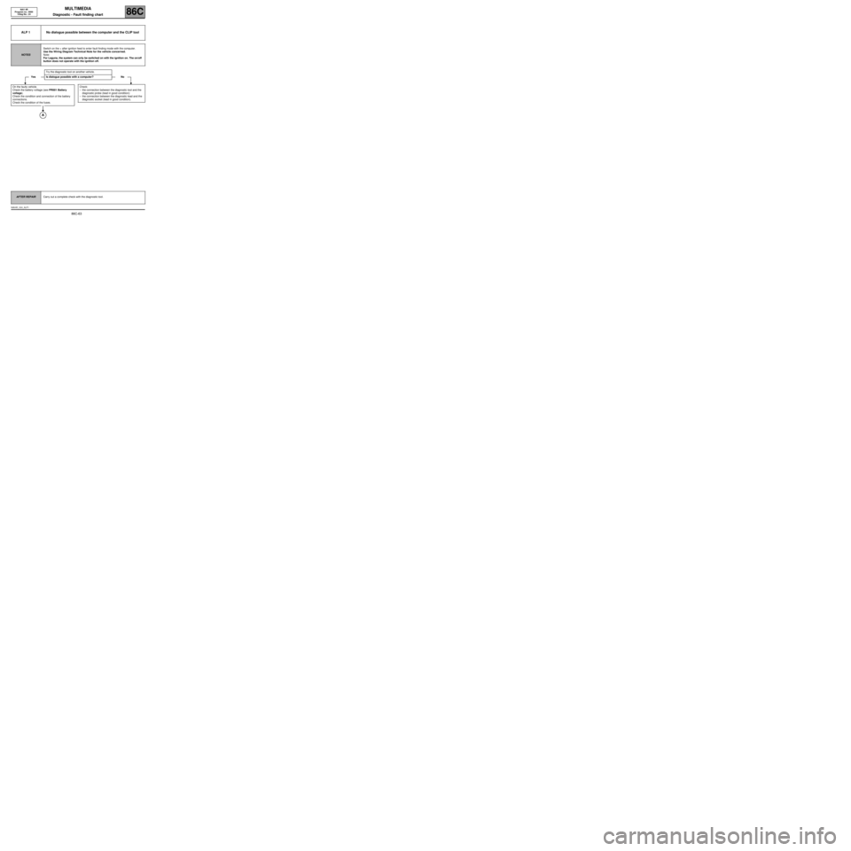
ALP 1 No dialogue possible between the computer and the CLIP tool
NOTESSwitch on the + after ignition feed to enter fault finding mode with the computer.
Use the Wiring Diagram Technical Note for the vehicle concerned.
Note:
For Laguna, the system can only be switched on with the ignition on. The on/off
button does not operate with the ignition off.
Try the diagnostic tool on another vehicle.
Yes Is dialogue possible with a computer? No
On the faulty vehicle.
Check the battery voltage (see PR001 Battery
voltage).
Check the condition and connection of the battery
connections.
Check the condition of the fuses.
Check:
–the connection between the diagnostic tool and the
diagnostic probe (lead in good condition):
–the connection between the diagnostic lead and the
diagnostic socket (lead in good condition).
AFTER REPAIRCarry out a complete check with the diagnostic tool.
NAV4R_V24_ALP1