display RENAULT SCENIC 2006 J84 / 2.G Tyre Pressure Monitoring Workshop Manual
[x] Cancel search | Manufacturer: RENAULT, Model Year: 2006, Model line: SCENIC, Model: RENAULT SCENIC 2006 J84 / 2.GPages: 37, PDF Size: 0.15 MB
Page 4 of 37
TYRE PRESSURE MONITOR
Fault finding - Introduction
35B
35B-3
UCH
Program no.: 350 and higher
Vdiag No: 48-4C-4D-4F-50
To cut off + after ignition, proceed as follows:
–Disconnect the diagnostic tool.
–Press the Start button twice briefly (less than 3 seconds),
–See that the + after ignition feed has been cut off by checking that the computer warning lights on the
instrument panel have gone out.
Faults
The current status of faults must be considered when the diagnostic tool is used following switching to + after
ignition (with no action on the system components).
For a present fault, handle the fault according to the procedure listed in the section on Interpretation of faults in
Workshop Repair Manual 372 Section 87B Passenger compartment connection unit.
There is no stored fault on the tyre pressure monitor.
Conformity check
The aim of the conformity check is to check statuses and parameters that do not produce a fault display on the
diagnostic tool when they are inconsistent. Therefore, this stage is used to:
–carry out fault finding on faults that do not have a fault display, and which may correspond to a customer
complaint.
–check that the system is operating correctly and that there is no risk of a fault recurring after repairs.
This section features the fault finding procedure for statuses and parameters, and the conditions for checking them.
If a status is not operating normally or a parameter is outside permitted tolerance values, you should consult the
corresponding fault finding page.
Customer complaints - Fault finding chart
If the check using the diagnostic tool is satisfactory but the customer complaint is still present, the fault should be
treated as a customer complaint.
A summary of the overall procedure to follow is provided on the following page
in the form of a flow chart.
Edition 4
Page 8 of 37
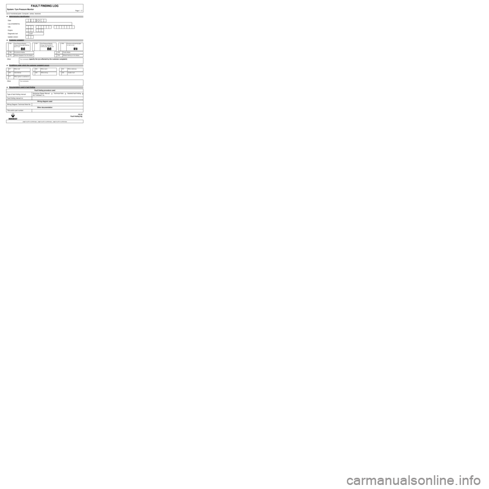
List of monitored parts: Computer, valves, receivers
FAULT FINDING LOG
System: Tyre Pressure MonitorPage 1 / 2
●Administrative identification
Date 2 0
Log completed by
VIN
Engine
Diagnostic tool CLIP
Update version
●Customer complaint
1794 Tyre Pressure Monitor
orange warning light flashing:
text or icon
1797 Tyre Pressure Monitor
orange warning light lit
continuously: text or icon
1795 Puncture red warning light
lit: text or icon
1798 No pressure display 1796 Faulty display
1793 Wheels disappear from the display 1792 Wheels flashing on the display
OtherYour comments: (specify the tyre affected by the customer complaint):
●Conditions under which the customer complaint occurs
001 When cold 002 When warm 003 When stationary
004 Intermittently 005 While driving 009 Sudden fault
011 When ignition is switched on
OtherYour comments:
●
Documentation used in fault finding
Fault finding procedure used
Type of fault finding manual:Workshop Repair Manual: Technical Note Assisted fault finding
ALP followed: no...
Fault finding manual no:
Wiring diagram used
Wiring Diagram Technical Note No:
Other documentation
Title and/or part number:
FD 23
Fault finding log
page to print or photocopy - page to print or photocopy - page to print or photocopy
Page 10 of 37
TYRE PRESSURE MONITOR
Fault finding - System operation
35B
UCH
Program no.: 350 and higher
Vdiag No: 48-4C-4D-4F-50TYRE PRESSURE MONITOR
Fault finding - System operation
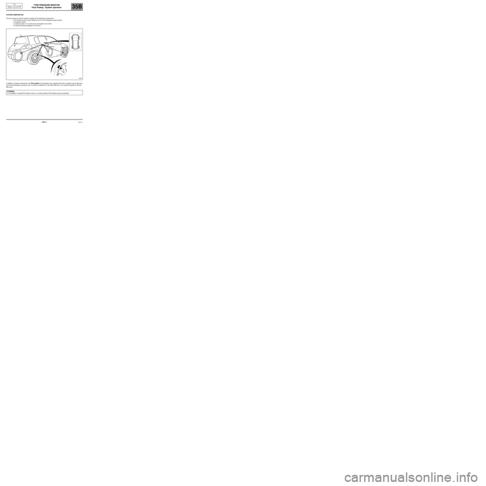
SYSTEM COMPOSITION
The tyre pressure monitor system consists of the following components:
–four sensors (one on each wheel but not on the emergency spare wheel)
–a computer (UCH)
–a receiver aerial (17-cm bare wire connected to the UCH)
–an instrument panel display for the driver
In addition to these components, the PAX system is comprised of four special tyres with a support ring to allow flat
tyre driving following a puncture over a maximum distance of 120 miles (200 km), at a maximum speed of 48 mph
(80 km/h).
WARNING
It is forbidden to install PAX System tyres on a vehicle without PAX System tyres as standard.
Edition 435B-9
Page 11 of 37
TYRE PRESSURE MONITOR
Fault finding - System operation
35B
UCH
Program no.: 350 and higher
Vdiag No: 48-4C-4D-4F-50
System operation:
–The valves are activated after driving at a speed greater than 12 mph (20 km/h).
–During driving, the valves emit signals every minute.
–The valves remain active for 15 minutes after the vehicle stops, then switch to standby mode.
–In standby mode, the valves emit signals only if they detect a pressure difference between two successive
measurements greater than 68 mbar or if the pressure difference since last emitting is greater than 68 mbar (due
to tyre cooling).
–The tyres are considered to be cold when the vehicle speed has been zero for 1h 45 min.
–The minimum time for detection of a leak is approximately 15 minutes.
–The message Pressure unsuitable for the speed is activated only if the vehicle travels at more than 102 mph
(170 km/h) (as an indication) for 3 minutes and the pressure on at least one of the tyres is 400 mbar less than the
recommended pressure at low speed. This message is inactive if the tyres are inflated to motorway pressure,
irrespective of the vehicle speed.
–Alert thresholds:
–over-inflated while cold =recommended pressure + 700 mbar
–over-inflated while warm = recommended pressure + 850 mbar
–under-inflated = recommended pressure - 400 mbar
–very under-inflated = recommended pressure - 600 mbar
–imbalance = difference in pressure between the left-hand and right-hand wheels on the same axle greater
than 500 mbar
–Tyre pressure monitor information messages for the driver:
–"PUNCTURE: CHANGE TYRE" + STOP warning light + highlighting of the wheel concerned on the
instrument panel display + buzzer.
–"ADJUST TYRE PRESSURE" + highlighting of the wheel concerned on the instrument panel.
–"INFLATE TYRES MOTORWAY" + highlighting of all four wheels on the instrument panel.
–"TYRE SENSOR INOPERATIVE" + clearing of the wheel concerned.
–"ELECTRONIC FAULT" + "Service" warning light + the wheels concerned disappear from the
instrument panel.
–Tyre pressure monitor information messages for a puncture with the PAX System:
–"PUNCTURE: REPAIR TYRE" + highlighting of the wheel concerned on the instrument panel.
–"PUNCTURE: SLOW DOWN" + buzzer (if vehicle speed > 48 mph (80 km/h)).
–"DRIVING WITH FLAT: X MILES REMAINING" (X decreases from 120 miles (200 km) to 0) + STOP
warning light when X = 0 + highlighting of the wheel concerned on the instrument panel.
⇒
No instrument panel display of tyre pressure on the SCENIC II.
Edition 435B-10
Page 15 of 37
TYRE PRESSURE MONITOR
Fault finding - Configurations and programming
35B
UCH
Program no.: 350 and higher
Vdiag No: 48-4C-4D-4F-50TYRE PRESSURE MONITOR
Fault finding - Configurations and programming
SC002:
PROGRAMMING THE FOUR VALVE CODES
IMPORTANT
Any repairs that involve replacement of a wheel sensor require knowledge of the recommendations
defined in Workshop Repair Manual 371 section 35.
–Inflate the four tyres to 3.8 bar.
–Using the diagnostic tool, establish dialogue with the UCH.
–Select the Repair mode menu
–Select the Programming menu
–Select line SC002 Programming the four valve codes under the Tyres function.
Display of stored codes and recognised valve set.
–Select the Valve set selection menu, then Summer or Winter.
–Confirm to obtain the table "valve programming conditions".
–Confirm by selecting next, which brings up the search for valve code menu.
–Excite each valve by holding the valve exciter on the tyre, just under the valve in question.
–Start with the front left-hand wheel.
–Wait for the new code to appear on the screen before moving on to the next valve.
–Program the codes in the following order:
Front left-hand Front right-hand Rear right-hand Rear left-hand
–Click on the "Confirm" button to transmit the codes to the UCH.
–Inflate the tyres to the recommended pressures.
–Carry out a road test: speed > 12 mph (20 km/h) for 10 minutes.
–Make sure no message appears on the instrument panel.
IMPORTANT
When swapping wheels over, reprogram the UCH for the new valve positions using the diagnostic tool and
programming the valve codes.
Then replace the colour rings in the locations noted on the label on the driver's door.
Edition 435B-14
Page 16 of 37
TYRE PRESSURE MONITOR
Fault finding - Configurations and programming
35B
UCH
Program no.: 350 and higher
Vdiag No: 48-4C-4D-4F-50
SC001:
READING VALVE SETS AND STORED CODES
–Select the Repair mode menu
–Select the Programming menu
–Select line SC001 Read valve set and stored codes in the Tyres function.
VP005
ENTERING RECOMMENDED PRESSURES
To enter the recommended pressures correctly, use the values specified by the manufacturer and found in the
Workshop Repair Manual or driver's handbook for the vehicle with the tyres installed on the vehicle, or
indicated on the label on the driver's door.
–Select the repair mode menu.
–Select the other parameters menu.
–Select line VP005 Enter recommended pressures.
–Program the vehicle type: MPV or other.
–Enter the recommended pressures at the keyboard.
–Confirm the pressures.
–Click on "Finish" to end the procedure.
Check the recommended pressures in memory:
–Select the Statuses/Parameters menu.
–Select the Tyre management menu.
–Read parameters PR009 to PR012.
–If there is a fault, repeat the operation from the beginning.
IMPORTANT
If the recommended pressure format is not correct or if the pressure entered is outside the permitted tolerance
values in relation to the type of vehicle selected, the following error message will be displayed: "Procedure failed:
incorrect pressure format or value outside authorised range".
Edition 435B-15
Page 17 of 37
TYRE PRESSURE MONITOR
Fault finding - Configurations and programming
35B
UCH
Program no.: 350 and higher
Vdiag No: 48-4C-4D-4F-50
CF023:
TYRE PRESSURE MONITOR FUNCTION
(in programming command SC008 UCH type)
WRITING THE CONFIGURATION WITH OR WITHOUT TYRE PRESSURE MONITOR:
–Select the repair mode menu.
–Select the Programming menu
Select line SC008 UCH type, then the line CF023 Tyre Pressure Monitor function then with or without
Confirm the selection.
Check that the configuration has been stored correctly.
IMPORTANT
CONFIGURATION INCONSISTENCY BETWEEN THE INSTRUMENT PANEL AND UCH
1
st case: If the instrument panel detects the tyre pressure monitor system programmed in the UCH but
not in its own configuration. The message ELECTRONIC FAULT appears, the four wheels
disappear on the instrument panel display, and the Service warning light comes on.
2
nd case: The instrument panel detects that the Tyre pressure monitor is programmed in its own
configuration but the UCH fails to respond to any requests from the instrument panel (not
configured in UCH). The message TYRE SENSOR INOPERATIVE will appear, the four wheels
will disappear from the instrument panel display and the Service warning light will come on.
Edition 435B-16
Page 19 of 37
TYRE PRESSURE MONITOR
Fault finding - Conformity check
35B
UCH
Program no.: 350 and higher
Vdiag No: 48-4C-4D-4F-50TYRE PRESSURE MONITOR
Fault finding - Conformity check
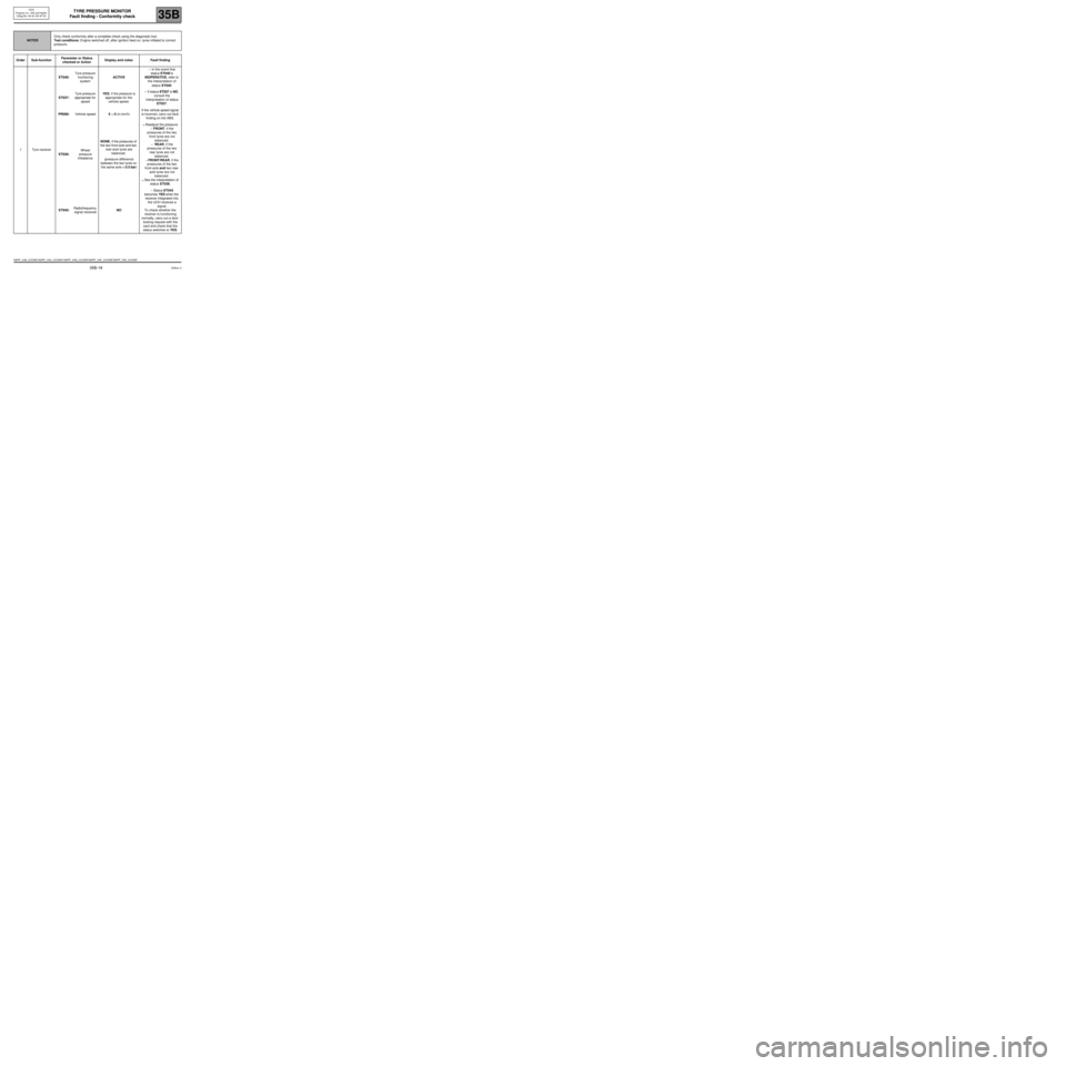
NOTESOnly check conformity after a complete check using the diagnostic tool.
Test conditions: Engine switched off, after ignition feed on, tyres inflated to correct
pressure.
Order Sub-functionParameter or Status
checked or ActionDisplay and notes Fault finding
1Tyre receiverET040:Tyre pressure
monitoring
systemACTIVE– In the event that
status ET040 is
INOPERATIVE, refer to
the interpretation of
status ET040.
ET037:Tyre pressure
appropriate for
speedYES, if the pressure is
appropriate for the
vehicle speed.– If status ET037 is NO,
consult the
interpretation of status
ET037.
PR008:Vehicle speedX = 0 (in km/h)If the vehicle speed signal
is incorrect, carry out fault
finding on the ABS.
ET036:Wheel
pressure
imbalanceNONE, if the pressures of
the two front-axle and two
rear-axle tyres are
balanced.
(pressure difference
between the two tyres on
the same axle < 0.5 bar)
⇒ Readjust the pressure.
– FRONT, if the
pressures of the two
front tyres are not
balanced.
– REAR, if the
pressures of the two
rear tyres are not
balanced.
– FRONT/REAR, if the
pressures of the two
front-axle and two rear-
axle tyres are not
balanced.
⇒ See the interpretation of
status ET036.
ET045:Radiofrequency
signal receivedNO– Status ET045
becomes YES when the
receiver integrated into
the UCH receives a
signal.
To check whether the
receiver is functioning
normally, carry out a door
locking request with the
card and check that the
status switches to YES.
SSPP_V48_CCONF/SSPP_V4C_CCONF/ SSPP_V4D_CCONF/SSPP_V4F_CCONF/SSPP_V50_CCONF
Edition 4
35B-18
Page 20 of 37
TYRE PRESSURE MONITOR
Fault finding - Conformity check
35B
UCH
Program no.: 350 and higher
Vdiag No: 48-4C-4D-4F-50
NOTESOnly check conformity after a complete check using the diagnostic tool.
Test conditions: Engine switched off, after ignition feed on, tyres inflated to correct
pressure.
Order Sub-functionParameter or Status
checked or ActionDisplay and notes Fault finding
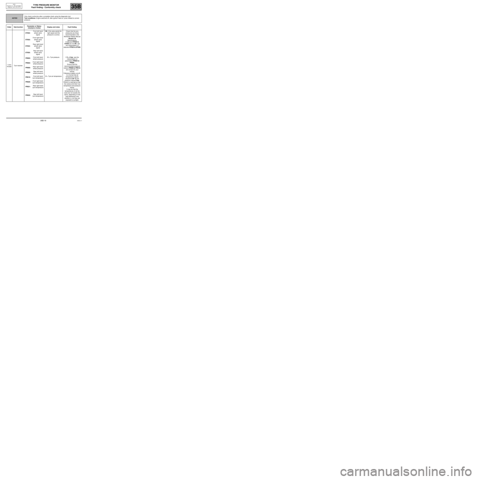
1 (con-
tinued)Tyre receiverET032:Front left-hand
wheel valve
signalOK, if the valve sends the
right signal and the
pressure is correct.Check that the tyre
pressures are those
recommended in the
Workshop Repair Manual
Section 35
Specifications.
If statuses ET032 to
ET035 are not OK, see
the interpretation of
statuses ET032 to ET035. ET033:Front right-hand
wheel valve
signal
ET034:Rear right-hand
wheel valve
signal
ET035:Rear left-hand
wheel valve
signal
PR003:Front left-hand
wheel pressureX = Tyre pressure. If X = 0 bar, see the
interpretation of
parameters PR003 to
PR006.
Ensure that the
recommended pressure
values (PR009 to PR012)
are correct for your
vehicle.
Following a battery cut-off,
it is normal that all
temperature values
should be 50 °° ° °
C and
pressure values 0 bar.
Perform a road test so that
the valves emit their true
temperature and pressure
values.
It may be that the
temperatures of all the
tyres are not exactly the
same, depending on the
load distribution and
whether or not they are
exposed to sunlight. PR004:Front right-hand
wheel pressure
PR005:Rear right-hand
wheel pressure
PR006:Rear left-hand
wheel pressure
PR019:Front left-hand
tyre temperatureX = Tyre air temperature
PR020:Front right-hand
tyre temperature
PR021:Rear right-hand
tyre temperature
PR022:Rear left-hand
tyre temperature
Edition 435B-19
Page 21 of 37
TYRE PRESSURE MONITOR
Fault finding - Conformity check
35B
UCH
Program no.: 350 and higher
Vdiag No: 48-4C-4D-4F-50
NOTESOnly check conformity after a complete check using the diagnostic tool.
Test conditions: Engine switched off, after ignition feed on, tyres inflated to correct
pressure.
Order Sub-functionParameter or Status
checked or ActionDisplay and notes Fault finding
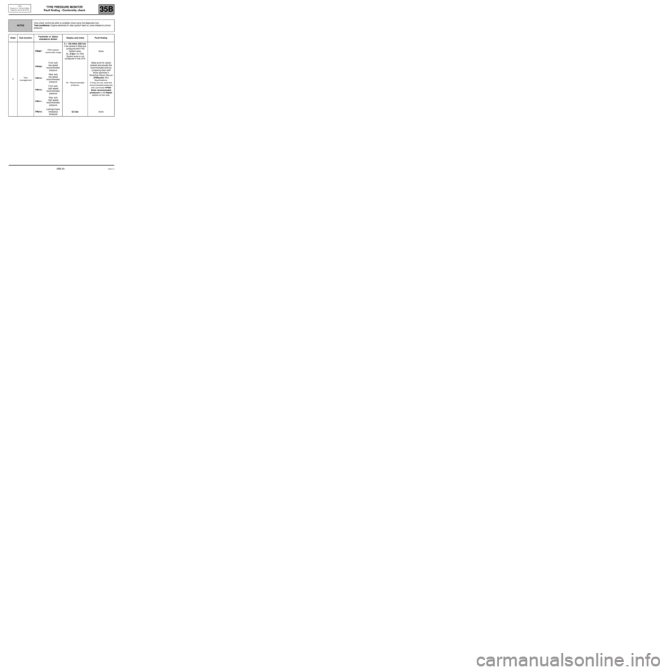
2Tyre
managementPR007:PAX system
authorised rangeX = 120 miles (200 km)
if the vehicle is fitted and
configured with PAX
System tyres.
X = 0 km if no PAX
System tyres or not
configured in the UCH.None
PR009:Front axle
low speed
recommended
pressure
X = Recommended
pressure.Make sure the values
entered are actually the
recommended ones by
comparing them with
those specified in
Workshop Repair Manual
370Section 35A
Specifications.
If they are not, write the
recommended pressures
with command VP005
Enter recommended
pressures in the Repair
section of this note. PR010:Rear axle
low speed
recommended
pressure
PR012:Front axle
high speed
recommended
pressure
PR011:Rear axle
high speed
recommended
pressure
PR014:Left/right-hand
imbalance
threshold0.5 barNone
Edition 435B-20