ignition RENAULT SCENIC 2006 J84 / 2.G Tyre Pressure Monitoring User Guide
[x] Cancel search | Manufacturer: RENAULT, Model Year: 2006, Model line: SCENIC, Model: RENAULT SCENIC 2006 J84 / 2.GPages: 37, PDF Size: 0.15 MB
Page 23 of 37
TYRE PRESSURE MONITOR
Fault finding - Conformity check
35B
UCH
Program no.: 350 and higher
Vdiag No: 48-4C-4D-4F-50
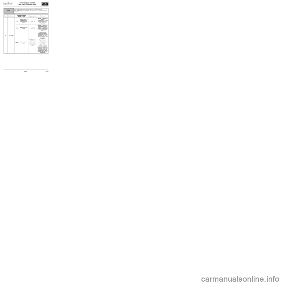
NOTESOnly check conformity after a complete check using the diagnostic tool.
Test conditions: Engine switched off, after ignition feed on, tyres inflated to correct
pressure.
Order Sub-functionParameter or Status
checked or Action Display and notes Fault finding
3Tyre displayET038:Request lighting of
Service warning
light (only for PAX
System)INACTIVEACTIVE, if a puncture is
detected.
If the pressure of all tyres
is correct, perform fault
finding on the other
computers.
ET039: STOP warning light
requestINACTIVEACTIVE, if a puncture is
detected (without PAX
System) or at the end of
the driving range following
a puncture (with PAX
System).
ET016:Buzzer activation
requestINACTIVE, if the
Tyre Pressure
Monitor system
functions normally
and tyre pressure is
correct.There is a buzzer
activation request for all
severity level 1 warnings
(puncture). The buzzer
emits a single beep when
a fault occurs.
STATUS 1:
Request for buzzer
activation when a
puncture is detected.
STATUS 2
Request for buzzer
activation to warn the
driver that the vehicle
speed is too high when the
vehicle has one or more
punctured tyres. This
information is only valid on
vehicles fitted with PAX
System tyres.
Edition 435B-22
Page 24 of 37

TYRE PRESSURE MONITOR
Fault finding - Interpretation of statuses
35B
UCH
Program no.: 350 and higher
Vdiag No: 48-4C-4D-4F-50TYRE PRESSURE MONITOR
Fault finding - Interpretation of statuses
ET032
ET033
ET034
ET035FRONT LEFT-HAND WHEEL VALVE SIGNAL
FRONT RIGHT-HAND WHEEL VALVE SIGNAL
REAR RIGHT-HAND WHEEL VALVE SIGNAL
REAR LEFT-HAND WHEEL VALVE SIGNAL
NOTESBefore carrying out any operation, apply the fault finding procedure (see Introduction).
Special notes: If a tyre pressure sensor is present in the wheel, precautions must
be taken when removing/refitting tyres. Failure to take the precautions specified
in Section 35 of the Workshop Repair Manual could result in the sensor being
damaged, and potential operating faults in the tyre pressure monitor.
OK:
Absent:
Over-inflated:
Punctured:
Under-inflated: The sensor is operating correctly and the pressure is correct.
The sensor does not transmit or is not present on the vehicle.
The sensor sends a "tyre over-inflated" signal.
The sensor sends a "tyre very under-inflated" signal (recommended pressure 0.6 bar) or a
rapid pressure loss signal.
The sensor sends a "tyre under-inflated" signal.
Make sure the signal sent by the sensor corresponds to the pressure measured with the pressure gauge.
If it does not, inflate or deflate the tyres and check that they change status.
IMPORTANT
Wait 90 seconds before checking the change of status.
Original status = over-inflated
Original status = punctured or under-
inflatedDeflate
InflateFinal status = OK or punctured or under-
inflated
Final status = OK or over-inflated
If the status still displays an incorrect signal as compared to the tyre inflation level, refer to the fault finding chart.
–If the original status is: over-inflated or under-inflated
See ALP 2 and 3 Pressure adjustment.
–If the original status is: Punctured
See ALP 7 Puncture: change the tyre.
–If the original status is: Absent
See ALP 4, 5 and 6 Sensor out of order.
–If the status does not change, replace the sensor on the wheel concerned by following the instructions and
programming procedure for the four valve codes, SC002 Program four valve codes (see Configuration and
programming).
AFTER REPAIRDeal with any other possible faults.
Switch off the ignition and carry out a road test followed by a test with the diagnostic
tool.
SSPP_V48_ET032/SSPP_V4C_ET032 /SSPP_V4D_ET032/SSPP_V4F_ET032 /SSPP_V50_ET032/
SSPP_V48_ET033/SSPP_V4C_ET033 /SSPP_V4D_ET033/SSPP_V4F_ET033 /SSPP_V50_ET033/
SSPP_V48_ET034/SSPP_V4C_ET034 /SSPP_V4D_ET034/SSPP_V4F_ET034 /SSPP_V50_ET034/
SSPP_V48_ET035/SSPP_V4C_ET035 /SSPP_V4D_ET035/SSPP_V4F_ET035 /SSPP_V50_ET035
Edition 4
35B-23
Page 25 of 37
TYRE PRESSURE MONITOR
Fault finding - Interpretation of statuses
35B
UCH
Program no.: 350 and higher
Vdiag No: 48-4C-4D-4F-50
ET036
TYRE PRESSURE IMBALANCE
NOTESBefore carrying out any operation, apply the fault finding procedure (see Introduction).
None
Note:
The threshold of imbalance between the left-hand and right-hand wheels on the same axle is 500 mbar.
Check, using a pressure gauge, that the inflation pressure of the tyres fitted on the vehicle indeed corresponds
to the pressures noted on the door, in the Driver’s Handbook or in MR 370, 35A, and if not readjust the
pressures. Ensure the correct balance of the pressures or axle(s) concerned.
If the fault is still present, contact the Techline.
AFTER REPAIRDeal with any other possible faults.
Switch off the ignition and carry out a road test followed by a test with the diagnostic
tool.
SSPP_V48_ET036/SSPP_V4C_ET036 /SSPP_V4D_ET036/SSPP_V4F_ET036 /SSPP_V50_ET036
Edition 4
35B-24
Page 26 of 37
TYRE PRESSURE MONITOR
Fault finding - Interpretation of statuses
35B
UCH
Program no.: 350 and higher
Vdiag No: 48-4C-4D-4F-50
ET037
TYRE PRESSURE APPROPRIATE FOR SPEED
NOTESBefore carrying out any operation, apply the fault finding procedure (see 35B
Introduction).
NO: If the vehicle speed is above 102 mph (170 km/h) (as an indication) for more than
3 minutes and the pressure on at least one of the tyres is 400 mbar or more below
"motorway" pressure.
YES: if the vehicle speed is below 102 mph (170 km/h) (as an indication) or if the
pressure of the four tyres corresponds to the pressure of parameters PR011 and
PR012 High speed recommended pressure, whatever the speed.
Make sure that the tyre pressures are at the recommended "motorway" pressure (see MR 370, 35A or Driver's
Handbook), and reinflate the tyres if necessary.
Check that the pressures entered (PR009 to PR012) match the manufacturer's specifications.
If the pressures entered do not correspond to the manufacturer's values, write the recommended pressures
using procedure VP005 "Write recommended pressures (see Configuration and programming.
If status ET037 remains NO, contact the Techline.
AFTER REPAIRDeal with any other possible faults.
Switch off the ignition and carry out a road test followed by a test with the diagnostic
tool.
SSPP_V48_ET037/SSPP_V4C_ET037 /SSPP_V4D_ET037/SSPP_V4F_ET037 /SSPP_V50_ET037
Edition 4
35B-25
Page 27 of 37
TYRE PRESSURE MONITOR
Fault finding - Interpretation of statuses
35B
UCH
Program no.: 350 and higher
Vdiag No: 48-4C-4D-4F-50
In the event that status ET040 is inoperative: ET040
TYRE PRESSURE MONITOR SYSTEM
NOTESBefore carrying out any operation, apply the fault finding procedure (see Introduction).
Check that no fault is present.
ACTIVE: If the four wheel valves transmit their signal and the signal is correctly received by the UCH.
INOPERATIVE: If a component is faulty or incorrectly configured.
Check in the configuration reading menu to ensure that configuration LC017 tyre pressure monitor has been
properly entered in the UCH. If this is not the case, start configuration in the "Programming" menu with
command CF023 Tyre pressure monitor, under SC008 UCH type.
Check that there is no ABS fault.
Use status ET045 RF signal received to check that the receiving aerial works correctly by trying central door
locking with the card at 4 to 5 metres to the rear right-hand of the vehicle.
If central door locking does not work, check aerial presence and positioning on the UCH.
If, after performing all these checks, no fault has been found and status ET040 is still Inoperative, contact
Techline.
AFTER REPAIRDeal with any other possible faults.
Switch off the ignition and carry out a road test followed by a test with the diagnostic
tool.
SSPP_V48_ET040/SSPP_V4C_ET040 /SSPP_V4D_ET040/SSPP_V4F_ET040 /SSPP_V50_ET040
Edition 4
35B-26
Page 31 of 37
TYRE PRESSURE MONITOR
Fault finding - Fault Finding Chart
35B
UCH
Program no.: 350 and higher
Vdiag No: 48-4C-4D-4F-50TYRE PRESSURE MONITOR
Fault finding - Fault Finding Chart
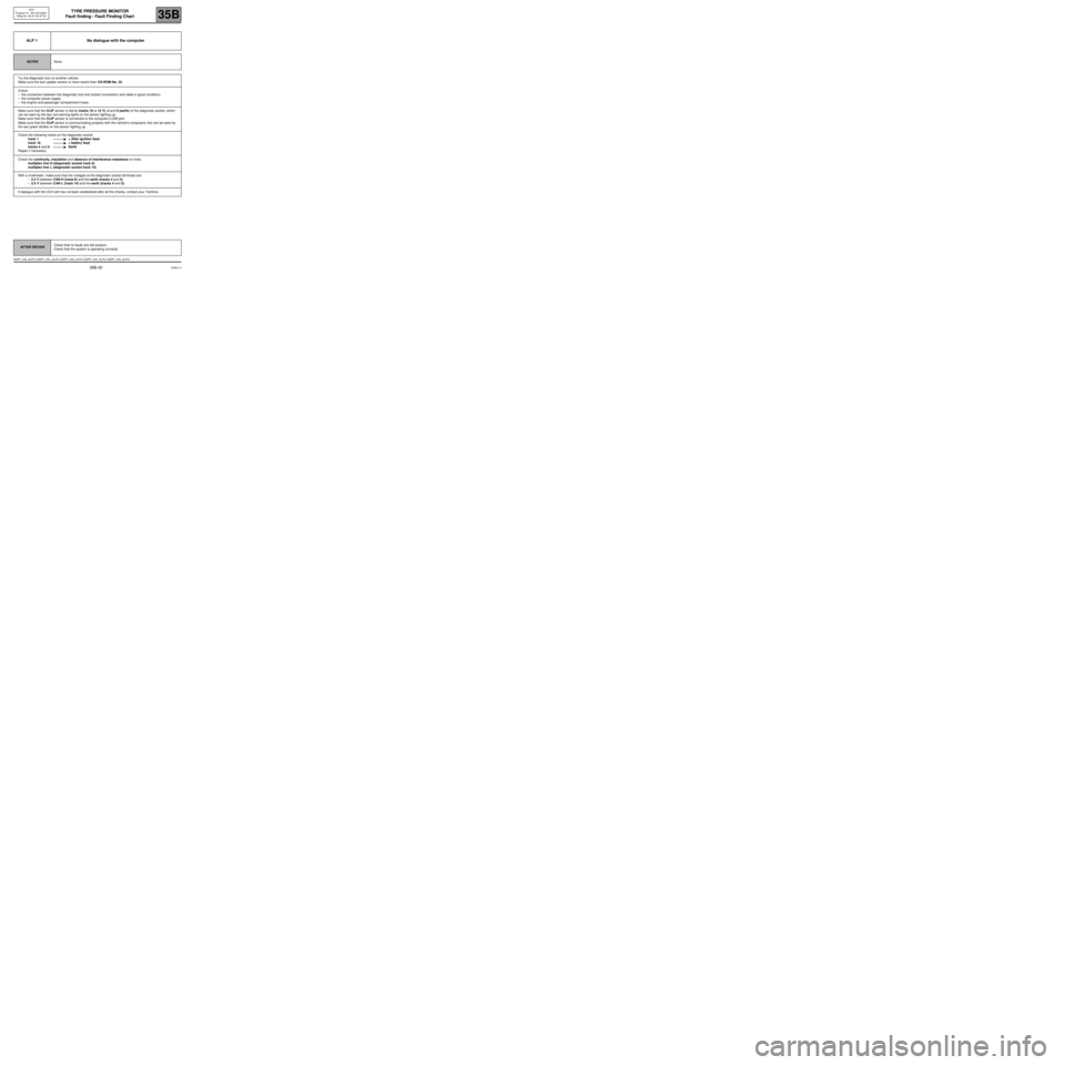
ALP 1 No dialogue with the computer
NOTESNone
Try the diagnostic tool on another vehicle.
Make sure the tool update version is more recent than CD-ROM No. 32.
Check:
–the connection between the diagnostic tool and socket (connection and cable in good condition).
–the computer power supply
–the engine and passenger compartment fuses.
Make sure that the CLIP sensor is fed by tracks 16 (+ 12 V), 4 and 5 (earth) of the diagnostic socket, which
can be seen by the two red warning lights on the sensor lighting up.
Make sure that the CLIP sensor is connected to the computer's USB port.
Make sure that the CLIP sensor is communicating properly with the vehicle's computers; this can be seen by
the two green diodes on the sensor lighting up.
Check the following tracks on the diagnostic socket:
track 1 + After ignition feed
track 16 + battery feed
tracks 4 and 5 Earth
Repair if necessary.
Check the continuity, insulation and absence of interference resistance on lines:
multiplex line H (diagnostic socket track 6)
multiplex line L (diagnostic socket track 14)
With a multimeter, make sure that the voltages at the diagnostic socket terminals are:
–2.5 V between CAN H (track 6) and the earth (tracks 4 and 5)
–2.5 V between CAN L (track 14) and the earth (tracks 4 and 5)
If dialogue with the UCH still has not been established after all the checks, contact your Techline.
AFTER REPAIRCheck that no faults are still present.
Check that the system is operating correctly.
SSPP_V48_ALP01 /SSPP_V4C_ALP01/SSPP_V4D_ALP01/SSPP_V4F_ALP01/SSPP_V50_ALP01
Edition 4
35B-30