wheel RENAULT SCENIC 2008 J84 / 2.G Passenger Comparment Connection Unit Workshop Manual
[x] Cancel search | Manufacturer: RENAULT, Model Year: 2008, Model line: SCENIC, Model: RENAULT SCENIC 2008 J84 / 2.GPages: 391
Page 25 of 391
PASSENGER COMPARTMENT CONNECTION UNIT
Fault finding - System operation
87B
87B-25
PASSENGER COMPARTMENT CONNECTION UNIT
Fault finding - System operation
87B
87B-25V9 MR-372-J84-87B000$086.mif
UCH
Vdiag No.: 44, 48,
4C, 4D, 4F, 50
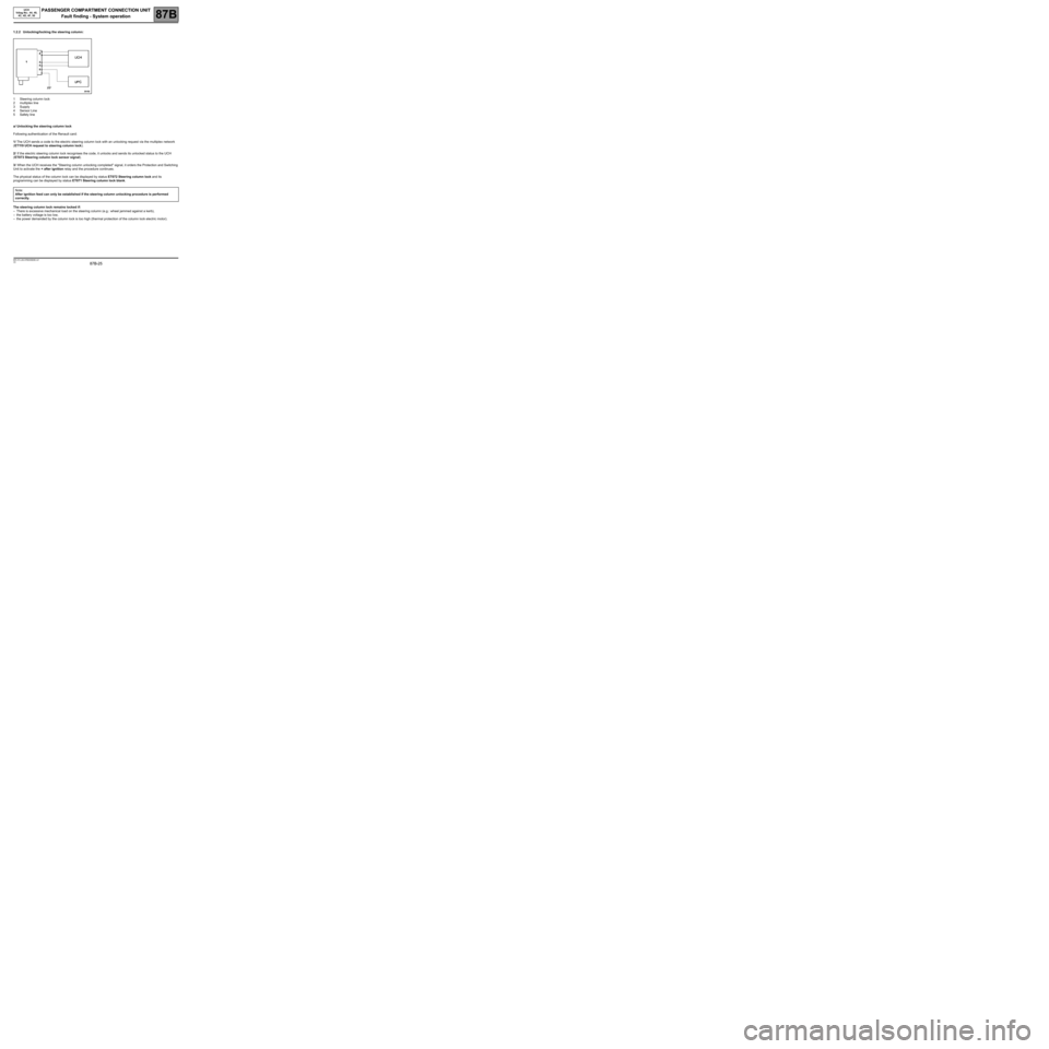
1.2.2 Unlocking/locking the steering column:
1Steering column lock
2multiplex line
3Supply
4Sensor Line
5Safety line
a/ Unlocking the steering column lock
Following authentication of the Renault card:
1/ The UCH sends a code to the electric steering column lock with an unlocking request via the multiplex network
(ET119 UCH request to steering column lock).
2/ If the electric steering column lock recognises the code, it unlocks and sends its unlocked status to the UCH
(ET073 Steering column lock sensor signal).
3/ When the UCH receives the "Steering column unlocking completed" signal, it orders the Protection and Switching
Unit to activate the + after ignition relay and the procedure continues.
The physical status of the column lock can be displayed by status ET072 Steering column lock and its
programming can be displayed by status ET071 Steering column lock blank.
The steering column lock remains locked if:
–There is excessive mechanical load on the steering column (e.g.: wheel jammed against a kerb),
–the battery voltage is too low,
–the power demanded by the column lock is too high (thermal protection of the column lock electric motor). Note:
After ignition feed can only be established if the steering column unlocking procedure is performed
correctly.
Page 46 of 391
PASSENGER COMPARTMENT CONNECTION UNIT
Fault finding - System operation
87B
87B-46
PASSENGER COMPARTMENT CONNECTION UNIT
Fault finding - System operation
87B
87B-46V9 MR-372-J84-87B000$129.mif
UCH
Vdiag No.: 44, 48,
4C, 4D, 4F, 50
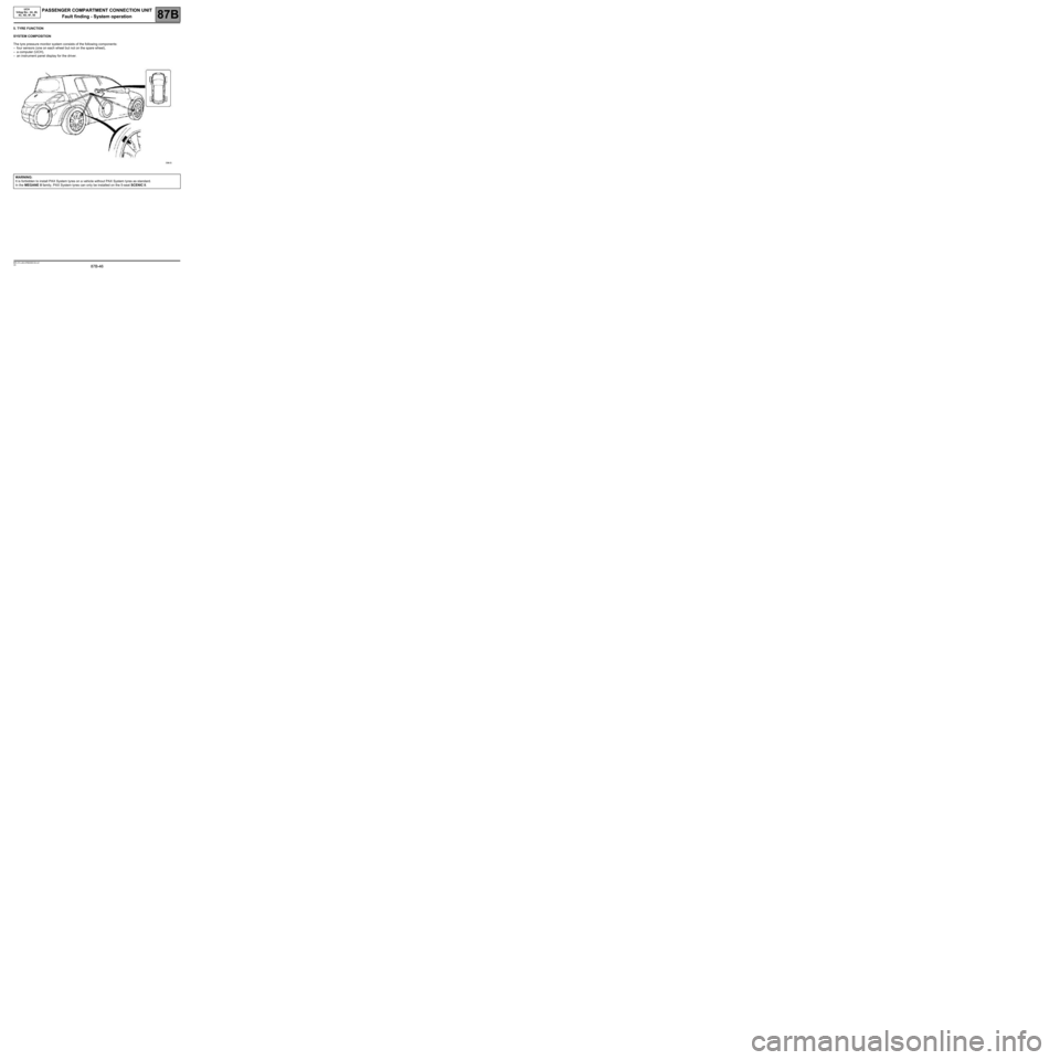
5. TYRE FUNCTION
SYSTEM COMPOSITION
The tyre pressure monitor system consists of the following components:
–four sensors (one on each wheel but not on the spare wheel),
–a computer (UCH),
–an instrument panel display for the driver.
WARNING:
It is forbidden to install PAX System tyres on a vehicle without PAX System tyres as standard.
In the MEGANE II family, PAX System tyres can only be installed on the 5-seat SCENIC II.
Page 47 of 391
PASSENGER COMPARTMENT CONNECTION UNIT
Fault finding - System operation
87B
87B-47
PASSENGER COMPARTMENT CONNECTION UNIT
Fault finding - System operation
87B
87B-47V9 MR-372-J84-87B000$129.mif
UCH
Vdiag No.: 44, 48,
4C, 4D, 4F, 50
SYSTEM OPERATION
–The valves are activated approximately 1 minute after the vehicle has been running at a speed above 12 mph
(20 km/h).
–During driving, the valves emit signals every minute.
–The valves remain active for 15 minutes after the vehicle stops, then switch to standby mode.
–In standby mode, the valves emit signals only if they detect a pressure difference between two successive
measurements exceeding 68 mbar or if the pressure difference since last emitting exceeds 68 mbar (due to tyre
cooling).
–The tyres are considered to be cold when the vehicle speed has been zero for 1h 45 min.
–The minimum time for detection of a leak is approximately 15 minutes.
–The message Inflate tyres for motorway is displayed only if the vehicle travels at more than 102 mph (170 km/
h) (as an indication) for 3 minutes and the pressure on at least one of the tyres is 400 mbar less than the
recommended pressure at low speed. This message is inactive if the tyres are inflated to motorway pressure,
irrespective of the vehicle speed.
–Alert thresholds:
–over-inflation when cold = recommended pressure + 700 mbar,
–over-inflation when hot = recommended pressure + 850 mbar,
–under-inflation = recommended pressure - 400 mbar,
–serious under-inflation = recommended pressure - 600 mbar,
–imbalance = difference in pressure between the left-hand and right-hand wheels on the same axle greater
than 500 mbar.
–Information messages for the driver:
–Stop! Tyre puncture + STOP warning light + wheel concerned is highlighted on instrument panel display +
buzzer.
–Adjust tyre pressure + the wheel concerned is highlighted on instrument panel display.
–Inflate tyres for motorway + four wheels highlighted on instrument panel display.
–Tyre sensor fault + the wheel concerned is erased.
–Electronic fault + "Service" warning light + the four wheels concerned disappear from the instrument panel
display.
–No display of the tyre inflation pressure on the instrument panel on MEGANE II.
Page 48 of 391
PASSENGER COMPARTMENT CONNECTION UNIT
Fault finding - System operation
87B
87B-48
PASSENGER COMPARTMENT CONNECTION UNIT
Fault finding - System operation
87B
87B-48V9 MR-372-J84-87B000$129.mif
UCH
Vdiag No.: 44, 48,
4C, 4D, 4F, 50
MATCHING THE VALVE TO THE TYRE
Whenever wheels are swapped over, reprogram the new valve positions in the UCH using the diagnostic tool.
The coloured rings will then have to be placed back in the location marked on the label on the driver's door.
Ring colours:
–Front left-hand: green.
–Front right-hand: yellow.
–Rear left-hand: red.
–Rear right-hand: black.
WINTER AND SUMMER TYRES
On leaving the factory, it is the summer wheel set that is configured in the UCH, but customers can fit their vehicle
with a winter set (winter wheels = wheel rims + sensors + special tyres).
The first time a set of winter wheels is fitted, program the codes of the four valves. Thereafter, whenever the set of
tyres is changed, recognition is automatic without having to touch the UCH.
Establishing communication between the UCH and the CLIP diagnostic tool:
–Connect the wire to the diagnostic socket and switch on the ignition.
–Switch on the diagnostic tool.
–Select the vehicle type and carry out the multiplex network test.
–Select the Tyre function.
–Follow the fault finding procedure described previously.
Page 57 of 391
PASSENGER COMPARTMENT CONNECTION UNIT
Fault finding - Configurations and programming
87B
87B-57
PASSENGER COMPARTMENT CONNECTION UNIT
Fault finding - Configurations and programming
87B
87B-57V9 MR-372-J84-87B000$215.mif
UCH
Vdiag No.: 44, 48,
4C, 4D, 4F, 50
5/ TYRE PRESSURE MONITORING SYSTEM FUNCTION
5.1 PROGRAMMING PROCEDURE FOR THE 4 VALVE CODES (SC002)
SC002:
Programming the four valve codes
IMPORTANT:
Any operation involving the replacement of a wheel sensor, requires perfect knowledge of the
recommendations defined in Repair Manual 364 (for Mégane II) or 370 (for Scénic II), section 35.
●Inflate the four tyres to 3.8 bar.
●Establish communication with the UCH using the diagnostic tool.
●Select the Repair mode menu.
●Select the Programming menu.
●Select line SC002 in the Tyre function.
●The stored codes and valve sets detected are displayed.
●Select the Valve set selection menu, then Summer or Winter.
●Confirm to display the Valve programming conditions table.
●Confirm by selecting next to obtain the Find valve codes menu.
●Excite each valve by holding the valve exciter against the tyre just below the valve in question.
●Start with the front left-hand wheel.
●Wait for the new code to appear on the screen before moving on to the next valve.
●The order for programming the codes is as follows:
Front left-hand Front right-hand Rear right-hand Rear left-hand
●Click on the "Confirm" button to transmit the codes to the UCH.
●Inflate the tyres to the recommended pressures.
●Carry out a road test: speed > 12 mph (20 km/h) for 10 minutes.
●Check that no message appears on the instrument panel.
IMPORTANT:
When swapping wheels over, reprogram the UCH with the new valve positions using the diagnostic tool and
program the valve codes.
The coloured rings will then have to be placed back in the location marked on the label on the driver's door.
Page 58 of 391
PASSENGER COMPARTMENT CONNECTION UNIT
Fault finding - Configurations and programming
87B
87B-58
PASSENGER COMPARTMENT CONNECTION UNIT
Fault finding - Configurations and programming
87B
87B-58V9 MR-372-J84-87B000$215.mif
UCH
Vdiag No.: 44, 48,
4C, 4D, 4F, 50
5.2 PROCEDURE FOR ENTERING THE RECOMMENDED PRESSURES (VP005)
VP005:
ENTER RECOMMENDED PRESSURES
To enter the recommended pressures correctly, use the values recommended by the manufacturer and found in
the repair manual (MR 364 (Mégane II) or MR 370 (Scénic II), Mechanical, 35A, Tyre pressure: Identification),
or Driver's handbook for the vehicle with the tyres installed on the vehicle or indicated on the label on the
driver's door.
●Select the Repair mode menu.
●Select the Other parameters menu.
●Select line VP005.
●Enter the vehicle type: Extended MPV or other.
●Enter the recommended pressures at the keyboard.
●Confirm the pressures.
●Click on Finish to end the procedure.
●Check the recommended pressures in memory:
●Select the Statuses/Parameters menu.
●Select the Tyre management menu.
●Read the parameters PR009 Front wheels low speed recommended pressure to PR012 Front wheels high
speed recommended pressure.
In the event of any problem occurring, start the operation again from the beginning.
IMPORTANT:
If the recommended pressure format is not correct or if the pressure entered is outside the permitted tolerance
values in relation to the type of vehicle selected, the following error message will be displayed: "Procedure failed:
incorrect pressure format or value outside authorised range".
Page 65 of 391
PASSENGER COMPARTMENT CONNECTION UNIT
Fault finding - Configurations and programming
87B
87B-65
PASSENGER COMPARTMENT CONNECTION UNIT
Fault finding - Configurations and programming
87B
87B-65V9 MR-372-J84-87B000$215.mif
UCH
Vdiag No.: 44, 48,
4C, 4D, 4F, 50
9) CONFIGURATION PROCEDURE FOR THE TYRE PRESSURE MONITOR FUNCTION (CF023)
10) INSTRUMENT PANEL CONFIGURATION PROCEDURE (CF145)CF023:
TYRE PRESSURE MONITOR FUNCTION
(in programming command SC008 "UCH type")
WRITING THE CONFIGURATION WITH
OR WITHOUT TYRE PRESSURE MONITOR:
●Select the Repair mode menu.
●Select the Programming menu.
●Select line SC008 then line CF023, then With or Without.
●Confirm the selection.
●Check that sure the configuration has been properly stored by checking the Read configuration menu at line
LC017 Tyre pressure monitor function.
IMPORTANT:
CONFIGURATION INCONSISTENCY BETWEEN THE INSTRUMENT PANEL AND UCH
1st case–The instrument panel detects that the tyre pressure monitor is programmed in the UCH but
not its proper configuration. The message ELECTRONIC FAULT appears, then the
4 wheels disappear on the instrument panel display, and the Service warning light comes
on.
2nd case–The instrument panel detects that the tyre pressure monitor is programmed in its own
configuration but the UCH fails to respond to any requests from the instrument panel (not
configured in UCH). The message TYRE SENSOR FAULT will appear, the four wheels
will disappear from the instrument panel display and the Service warning light will come
on.
CF145:
TYRE PRESSURE MONITOR
●After the multiplex network test, select Instrument panel.
●Select Repair mode.
●Select Write configuration.
●Select line CF145, then With or Without.
●Confirm the selection.
●Check that the configuration has been properly stored in the Read configuration menu at line LC056 Tyre
pressure monitor.
Page 69 of 391
PASSENGER COMPARTMENT CONNECTION UNIT
Fault finding - Fault summary table
87B
87B-69
PASSENGER COMPARTMENT CONNECTION UNIT
Fault finding - Fault summary table
87B
87B-69V9 MR-372-J84-87B000$258.mif
UCH
Vdiag No.: 44, 48,
4C, 4D, 4F, 50PASSENGER COMPARTMENT CONNECTION UNIT
Fault finding - Fault summary table
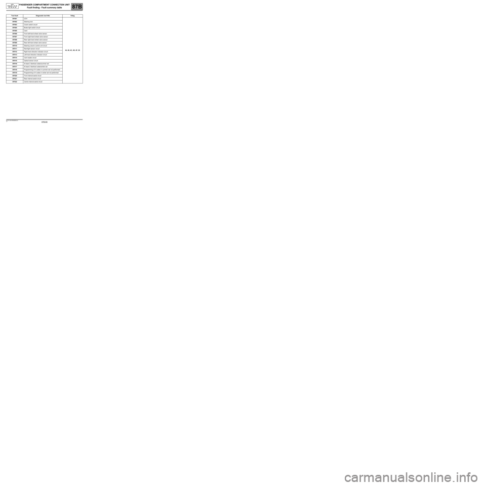
Tool fault Diagnostic tool title Vdiag
DF001UCH
44, 48, 4C, 4D, 4F, 50 DF002Steering lock
DF003Clutch switch circuit'
DF004Brake light switch circuit
DF005Card
DF006Front left-hand wheel valve sensor
DF007Front right-hand wheel valve sensor
DF008Rear right-hand wheel valve sensor
DF009Rear left-hand wheel valve sensor
DF010Steering column control unit circuit
DF011Rain/light sensor circuit
DF012Right-hand direction indicator circuit
DF013Left-hand direction indicator circuit
DF014Card reader circuit
DF015Optical sensor circuit
DF016At least 2 identical codes/summer set
DF017At least 2 identical codes/winter set
DF018Programming of 4 codes in summer set not performed
DF019Programming of 4 codes in winter set not performed
DF020Front internal aerial circuit
DF021Rear internal aerial circuit
DF022Centre internal aerial circuit
MR-372-J84-87B000$258.mif
Page 70 of 391
PASSENGER COMPARTMENT CONNECTION UNIT
Fault finding - Fault summary table
87B
87B-70
PASSENGER COMPARTMENT CONNECTION UNIT
Fault finding - Fault summary table
87B
87B-70V9 MR-372-J84-87B000$258.mif
UCH
Vdiag No.: 44, 48,
4C, 4D, 4F, 50
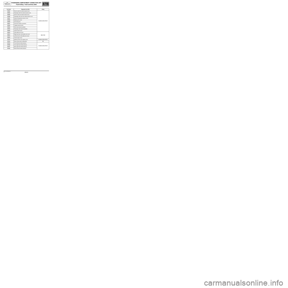
Tool fault Diagnostic tool title Vdiag
DF023Driver's side front external aerial circuit
44, 48, 4C, 4D, 4F, 50 DF024Passenger side front external aerial circuit
DF025Driver's side rear external aerial circuit
DF026Passenger side rear door external aerial circuit
DF027External temperature sensor circuit
DF029Steering lock circuit
DF030Anti-locking line
DF031One-touch window connection
DF032Tailgate external aerial
DF033Driver-side external aerial(s)
DF034Passenger-side external aerial(s)
DF035Internal aerial circuit
DF072Child safety lock circuit
4D, 4F, 50 DF073Right-hand door child safety lock circuit
DF074Left-hand door child safety lock circuit
DF075Timed supply circuit
DF147Steering column lock safety circuit44, 48, 4C, 4D, 4F, 50
DF210Rear access aerial configuration50
DF319Front left-hand wheel pressure
44, 48, 4C, 4D, 4F, 50 DF320Front right-hand wheel pressure
DF321Rear right-hand wheel pressure
DF322Rear left-hand wheel pressure
Page 73 of 391
PASSENGER COMPARTMENT CONNECTION UNIT
Fault finding - Interpretation of faults
87B
87B-73
PASSENGER COMPARTMENT CONNECTION UNIT
Fault finding - Interpretation of faults
87B
87B-73V9 MR-372-J84-87B000$301.mif
UCH
Vdiag No.: 44, 48,
4C, 4D, 4F, 50
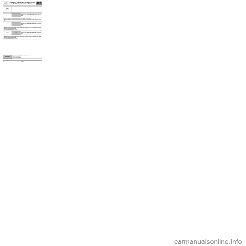
DF002
CONTINUED 1
3.DEF
NOTESAttempt to apply forced + after ignition feed to update the
faults.
Release the column by turning the steering wheel, while pressing the start button.
If the fault is still present without mechanical fault (with the wheels set straight ahead), replace the steering column
lock.
4.DEF
NOTESAttempt to apply forced + after ignition feed to update the
faults.
The steering column lock does not belong to this vehicle (or the UCH and/or the cards do not belong to this vehicle).
Ensure the conformity of the vehicle.
If the fault is still present contact Techline.
5.DEF
NOTESAttempt to apply forced + after ignition feed to update the
faults.
The steering column lock does not belong to this vehicle (or the UCH and/or the cards do not belong to this vehicle).
Ensure the conformity of the vehicle.
If the fault is still present contact Techline.
AFTER REPAIRCarry out another fault finding check on the system.
Clear the stored faults.
Deal with any other faults.