heating RENAULT SCENIC 2009 J84 / 2.G Air Conditioning Manual Conditioning Workshop Manual
[x] Cancel search | Manufacturer: RENAULT, Model Year: 2009, Model line: SCENIC, Model: RENAULT SCENIC 2009 J84 / 2.GPages: 23
Page 2 of 23
62C - 2
MANUAL AIR CONDITIONING
62C
V2 MR-372-J84-62C000$010.mif
162CMANUAL AIR CONDITIONING
Fault finding – Introduction
1. SCOPE OF THIS DOCUMENT
This document describes the fault finding procedures applicable to all manual heating and ventilation systems with
the following specifications:
2. PREREQUISITES FOR FAULT FINDING
Standard documentation:
Fault finding procedures (this manual):
–Paper (Workshop Repair Manual or Technical Note), Dialogys.
Wiring Diagrams:
–Visu-Diagram (CD-ROM), paper.
Special tooling required:
Vehicle(s): SCENIC
Function affected: heating and ventilation system
SPECIAL TOOLING REQUIRED
Multimeter and oscilloscope
Page 6 of 23
62C - 6
MANUAL AIR CONDITIONING
62C
V2 MR-372-J84-62C000$020.mif
MANUAL AIR CONDITIONING
Fault finding – System operation and track allocation
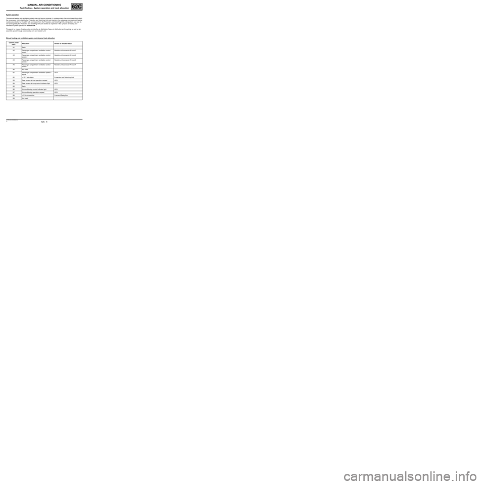
System operation
The manual heating and ventilation system does not have a computer. It consists solely of a control panel from which
the compressor (controlled by the Protection and Switching Unit and injection), the passenger compartment heating
resistors (controlled by the UCH with permission from the Protection and Switching Unit and injection) and rear de-
icer (managed by the Protection and Switching Unit) are started as explained in the synopsis of heating and
ventilation system operation in Section 62A.
The panel, by means of cables, also controls the air distribution flaps, air distribution and recycling, as well as fan
assembly speed through a connecting wire and resistor unit.
Manual heating and ventilation system control panel track allocation
Control panel
track Allocation Sensor or actuator track
A1 Earth
A2 Passenger compartment ventilation control
speed 1Resistor unit connector A track 1
A3 Passenger compartment ventilation control
speed 2Resistor unit connector A track 2
A4 Passenger compartment ventilation control
speed 3Resistor unit connector A track 3
A5 Passenger compartment ventilation control
speed 4Resistor unit connector A track 4
A6 Not used
B1 Passenger compartment ventilation speed 0
signal UCH
B2 + 12 V side lights Protection and Switching Unit
B3 Rear screen de-icer operation request UCH
B4 Rear screen de-icing control indicator light UCH
B5 Earth
B6 Air conditioning control indicator light UCH
B7 Air conditioning operation request UCH
B8 +12 V accessories Fuse and Relay box
B9 Not used
Page 7 of 23
62C - 7
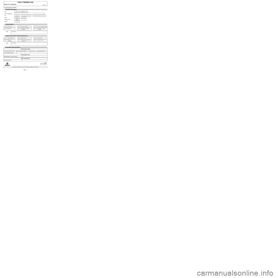
List of monitored parts: Computer
FAULT FINDING LOG
System: Air conditioningPage 1 / 2
●Administrative identification
Date: 2 0
Sheet completed by
VIN
Engine
Diagnostic tool CLIP
Version
●Customer complaint
1127 No warm air 1129 Faulty air distribution 1130 Incorrect temperature setting
1128 No cool air 1125 Heating/air conditioning:
ventilation1182 Heating/air conditioning:
demisting
OtherYour comments
●
Conditions under which the customer complaint occurs
011 When switched on 005 While driving 004 Intermittently
010 Gradual
deterioration012 When the air conditioning is
switched on009 Sudden breakdown
OtherYour comments
●
Documentation used in fault finding
Fault finding procedure
Type of fault finding manual:
Workshop Repair Manual Technical Note Assisted fault finding
Fault Finding Manual No.:
Wiring diagram used
Wiring Diagram Technical Note No.:
Other documentation
Title and/or part no.:
FD 04
Fault finding log
page to print or photocopy - page to print or photocopy - page to print or photocopy
Page 9 of 23
62C-9
MANUAL AIR CONDITIONING
Fault finding – Customer complaints62C
V2 MR-372-J84-62C000$030.mif
MANUAL AIR CONDITIONING
Fault finding – Customer complaints
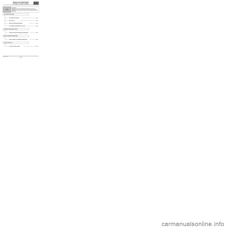
NOTESSpecial notes:
A general summary of all air-conditioning fault finding charts can be found in
Section 62A. The customer complaints listed below solely involve the heating and
ventilation system control panel. For cold air and warm air production faults, refer to
Section 62A.
AIR DISTRIBUTION PROBLEM
AIR DISTRIBUTION PROBLEM ALP 2
AIR FLOW FAULT ALP 3
INEFFICIENT WINDSCREEN DEMISTING ALP 4
NO PASSENGER COMPARTMENT VENTILATION ALP 5
PASSENGER COMPARTMENT ODOURS
UNPLEASANT ODOURS IN PASSENGER COMPARTMENT ALP 11
WATER IN PASSENGER COMPARTMENT
WATER IS PRESENT IN PASSENGER COMPARTMENT ALP 12
CONTROL PANEL FAULT
NO CONTROL PANEL LIGHTING ALP 13
Page 10 of 23
62C-10
MANUAL AIR CONDITIONING
Fault finding – Customer complaints62C
V2 MR-372-J84-62C000$030.mif
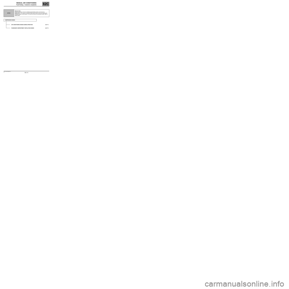
NOTESSpecial notes:
A general summary of all air-conditioning fault finding charts can be found in
Section 62A. The customer complaints listed below solely involve the heating and
ventilation system control panel. For cold air and warm air production faults, refer to
Section 62A.
COMPRESSOR NOISES
AIR CONDITIONING NOISES DURING OPERATION ALP 14
PASSENGER COMPARTMENT VENTILATION NOISES ALP 15
Page 11 of 23
62C-11
MANUAL AIR CONDITIONING
Fault finding – Fault Finding Chart62C
V2 MR-372-J84-62C000$040.mif
MANUAL AIR CONDITIONING
Fault finding – Fault Finding Chart
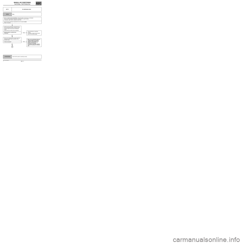
ALP 2 Air distribution fault
NOTESNone.
Make sure the air circuit (cabin filter, scuttle panel grille, air ducts etc.) is not blocked.
Ensure that the passenger compartment ventilator fan is in good condition.
If necessary, repair, clean or replace the cabin filter.
Ensure that the passenger compartment fan unit is properly sealed.
Repair if necessary.
Switch the front passenger compartment fan to
full, the temperature control to maximum heat or
maximum cold, and move the air distribution
control.
Check that the air outlet is the one selected.
Has the customer complaint been
confirmed?
NO
Remove the dashboard and visually check that
moving the control alters the position of the
distribution flaps.
Is there movement?
NO
The air distribution is operating
correctly.
If necessary, explain how the system
works to the customer again.
Make sure the distribution flaps are
in good condition, the footwell
distribution flap linkages are in
position, and that there is no
mechanical obstruction.
If necessary, recondition, clean or
replace the heating and ventilation
unit.
YES
YES
AFTER REPAIRCheck that the system is operating correctly.
Page 19 of 23
62C-19
MANUAL AIR CONDITIONING
Fault finding – Fault Finding Chart62C
V2 MR-372-J84-62C000$040.mif
AFTER REPAIRCheck that the system is operating correctly.
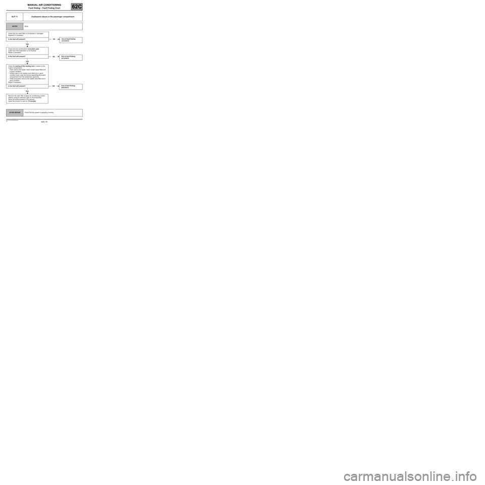
ALP 11 Unpleasant odours in the passenger compartment
NOTESNone.
Check that the cabin filter is not blocked or damaged.
Replace it if necessary.
Is the fault still present?
YES
Check that the condensation evacuation pipe
(water from the evaporator) is not blocked.
Repair if necessary.
Is the fault still present?
YES
Check the sealing of the heating unit in relation to the
engine compartment:
–Foam seal on the heater matrix coolant pipes fitted and
in good condition.
–Rubber seal on the radiator tank fitted and in good
condition (seal under the bonnet separating the engine
compartment from the windscreen aperture).
–Water evacuation valve on the radiator tank fitted and in
good condition.
Repair if necessary.
Is the fault still present?
YES
Remove the cabin filter to apply air conditioning system
cleaner using an extension pipe on the evaporator.
Spray the entire contents of the aerosol.
Leave the product to work for 15 minutes.
End of fault finding
procedure.
End of fault finding
procedure.
End of fault finding
procedure.
NO
NO
NO
Page 23 of 23
MANUAL AIR CONDITIONING
Fault finding – Fault Finding Chart62C
62C-23V2 MR-372-J84-62C000$040.mif
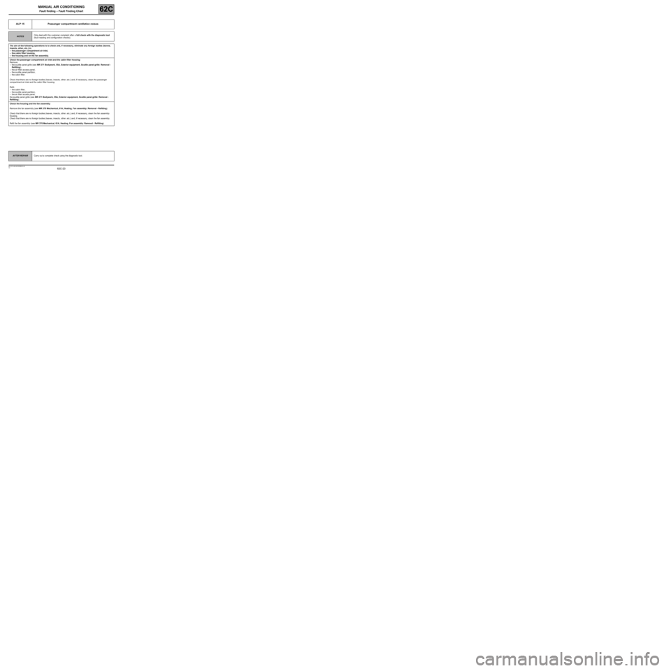
ALP 15 Passenger compartment ventilation noises
NOTESOnly deal with this customer complaint after a full check with the diagnostic tool
(fault reading and configuration checks).
The aim of the following operations is to check and, if necessary, eliminate any foreign bodies (leaves,
insects, other, etc.) in:
–the passenger compartment air inlet,
–the cabin filter housing,
–the housing and on the fan assembly.
Check the passenger compartment air inlet and the cabin filter housing:
Remove:
–the scuttle panel grille (see MR 371 Bodywork, 55A, Exterior equipment, Scuttle panel grille: Removal -
Refitting),
–the air filter access panel,
–the scuttle panel partition,
–the cabin filter.
Check that there are no foreign bodies (leaves, insects, other, etc.) and, if necessary, clean the passenger
compartment air inlet and the cabin filter housing.
Refit:
–the cabin filter,
–the scuttle panel partition,
–the air filter access panel,
the scuttle panel grille (see MR 371 Bodywork, 55A, Exterior equipment, Scuttle panel grille: Removal -
Refitting).
Check the housing and the fan assembly:
Remove the fan assembly (see MR 370 Mechanical, 61A, Heating, Fan assembly: Removal - Refitting).
Check that there are no foreign bodies (leaves, insects, other, etc.) and, if necessary, clean the fan assembly
housing.
Check that there are no foreign bodies (leaves, insects, other, etc.) and, if necessary, clean the fan assembly.
Refit the fan assembly (see MR 370 Mechanical, 61A, Heating, Fan assembly: Removal - Refitting).
AFTER REPAIRCarry out a complete check using the diagnostic tool.