RENAULT SCENIC 2009 J84 / 2.G Air Conditioning Manual Conditioning Workshop Manual
Manufacturer: RENAULT, Model Year: 2009, Model line: SCENIC, Model: RENAULT SCENIC 2009 J84 / 2.GPages: 23
Page 1 of 23
6Air conditioning
V2 MR-372-J84-62C000$TOC.mif
V2
62C
"The repair procedures given by the manufacturer in this document are based on the
technical specifications current when it was prepared.
The procedures may be modified as a result of changes introduced by the
manufacturer in the production of the various component units and accessories from
which his vehicles are constructed."
V2
All rights reserved by Renault s.a.s.
Edition Anglaise
Copying or translating, in part or in full, of this document or use of the service part
reference numbering system is forbidden without the prior written authority of
Renault s.a.s.
© Renault s.a.s. 2009
MANUAL AIR CONDITIONING
Fault finding – Introduction 62C - 2
Fault finding – System operation and track allocation 62C - 6
Fault finding – Customer complaints 62C - 9
Fault finding – Fault Finding Chart 62C - 11
Page 2 of 23
62C - 2
MANUAL AIR CONDITIONING
62C
V2 MR-372-J84-62C000$010.mif
162CMANUAL AIR CONDITIONING
Fault finding – Introduction
1. SCOPE OF THIS DOCUMENT
This document describes the fault finding procedures applicable to all manual heating and ventilation systems with
the following specifications:
2. PREREQUISITES FOR FAULT FINDING
Standard documentation:
Fault finding procedures (this manual):
–Paper (Workshop Repair Manual or Technical Note), Dialogys.
Wiring Diagrams:
–Visu-Diagram (CD-ROM), paper.
Special tooling required:
Vehicle(s): SCENIC
Function affected: heating and ventilation system
SPECIAL TOOLING REQUIRED
Multimeter and oscilloscope
Page 3 of 23
62C - 3
MANUAL AIR CONDITIONING
62C
V2 MR-372-J84-62C000$010.mif
262CMANUAL AIR CONDITIONING
Fault finding – Introduction
3. REMINDERS
Procedure
To run fault finding on the vehicle's computers, switch on the ignition in fault finding mode (+ after ignition forced
setting).
Proceed as follows:
–With the vehicle card in the card reader (scenario 1 keyless vehicle, entry level, without hands-free and
scenario 2, top of the range, hands-free),
–Press and hold start button (longer than 5 seconds) with start-up conditions not fulfilled,
–Connect the diagnostic tool and perform the required operations.
To cut off + after ignition, proceed as follows:
–Disconnect the diagnostic tool,
–Press the start button twice briefly (less then 3 seconds),
–Ensure that the + after ignition feed has been cut off by checking that the computer warning lights on the
instrument panel have gone out.
Faults
Faults are declared either present or stored (depending on whether they appeared in a certain context and have
disappeared since, or whether they remain present but have not had fault finding performed on them within the
current context).
The present or stored status of faults should be taken into consideration when the diagnostic tool is used after the
+ after ignition feed has been supplied (without acting on the system components).
For a present fault, apply the method described in the Interpretation of faults section.
For a stored fault, note the faults displayed and apply the Notes section.
If the fault is confirmed when the instructions in the Notes section are applied, the fault is present. Deal with the fault
If the fault is not confirmed, check:
–the electrical lines which correspond to the fault,
–the connectors on these lines (corrosion, bent pins, etc.),
–the resistance of the faulty component,
–the condition of the wires (melted or cut insulation, wear).
Conformity check
The conformity check is designed to check the states and parameters which do not display any faults on the
diagnostic tool when inconsistent. This phase therefore allows:
–Diagnoses of faults that do not have a fault display, and which may correspond to a customer complaint.
–Checks to ensure that the system is operating correctly and that there is no risk of a fault reappearing after
repairs.
This section gives the fault finding procedures for states and parameters and the conditions for checking them.
If a state is not behaving normally or a parameter is outside permitted tolerance values, you should refer to the
corresponding fault finding page.Note:
The left-hand and right-hand Xenon bulb computers are powered when the dipped
headlights are lit. Fault finding procedures can only be carried out on them after the
ignition has been switched on in fault finding mode (+ after ignition forced setting) and the
dipped headlights are on.
Page 4 of 23
62C - 4
MANUAL AIR CONDITIONING
Fault finding – Introduction62C
V2 MR-372-J84-62C000$010.mif
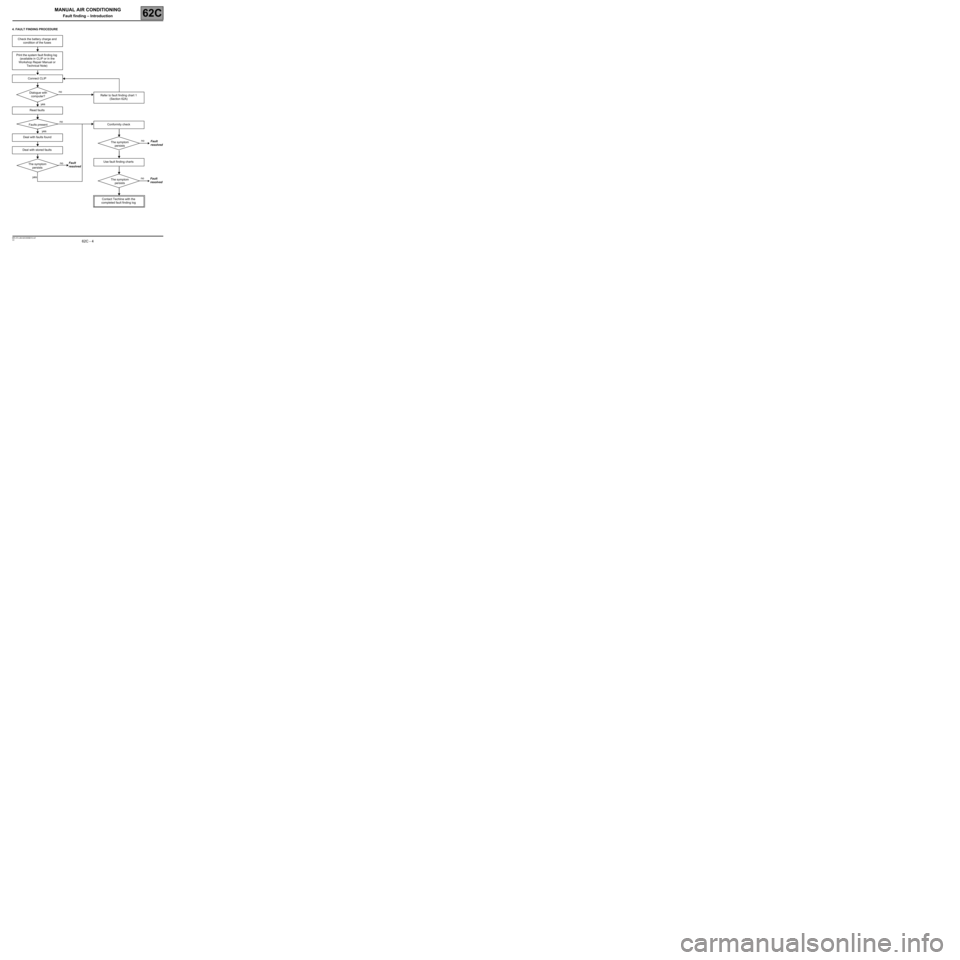
4. FAULT FINDING PROCEDURE
Check the battery charge and
condition of the fuses
Print the system fault finding log
(available in CLIP or in the
Workshop Repair Manual or
Technical Note)
Connect CLIP
Dialogue with
computer?
Read faults
Faults present
Deal with faults found
Deal with stored faults
The symptom
persists
Refer to fault finding chart 1
(Section 62A)
Conformity check
The symptom
persists
Use fault finding charts
The symptom
persists
Contact Techline with the
completed fault finding log
no
yes
no
yes
no
yesno
no
Fault
resolvedFault
resolved
Fault
resolved
Page 5 of 23
MANUAL AIR CONDITIONING
Fault finding – Introduction62C
62C - 5V2 MR-372-J84-62C000$010.mif
You will always be asked for this log:
–When requesting technical assistance from the Techline.
–For certification requests when replacing parts that must be certified.
–Which must be attached to monitored parts for which reimbursement is requested. It is therefore used to decide
whether a reimbursement will be made under warranty and leads to improved analysis of the removed parts.
6. SAFETY INSTRUCTIONS
All work on components requires the observation of safety rules to prevent physical damage or human injury:
–Make sure the battery is properly charged to avoid damaging the computers with a low charge.
–Do not smoke,
–Use the proper tools.WARNING:5. FAULT FINDING LOG
WARNING: A full fault finding procedure must be carried out for all faults on a complex system
using suitable tools. The FAULT FINDING LOG, which should be completed during the fault
finding procedure, ensures a record is kept of the procedure carried out. It is an essential item
when discussing the fault with the constructor.
IT IS THEREFORE MANDATORY TO FILL OUT A FAULT FINDING LOG EACH TIME
FAULT FINDING IS
CARRIED OUT.
Page 6 of 23
62C - 6
MANUAL AIR CONDITIONING
62C
V2 MR-372-J84-62C000$020.mif
MANUAL AIR CONDITIONING
Fault finding – System operation and track allocation
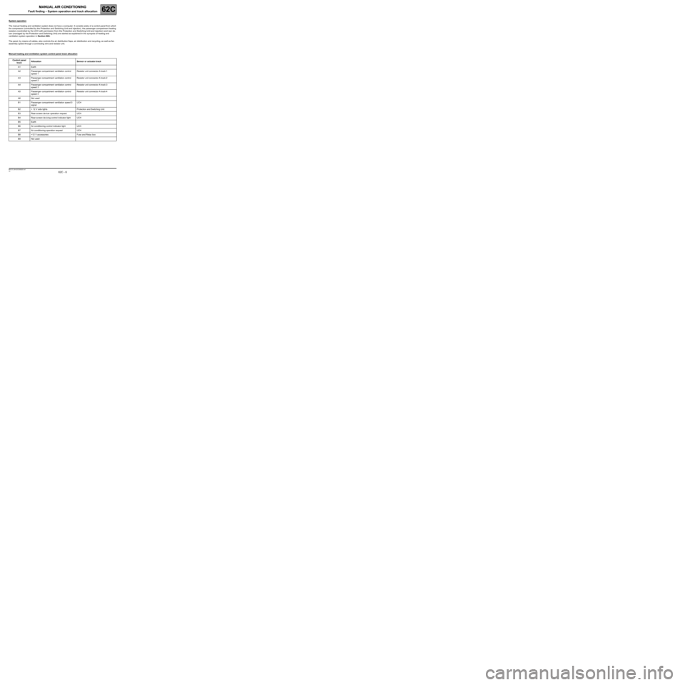
System operation
The manual heating and ventilation system does not have a computer. It consists solely of a control panel from which
the compressor (controlled by the Protection and Switching Unit and injection), the passenger compartment heating
resistors (controlled by the UCH with permission from the Protection and Switching Unit and injection) and rear de-
icer (managed by the Protection and Switching Unit) are started as explained in the synopsis of heating and
ventilation system operation in Section 62A.
The panel, by means of cables, also controls the air distribution flaps, air distribution and recycling, as well as fan
assembly speed through a connecting wire and resistor unit.
Manual heating and ventilation system control panel track allocation
Control panel
track Allocation Sensor or actuator track
A1 Earth
A2 Passenger compartment ventilation control
speed 1Resistor unit connector A track 1
A3 Passenger compartment ventilation control
speed 2Resistor unit connector A track 2
A4 Passenger compartment ventilation control
speed 3Resistor unit connector A track 3
A5 Passenger compartment ventilation control
speed 4Resistor unit connector A track 4
A6 Not used
B1 Passenger compartment ventilation speed 0
signal UCH
B2 + 12 V side lights Protection and Switching Unit
B3 Rear screen de-icer operation request UCH
B4 Rear screen de-icing control indicator light UCH
B5 Earth
B6 Air conditioning control indicator light UCH
B7 Air conditioning operation request UCH
B8 +12 V accessories Fuse and Relay box
B9 Not used
Page 7 of 23
62C - 7
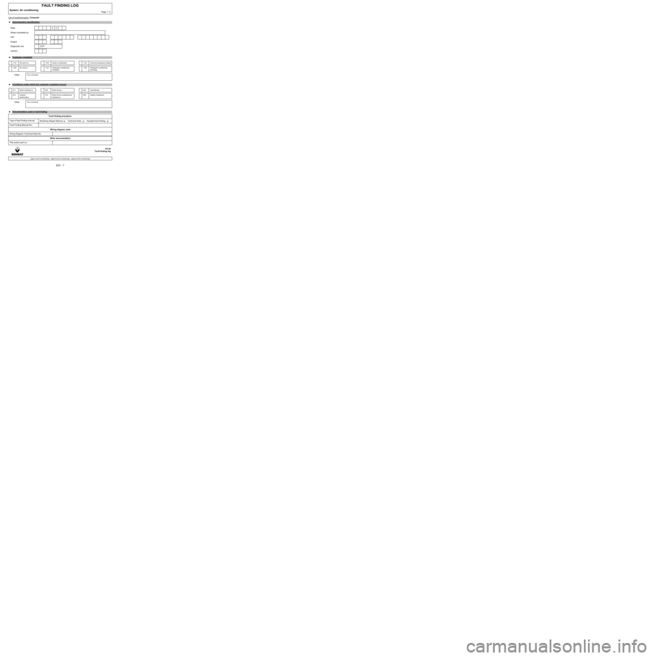
List of monitored parts: Computer
FAULT FINDING LOG
System: Air conditioningPage 1 / 2
●Administrative identification
Date: 2 0
Sheet completed by
VIN
Engine
Diagnostic tool CLIP
Version
●Customer complaint
1127 No warm air 1129 Faulty air distribution 1130 Incorrect temperature setting
1128 No cool air 1125 Heating/air conditioning:
ventilation1182 Heating/air conditioning:
demisting
OtherYour comments
●
Conditions under which the customer complaint occurs
011 When switched on 005 While driving 004 Intermittently
010 Gradual
deterioration012 When the air conditioning is
switched on009 Sudden breakdown
OtherYour comments
●
Documentation used in fault finding
Fault finding procedure
Type of fault finding manual:
Workshop Repair Manual Technical Note Assisted fault finding
Fault Finding Manual No.:
Wiring diagram used
Wiring Diagram Technical Note No.:
Other documentation
Title and/or part no.:
FD 04
Fault finding log
page to print or photocopy - page to print or photocopy - page to print or photocopy
Page 8 of 23
62C - 8
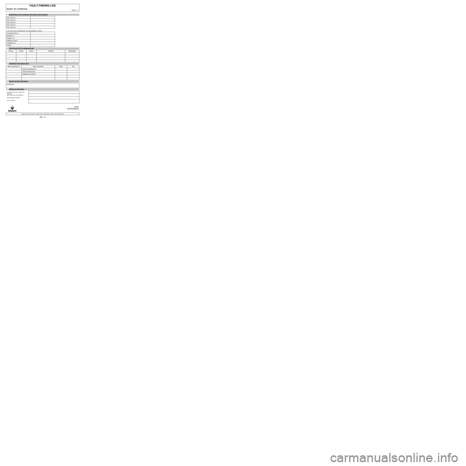
To be read with the diagnostic tool (Identification screen):
FAULT FINDING LOG
System: Air conditioningPage 2 / 2
●Identification of the computer and system parts replaced
Part 1 part no.
Part 2 part no.
Part 3 part no.
Part 4 part no.
Part 5 part no.
Computer part no.
Supplier no.
Program no.
Software version
Calibration no.
VDIAG
●Faults found with the diagnostic tool
Fault no. Present Stored Fault title Specification
●
Conditions when fault occurs
State or parameter no. Name of parameter Value Unit
External temperature
Internal temperature
Refrigerant pressure
●System-specific information
Description:
●Additional information
What factors led you to replace the
computer?
What other parts were replaced?
Other defective functions?
Your comments
FD 04
Fault finding log
page to print or photocopy - page to print or photocopy - page to print or photocopy
Page 9 of 23
62C-9
MANUAL AIR CONDITIONING
Fault finding – Customer complaints62C
V2 MR-372-J84-62C000$030.mif
MANUAL AIR CONDITIONING
Fault finding – Customer complaints
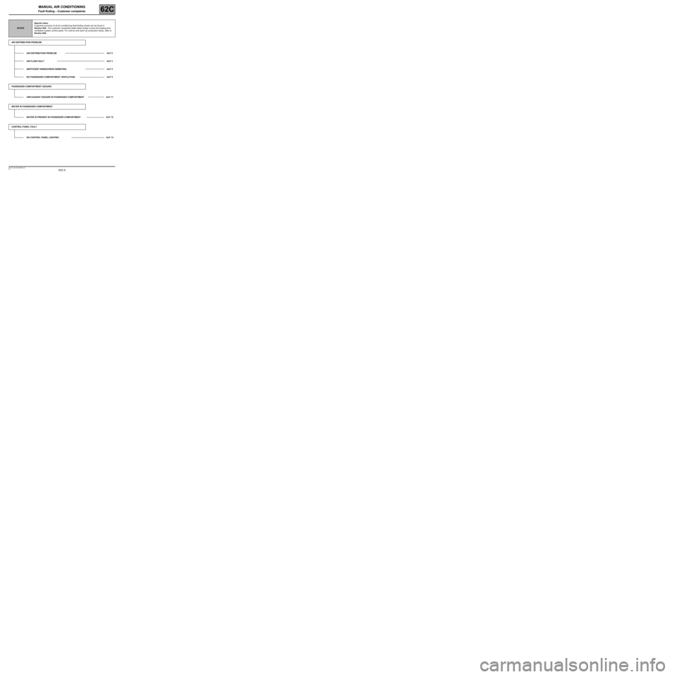
NOTESSpecial notes:
A general summary of all air-conditioning fault finding charts can be found in
Section 62A. The customer complaints listed below solely involve the heating and
ventilation system control panel. For cold air and warm air production faults, refer to
Section 62A.
AIR DISTRIBUTION PROBLEM
AIR DISTRIBUTION PROBLEM ALP 2
AIR FLOW FAULT ALP 3
INEFFICIENT WINDSCREEN DEMISTING ALP 4
NO PASSENGER COMPARTMENT VENTILATION ALP 5
PASSENGER COMPARTMENT ODOURS
UNPLEASANT ODOURS IN PASSENGER COMPARTMENT ALP 11
WATER IN PASSENGER COMPARTMENT
WATER IS PRESENT IN PASSENGER COMPARTMENT ALP 12
CONTROL PANEL FAULT
NO CONTROL PANEL LIGHTING ALP 13
Page 10 of 23
62C-10
MANUAL AIR CONDITIONING
Fault finding – Customer complaints62C
V2 MR-372-J84-62C000$030.mif
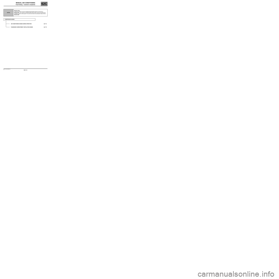
NOTESSpecial notes:
A general summary of all air-conditioning fault finding charts can be found in
Section 62A. The customer complaints listed below solely involve the heating and
ventilation system control panel. For cold air and warm air production faults, refer to
Section 62A.
COMPRESSOR NOISES
AIR CONDITIONING NOISES DURING OPERATION ALP 14
PASSENGER COMPARTMENT VENTILATION NOISES ALP 15