engine RENAULT SCENIC 2009 J84 / 2.G Automatic Transmission AJ0 BVA Owner's Manual
[x] Cancel search | Manufacturer: RENAULT, Model Year: 2009, Model line: SCENIC, Model: RENAULT SCENIC 2009 J84 / 2.GPages: 162
Page 58 of 162
AUTOMATIC TRANSMISSION
Fault finding - Interpretation of faults
23A
23A - 58V3 MR-372-J84-23A000$450.mif
AJ0 BVA
Vdiag No.: 04, 05AUTOMATIC TRANSMISSION
Fault finding - Interpretation of faults
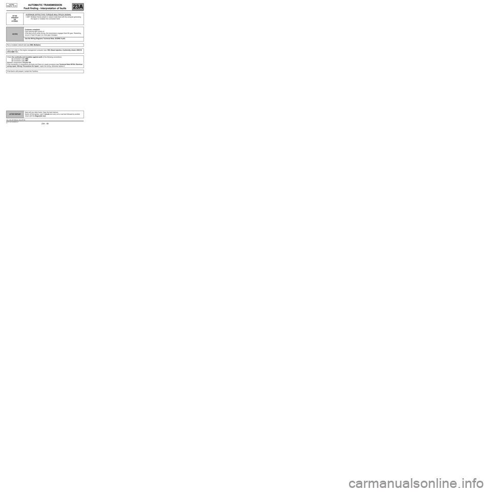
DF108
PRESENT
OR
STOREDAVERAGE EFFECTIVE TORQUE MULTIPLEX SIGNAL
1.DEF: Multiplex frames absent or values invalid (fault with the computer generating
the signal or multiplex line connection fault)
NOTESCustomer complaint:
Fault warning light comes on.
If the fault occurs while driving, the transmission engages fixed 5th gear. Restarting
occurs in fixed 3rd gear (no more gear changes).
Use the Wiring Diagrams Technical Note, SCENIC II ph2.
Run a multiplex network test (see 88B, Multiplex).
Carry out a test on the engine management computer (see 13B, Diesel injection, Conformity check) (EDC16
CP33 M9R 721).
Check the continuity and insulation against earth of the following connections:
●Connection code 3MS.
●Connection code 3MT.
Between components 119 and 120.
If the connection or connections are faulty and there is a repair procedure (see Technical Note 6015A, Electrical
wiring repair, Wiring: Precautions for repair), repair the wiring, otherwise replace it.
If the fault is still present, contact the Techline.
AFTER REPAIRDeal with any other faults. Clear the fault memory.
Switch off the ignition, wait 1 minute and carry out a road test followed by another
check with the diagnostic tool.
AJ0_V04_DF108/AJ0_V05_DF108
MR-372-J84-23A000$450.mif
Page 60 of 162
AUTOMATIC TRANSMISSION
Fault finding - Interpretation of faults
23A
23A - 60V3 MR-372-J84-23A000$450.mif
AJ0 BVA
Vdiag No.: 04, 05
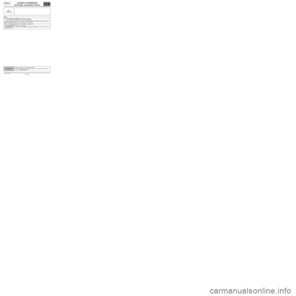
DF171
CONTINUED
Step 2:
Check the continuity and insulation of the following connection:
●Connection code AP4 between components 119 and 1337.
If the connection is faulty and there is a repair procedure (see Technical Note 6015A, Electrical wiring repair,
Wiring: Precautions for repair), repair the wiring, otherwise replace it.
Check for + after ignition feed on connection AP4 of component 1337.
If + after ignition feed is present, move on to step 1.
If + after ignition feed is not present (see 87G, engine compartment connection unit). If the fault is still present,
contact the Techline.
AFTER REPAIRDeal with any other faults. Clear the fault memory.
Switch off the ignition, wait 1 minute and carry out a road test followed by another
check with the diagnostic tool.
Page 61 of 162
AUTOMATIC TRANSMISSION
Fault finding - Interpretation of faults
23A
23A - 61V3 MR-372-J84-23A000$450.mif
AJ0 BVA
Vdiag No.: 04, 05
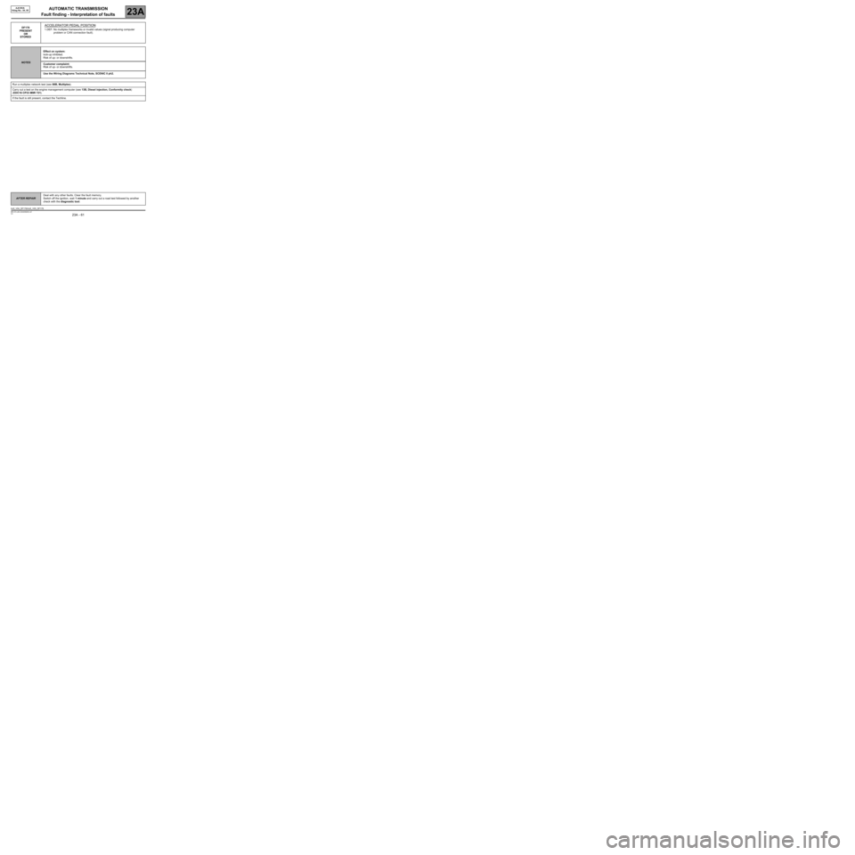
DF178
PRESENT
OR
STOREDACCELERATOR PEDAL POSITION
1.DEF: No multiplex frameworks or invalid values (signal producing computer
problem or CAN connection fault).
NOTESEffect on system:
lock-up inhibited.
Risk of up- or downshifts.
Customer complaint:
Risk of up- or downshifts.
Use the Wiring Diagrams Technical Note, SCENIC II ph2.
Run a multiplex network test (see 88B, Multiplex).
Carry out a test on the engine management computer (see 13B, Diesel injection, Conformity check)
(EDC16 CP33 M9R 721).
If the fault is still present, contact the Techline.
AFTER REPAIRDeal with any other faults. Clear the fault memory.
Switch off the ignition, wait 1 minute and carry out a road test followed by another
check with the diagnostic tool.
AJ0_V04_DF178/AJ0_V05_DF178
Page 63 of 162
AUTOMATIC TRANSMISSION
Fault finding - Interpretation of faults
23A
23A - 63V3 MR-372-J84-23A000$450.mif
AJ0 BVA
Vdiag No.: 04, 05
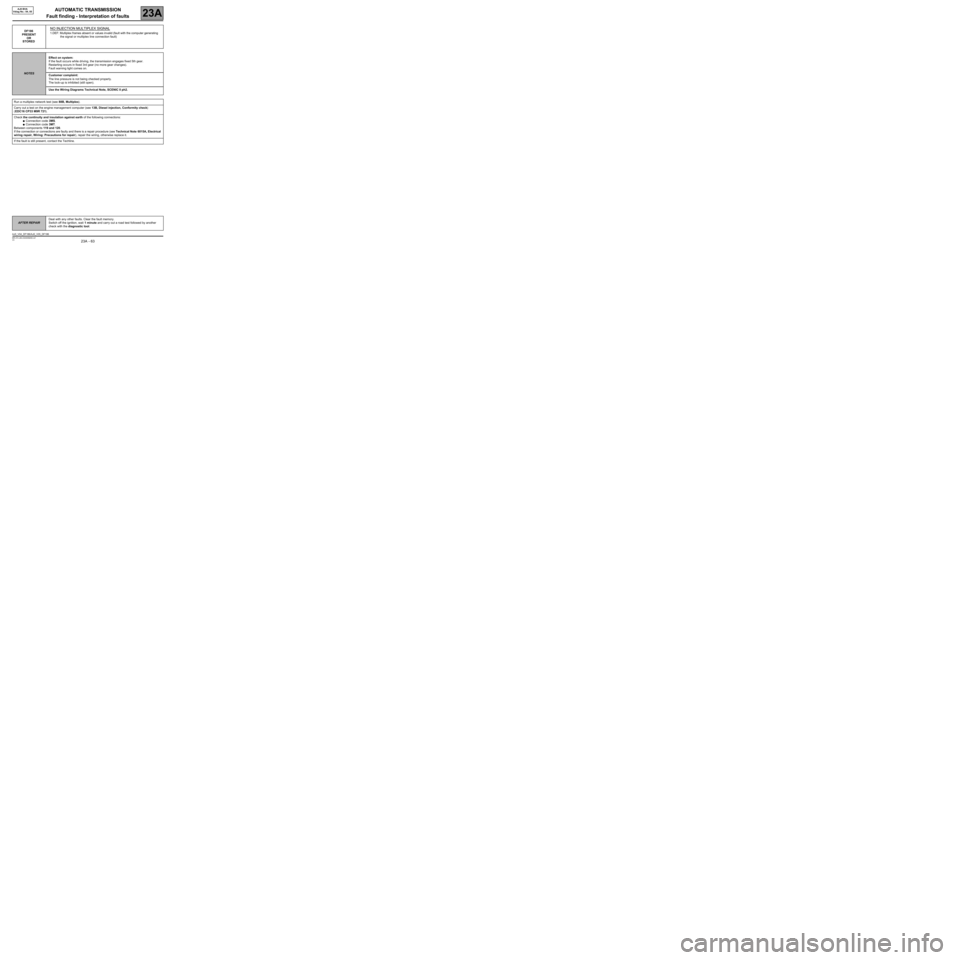
DF186
PRESENT
OR
STOREDNO INJECTION MULTIPLEX SIGNAL
1.DEF: Multiplex frames absent or values invalid (fault with the computer generating
the signal or multiplex line connection fault)
NOTESEffect on system:
If the fault occurs while driving, the transmission engages fixed 5th gear.
Restarting occurs in fixed 3rd gear (no more gear changes).
Fault warning light comes on.
Customer complaint:
The line pressure is not being checked properly.
The lock-up is inhibited (still open).
Use the Wiring Diagrams Technical Note, SCENIC II ph2.
Run a multiplex network test (see 88B, Multiplex).
Carry out a test on the engine management computer (see 13B, Diesel injection, Conformity check)
(EDC16 CP33 M9R 721).
Check the continuity and insulation against earth of the following connections:
●Connection code 3MS.
●Connection code 3MT.
Between components 119 and 120.
If the connection or connections are faulty and there is a repair procedure (see Technical Note 6015A, Electrical
wiring repair, Wiring: Precautions for repair), repair the wiring, otherwise replace it.
If the fault is still present, contact the Techline.
AFTER REPAIRDeal with any other faults. Clear the fault memory.
Switch off the ignition, wait 1 minute and carry out a road test followed by another
check with the diagnostic tool.
AJ0_V04_DF186/AJ0_V05_DF186
Page 64 of 162
AUTOMATIC TRANSMISSION
Fault finding - Interpretation of faults
23A
23A - 64V3 MR-372-J84-23A000$450.mif
AJ0 BVA
Vdiag No.: 04, 05
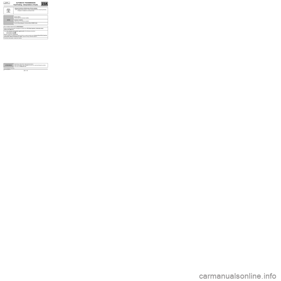
DF230
PRESENT
OR
STOREDINVALID VEHICLE SPEED MULTIPLEX SIGNAL
1.DEF: Multiplex frames absent or values invalid (fault with the computer generating
the signal or multiplex line connection fault)
NOTESSystem effects:
The anti-stall zone has been modified.
Customer complaint:
Engine stop or no customer complaint.
Use the Wiring Diagrams Technical Note, SCENIC II ph2.
Run a multiplex network test (see 88B, Multiplex).
Carry out a test on the engine management computer (see 13B, Diesel injection, Conformity check)
(EDC16 CP33 M9R 721).
Check the continuity and insulation against earth of the following connections:
●Connection code 3MS.
●Connection code 3MT.
Between components 119 and 120.
If the connection or connections are faulty and there is a repair procedure (see Technical Note 6015A, Electrical
wiring repair, Wiring: Precautions for repair), repair the wiring, otherwise replace it.
If the fault is still present, contact the Techline.
AFTER REPAIRDeal with any other faults. Clear the fault memory.
Switch off the ignition, wait 1 minute and carry out a road test followed by another
check with the diagnostic tool.
AJ0_V04_DF230/AJ0_V05_DF230
Page 65 of 162
AUTOMATIC TRANSMISSION
Fault finding - Interpretation of faults
23A
23A - 65V3 MR-372-J84-23A000$450.mif
AJ0 BVA
Vdiag No.: 04, 05
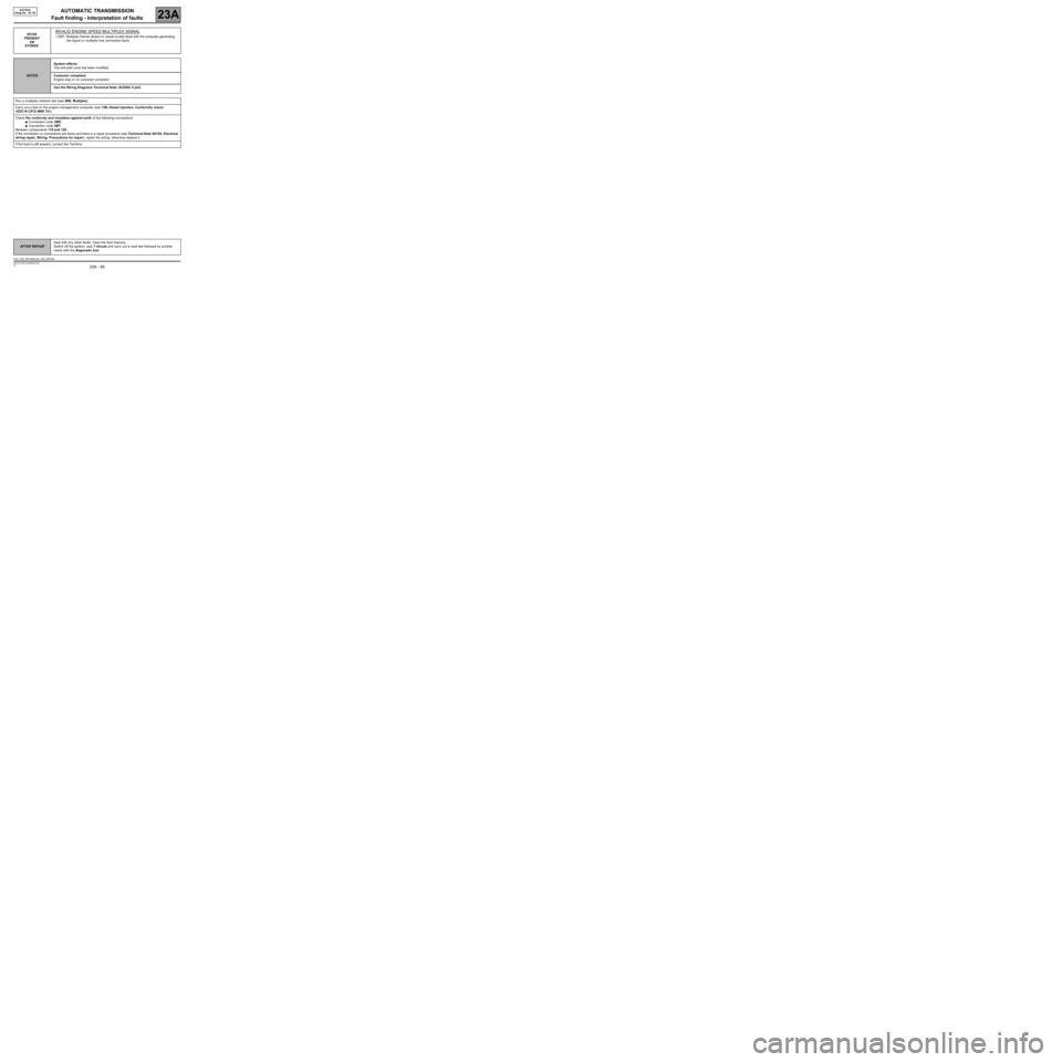
DF236
PRESENT
OR
STOREDINVALID ENGINE SPEED MULTIPLEX SIGNAL
1.DEF: Multiplex frames absent or values invalid (fault with the computer generating
the signal or multiplex line connection fault)
NOTESSystem effects:
The anti-stall zone has been modified.
Customer complaint:
Engine stop or no customer complaint.
Use the Wiring Diagrams Technical Note, SCENIC II ph2.
Run a multiplex network test (see 88B, Multiplex).
Carry out a test on the engine management computer (see 13B, Diesel injection, Conformity check)
(EDC16 CP33 M9R 721).
Check the continuity and insulation against earth of the following connections:
●Connection code 3MS.
●Connection code 3MT.
Between components 119 and 120.
If the connection or connections are faulty and there is a repair procedure (see Technical Note 6015A, Electrical
wiring repair, Wiring: Precautions for repair), repair the wiring, otherwise replace it.
If the fault is still present, contact the Techline.
AFTER REPAIRDeal with any other faults. Clear the fault memory.
Switch off the ignition, wait 1 minute and carry out a road test followed by another
check with the diagnostic tool.
AJ0_V04_DF236/AJ0_V05_DF236
Page 66 of 162
AUTOMATIC TRANSMISSION
Fault finding - Interpretation of faults
23A
23A - 66V3 MR-372-J84-23A000$450.mif
AJ0 BVA
Vdiag No.: 04, 05
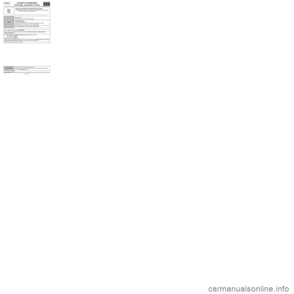
DF238
PRESENT
OR
STOREDINVALID RAW ENGINE TORQUE MULTIPLEX SIGNAL
1.DEF: Multiplex frames absent or values invalid (fault with the computer generating
the signal or multiplex line connection fault)
NOTESSystem effects:
The line pressure is not being checked properly.
Customer complaint:
Fault warning light comes on.
If the fault occurs while driving, the transmission engages fixed 5th gear.
Restarting occurs in fixed 3rd gear (no more gear changes).
Use the Wiring Diagrams Technical Note, SCENIC II ph2.
Run a multiplex network test (see 88B, Multiplex).
Carry out a test on the engine management computer (see 13B, Diesel injection, Conformity check)
(EDC16 CP33 M9R 721).
Check the continuity and insulation against earth of the following connections:
●Connection code 3MS.
●Connection code 3MT.
Between components 119 and 120.
If the connection or connections are faulty and there is a repair procedure (see Technical Note 6015A, Electrical
wiring repair, Wiring: Precautions for repair), repair the wiring, otherwise replace it.
If the fault is still present, contact the Techline.
AFTER REPAIRDeal with any other faults. Clear the fault memory.
Switch off the ignition, wait 1 minute and carry out a road test followed by another
check with the diagnostic tool.
AJ0_V04_DF238/AJ0_V05_DF238
Page 67 of 162
AUTOMATIC TRANSMISSION
Fault finding - Interpretation of faults
23A
23A - 67V3 MR-372-J84-23A000$450.mif
AJ0 BVA
Vdiag No.: 04, 05
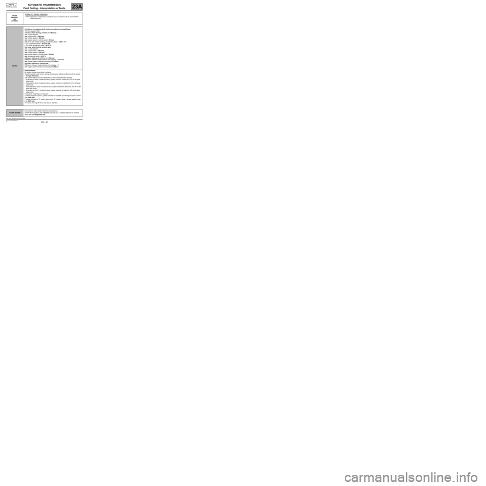
DF256
PRESENT
OR
STOREDERRATIC GEAR JUMPING
1.DEF: Hydraulic, mechanical or electrical fault on solenoid valves, deal with the
other faults first
NOTESConditions for applying fault finding procedures to stored faults:
The fault appears after:
1st case: when driving, in Drive or in Manual
ratio > ratio setpoint,
and output speed ≥ 300 rpm,
and turbine speed ≥ 300 rpm,
and engine speed ≥ turbine speed - 50 rpm,
and (if 1st with engine braking, accelerator pedal ≥ 6.25 % OR,
if 1st, accelerator pedal ≥ 30.75 % OR,
if 2nd to 6th accelerator pedal ≥ 6.25 %).
2nd case: while driving, reverse gear
ratio > ratio setpoint,
and output speed ≥ 300 rpm,
and turbine speed ≥ 300 rpm,
and engine speed ≥ turbine speed - 50 rpm,
and accelerator pedal ≥ 6.25 %.
3rd case: stationary, in Drive or in Manual
Difference between engine speed and mapping > threshold,
and engine speed increases constantly for 250 ms.
4th case: stationary, reverse gear
Difference between engine speed and mapping > 0,
and engine speed increases constantly for 250 ms.
System effects:
No engine torque transmitted to wheels.
Switch to defect mode occurs during vehicle speed safety conditions (vehicle speed
< 32 mph (54 km/h)).
The system effects will vary depending on which solenoid valve is faulty:
–If caused by brake 2 solenoid valve, system switches to fixed 2nd, 3rd or 5th gear
safe mode.
–If caused by clutch 2 solenoid valve, system switches to fixed 2nd, 3rd or 6th gear
safe mode.
–If caused by the clutch 3 solenoid valve, system switches to fixed 2nd, 3rd, 4th or 5th
gear safe mode.
–If caused by clutch 1 solenoid valve, system switches to fixed 3rd, 5th or 6th gear
safe mode.
In all cases, restarting is in 3rd gear.
If vehicle stopped in Drive, system switches to fixed 5th gear if engine speed is lower
than 2000 rpm.
If vehicle stopped in "R" mode, switching to "R" mode is done if engine speed is less
than 2000 rpm.
In reverse, moving off when "kick-down" detected.
AFTER REPAIRDeal with any other faults. Clear the fault memory.
Switch off the ignition, wait 1 minute and carry out a road test followed by another
check with the diagnostic tool.
AJ0_V04_DF256/AJ0_V05_DF256
Page 68 of 162
AUTOMATIC TRANSMISSION
Fault finding - Interpretation of faults
23A
23A - 68V3 MR-372-J84-23A000$450.mif
AJ0 BVA
Vdiag No.: 04, 05
DF256
CONTINUED 1
Note:
To accurately locate components (see location of components).
NOTESCustomer complaint:
Switch to safe mode:
–If caused by brake 2 solenoid valve, system switches to fixed 2nd, 3rd or 5th gear
safe mode.
–If caused by clutch 2 solenoid valve, system switches to fixed 2nd, 3rd or 6th gear
safe mode.
–If caused by the clutch 3 solenoid valve, system switches to fixed 2nd, 3rd, 4th or 5th
gear safe mode.
–If caused by clutch 1 solenoid valve, system switches to fixed 3rd, 5th or 6th gear
safe mode.
In all cases, restarting is in 3rd gear.
If vehicle stopped in Drive, system switches to fixed 5th gear if engine speed is lower
than 2000 rpm.
If vehicle stopped in R, switch to R if engine speed is lower than 2000 rpm.
Fault warning light comes on.
Note:
If at least one solenoid valve is faulty, replace the hydraulic distributor.
Look for any damage to the wiring and check the condition and connection of the connectors for components 119
and 754.
If the connection is faulty and there is a repair procedure (see Technical Note 6015A, Electrical wiring repair,
Wiring: Precautions for repair), repair the wiring, otherwise replace it.
AFTER REPAIRDeal with any other faults. Clear the fault memory.
Switch off the ignition, wait 1 minute and carry out a road test followed by another
check with the diagnostic tool.
Page 71 of 162
AUTOMATIC TRANSMISSION
Fault finding - Interpretation of faults
23A
23A - 71V3 MR-372-J84-23A000$450.mif
AJ0 BVA
Vdiag No.: 04, 05
DF273
PRESENT
OR
STOREDCLUTCH 1 SOLENOID VALVE CIRCUIT
1.DEF: Open circuit or short circuit
NOTESConditions for applying fault finding procedures to stored faults:
The fault appears after:
–in the event of short circuit+ or short circuit-:
Lever in "Drive" position, gear engaged = 1, 2, 3, 4, 5, 6 OR Gear engaged = 1 and
engine braking.
–in the event of open circuit:
Lever in "Drive" position, Gear engaged = 1, 2, 3, 4,
OR
Running command AC026 "Clutch 1 solenoid valve".
System effects:
–in the event of short circuit+:
No effect.
–in the event of open circuit or short circuit-:
If the fault occurs on gears 1 to 4, in D mode, the transmission switches to Neutral
(see DF256 Erratic gear jumps). Then system switches to fixed 5th gear mode after
the vehicle has stopped.
Customer complaint:
–in the event of short circuit+:
If the fault occurs while driving, the transmission engages fixed 5th gear.
Restarting in fixed 5th gear (no more gear changes).
Significant jolting during gear changes.
Fault warning light comes on.
–in the event of open circuit or short circuit-:
If the fault occurs while driving, the transmission engages fixed 5th gear.
Restarting in fixed 5th gear (gear change impossible)
Fault warning light comes on.
Use the Wiring Diagrams Technical Note, SCENIC II ph2.
Look for any damage to the wiring harness, and check the condition and connection of the automatic
transmission computer and hydraulic distributor connectors.
If the connection is faulty and there is a repair procedure (see Technical Note 6015A, Electrical wiring repair,
Wiring: Precautions for repair), repair the wiring, otherwise replace it.
Check for + after ignition feed on connection 5LW of component 754.
Is the + after ignition feed still present?
If YES, move on to step 1.
If NO, move on to step 8.
AFTER REPAIRDeal with any other faults. Clear the fault memory.
Switch off the ignition, wait 1 minute and carry out a road test followed by another
check with the diagnostic tool.
AJ0_V04_DF273/AJ0_V05_DF273