light RENAULT SCENIC 2009 J84 / 2.G Automatic Transmission AJ0 BVA Owner's Manual
[x] Cancel search | Manufacturer: RENAULT, Model Year: 2009, Model line: SCENIC, Model: RENAULT SCENIC 2009 J84 / 2.GPages: 162
Page 88 of 162
AUTOMATIC TRANSMISSION
Fault finding - Interpretation of faults
23A
23A - 88V3 MR-372-J84-23A000$495.mif
AJ0 BVA
Vdiag No.: 04, 05
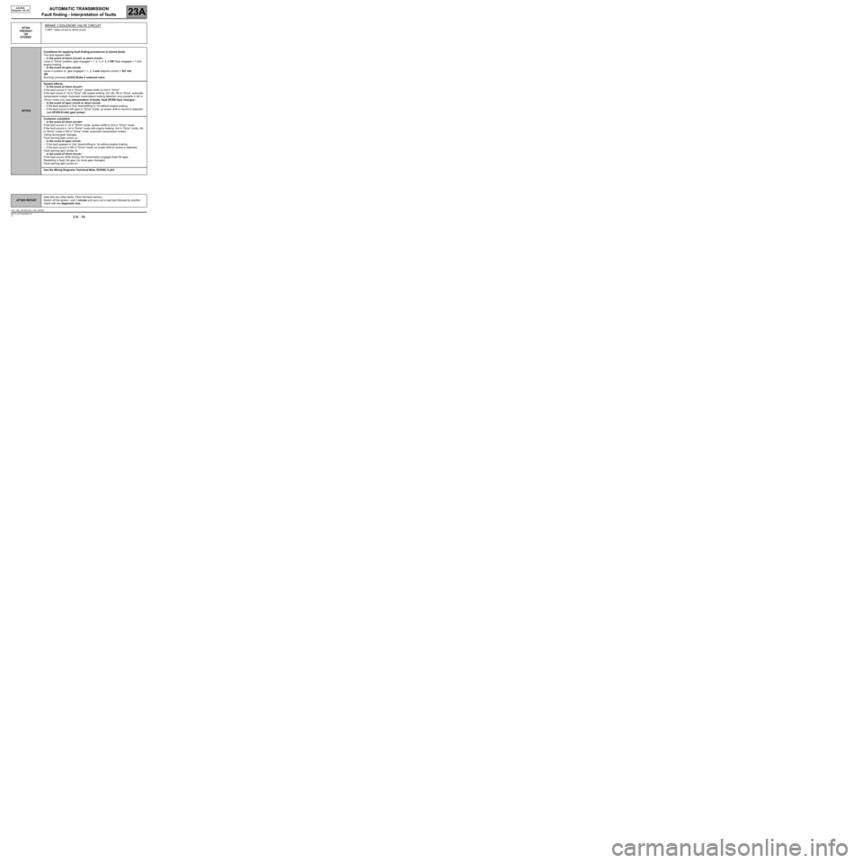
DF300
PRESENT
OR
STOREDBRAKE 2 SOLENOID VALVE CIRCUIT
1.DEF: Open circuit or short circuit
NOTESConditions for applying fault finding procedures to stored faults:
The fault appears after:
–in the event of short circuit+ or short circuit-:
Lever in "Drive" position, gear engaged = 1, 2, 3, 4, 5, 6 OR Gear engaged = 1 and
engine braking.
–in the event of open circuit:
Lever in position D, gear engaged = 1, 2, 6 and setpoint current > 937 mA
OR
Running command AC032 Brake 2 solenoid valve.
System effects:
–in the event of short circuit+:
If the fault occurs in 1st in "Drive", system shifts to 2nd in "Drive".
If the fault occurs in 1st in "Drive" with engine braking, 3rd, 4th, 5th in "Drive", automatic
transmission locked. Automatic transmission locking detection only possible in 4th in
"Drive" mode only (see Interpretation of faults, fault DF298 Gear changes).
–in the event of open circuit or short circuit-:
–If the fault appears in 2nd, downshifting to 1st without engine braking.
–If the fault occurs in 6th gear in "Drive" mode, an erratic shift to neutral is detected
(see DF256 Erratic gear jumps).
Customer complaint:
–in the event of short circuit+:
If the fault occurs in 1st in "Drive" mode, system shifts to 2nd in "Drive" mode.
If the fault occurs in 1st in "Drive" mode with engine braking, 3rd in "Drive" mode, 4th
in "Drive" mode or 5th in "Drive" mode, automatic transmission locked.
Jolting during gear changes.
Fault warning light comes on.
–in the event of open circuit:
–If the fault appears in 2nd, downshifting to 1st without engine braking.
–If the fault occurs in 6th in "Drive" mode, an erratic shift to neutral is detected.
Fault warning light comes on.
–in the event of short circuit-:
If the fault occurs while driving, the transmission engages fixed 5th gear.
Restarting in fixed 3rd gear (no more gear changes).
Fault warning light comes on.
Use the Wiring Diagrams Technical Note, SCENIC II ph2.
AFTER REPAIRDeal with any other faults. Clear the fault memory.
Switch off the ignition, wait 1 minute and carry out a road test followed by another
check with the diagnostic tool.
AJ0_V04_DF300/AJ0_V05_DF300
Page 102 of 162
AUTOMATIC TRANSMISSION
Fault finding - Interpretation of faults
23A
23A - 102V3 MR-372-J84-23A000$495.mif
AJ0 BVA
Vdiag No.: 04, 05
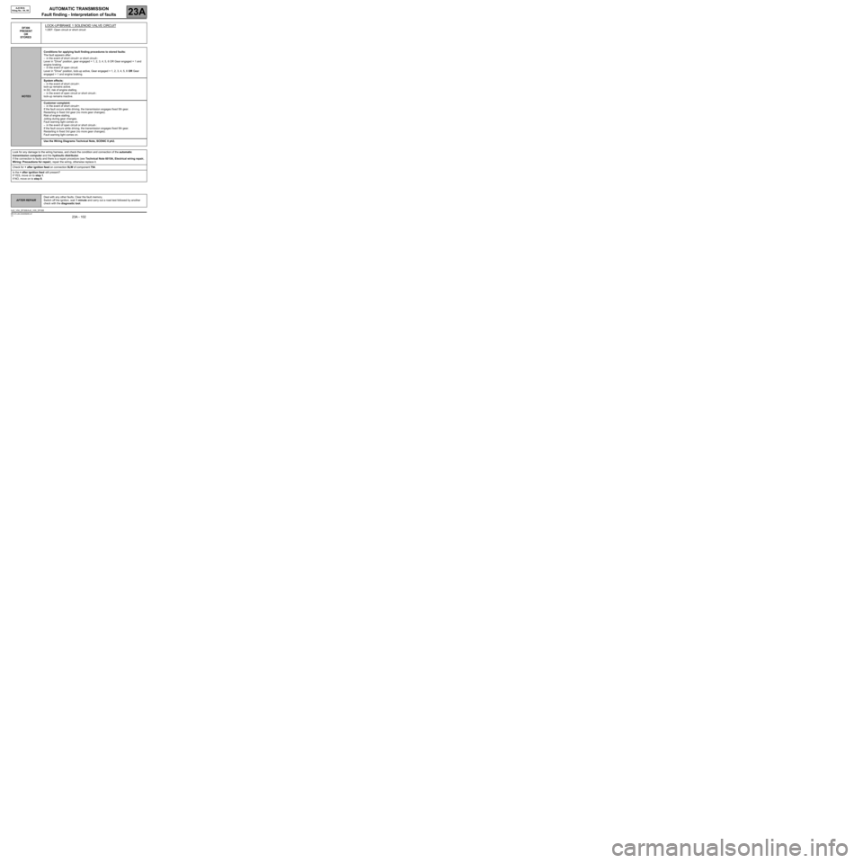
DF306
PRESENT
OR
STOREDLOCK-UP/BRAKE 1 SOLENOID VALVE CIRCUIT
1.DEF: Open circuit or short circuit
NOTESConditions for applying fault finding procedures to stored faults:
The fault appears after:
–in the event of short circuit+ or short circuit-:
Lever in "Drive" position, gear engaged = 1, 2, 3, 4, 5, 6 OR Gear engaged = 1 and
engine braking.
–in the event of open circuit:
Lever in "Drive" position, lock-up active, Gear engaged = 1, 2, 3, 4, 5, 6 OR Gear
engaged = 1 and engine braking.
System effects:
–in the event of short circuit+:
lock-up remains active.
In D2, risk of engine stalling.
–in the event of open circuit or short circuit-:
lock-up remains inactive.
Customer complaint:
–in the event of short circuit+:
If the fault occurs while driving, the transmission engages fixed 5th gear.
Restarting in fixed 3rd gear (no more gear changes).
Risk of engine stalling.
Jolting during gear changes.
Fault warning light comes on.
–in the event of open circuit or short circuit-:
If the fault occurs while driving, the transmission engages fixed 5th gear.
Restarting in fixed 3rd gear (no more gear changes).
Fault warning light comes on.
Use the Wiring Diagrams Technical Note, SCENIC II ph2.
Look for any damage to the wiring harness, and check the condition and connection of the automatic
transmission computer and the hydraulic distributor.
If the connection is faulty and there is a repair procedure (see Technical Note 6015A, Electrical wiring repair,
Wiring: Precautions for repair), repair the wiring, otherwise replace it.
Check for + after ignition feed on connection 5LW of component 754.
Is the + after ignition feed still present?
If YES, move on to step 1.
If NO, move on to step 8.
AFTER REPAIRDeal with any other faults. Clear the fault memory.
Switch off the ignition, wait 1 minute and carry out a road test followed by another
check with the diagnostic tool.
AJ0_V04_DF306/AJ0_V05_DF306
Page 106 of 162
AUTOMATIC TRANSMISSION
Fault finding - Interpretation of faults
23A
23A - 106V3 MR-372-J84-23A000$495.mif
AJ0 BVA
Vdiag No.: 04, 05
STEP 1 (checking the brake 2 solenoid valve): DF307
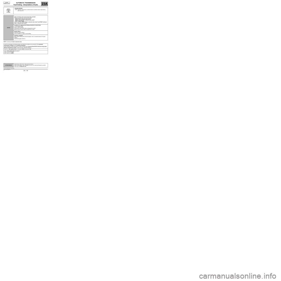
PRESENT
OR
STORED
ENGINE BRAKE
1.DEF: Hydraulic, mechanical or electrical fault on solenoid valves, deal with the
other faults first
NOTESOrder of priority in the event of more than one fault:
If there is a combination of the following faults:
–DF300 "Brake 2 solenoid valve circuit"
–DF306 "Lock-up/brake 1 solenoid valve circuit",
–DF307 "Engine brake",
deal first with faults DF300 "Brake 2 solenoid valve circuit" and DF306 "Lock-up/
brake 1 solenoid valve circuit".
Conditions for applying fault finding procedures to stored faults:
The fault appears after:
Lever in "Drive" position.
The solenoid valve control status corresponds to a fault
OR the pressure switch status corresponds to a fault.
System effects:
Significant engine braking.
lock-up inhibited (i.e. open) to avoid stalling.
Customer complaint:
Major engine braking when the fault appears, then a complete absence of engine
braking.
Fault warning light comes on.
Look for any damage to the wiring harness, and check the condition and connection of the automatic
transmission computer and the hydraulic distributor.
If the connection is faulty and there is a repair procedure (see Technical Note 6015A, Electrical wiring repair,
Wiring: Precautions for repair), repair the wiring, otherwise replace it.
Check for + after ignition feed on connection 5LW of component 754.
Is the + after ignition feed still present?
If YES, move on to step 1.
If NO, move on to step 8.
AFTER REPAIRDeal with any other faults. Clear the fault memory.
Switch off the ignition, wait 1 minute and carry out a road test followed by another
check with the diagnostic tool.
AJ0_V04_DF307/AJ0_V05_DF307
Page 113 of 162
AUTOMATIC TRANSMISSION
Fault finding - Interpretation of faults
23A
23A - 113V3 MR-372-J84-23A000$540.mif
AJ0 BVA
Vdiag No.: 04, 05AUTOMATIC TRANSMISSION
Fault finding - Interpretation of faults
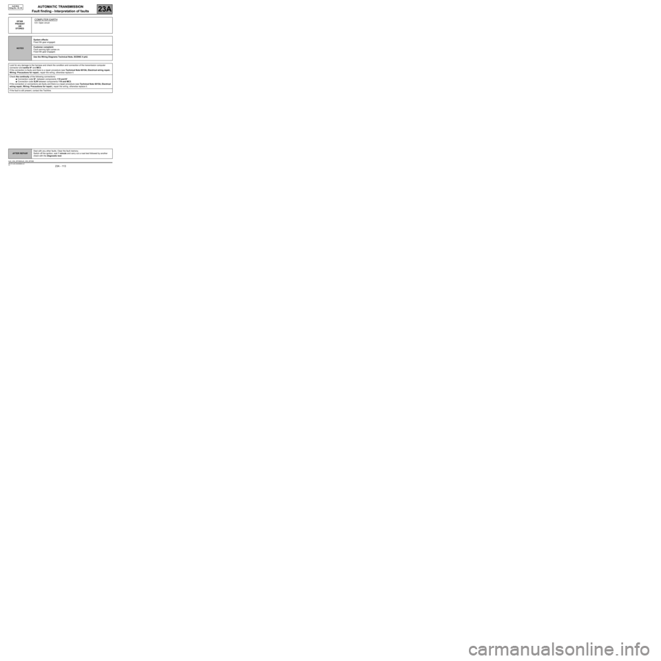
DF308
PRESENT
OR
STOREDCOMPUTER EARTH
CO: Open circuit
NOTESSystem effects:
Fixed 5th gear engaged.
Customer complaint:
Fault warning light comes on.
Fixed 5th gear engaged.
Use the Wiring Diagrams Technical Note, SCENIC II ph2.
Look for any damage to the harness and check the condition and connection of the transmission computer
connector and earths N* and MC3.
If the connection is faulty and there is a repair procedure (see Technical Note 6015A, Electrical wiring repair,
Wiring: Precautions for repair), repair the wiring, otherwise replace it.
Check the continuity of the following connections:
●Connection code N*, between components 119 and N*.
●Connection code 5LW between components 119 and MC3.
If the connection or connections are faulty and there is a repair procedure (see Technical Note 6015A, Electrical
wiring repair, Wiring: Precautions for repair), repair the wiring, otherwise replace it.
If the fault is still present, contact the Techline.
AFTER REPAIRDeal with any other faults. Clear the fault memory.
Switch off the ignition, wait 1 minute and carry out a road test followed by another
check with the diagnostic tool.
AJ0_V04_DF308/AJ0_V05_DF308
MR-372-J84-23A000$540.mif
Page 121 of 162
AUTOMATIC TRANSMISSION
Fault finding - Interpretation of statuses
23A
23A - 121V3 MR-372-J84-23A000$675.mif
AJ0 BVA
Vdiag No.: 04, 05
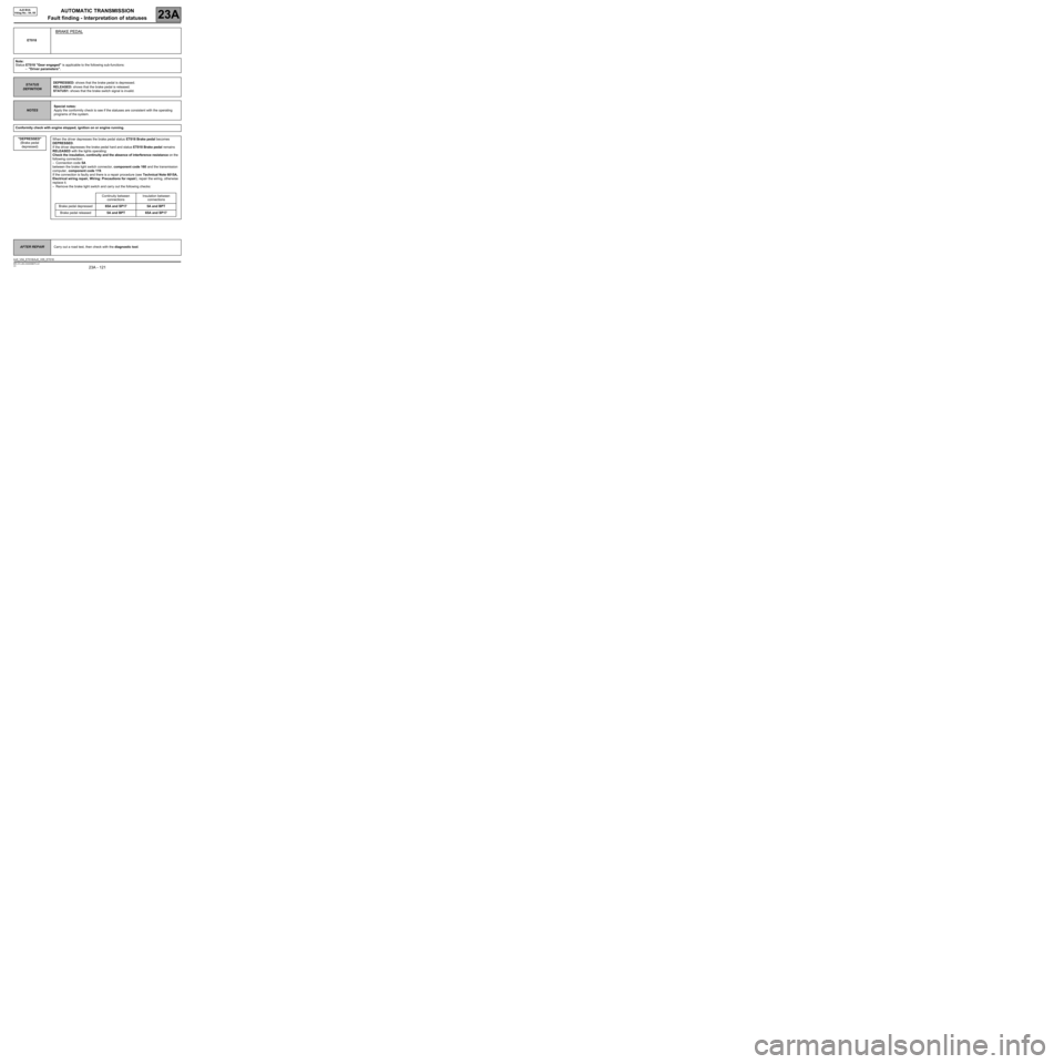
ET018
BRAKE PEDAL
Note:
Status ET018 "Gear engaged" is applicable to the following sub-functions:
–"Driver parameters".
STATUS
DEFINITIONDEPRESSED: shows that the brake pedal is depressed.
RELEASED: shows that the brake pedal is released.
STATUS1: shows that the brake switch signal is invalid.
NOTESSpecial notes:
Apply the conformity check to see if the statuses are consistent with the operating
programs of the system.
Conformity check with engine stopped, ignition on or engine running.
"DEPRESSED"
(Brake pedal
depressed)
When the driver depresses the brake pedal status ET018 Brake pedal becomes
DEPRESSED.
If the driver depresses the brake pedal hard and status ET018 Brake pedal remains
RELEASED with the lights operating:
Check the insulation, continuity and the absence of interference resistance on the
following connection:
–Connection code 5A
between the brake light switch connector, component code 160 and the transmission
computer, component code 119.
If the connection is faulty and there is a repair procedure (see Technical Note 6015A,
Electrical wiring repair, Wiring: Precautions for repair), repair the wiring, otherwise
replace it.
–Remove the brake light switch and carry out the following checks:
Continuity between
connectionsInsulation between
connections
Brake pedal depressed65A and SP17 5A and BPT
Brake pedal released5A and BPT 65A and SP17
AFTER REPAIRCarry out a road test, then check with the diagnostic tool.
AJ0_V04_ET018/AJ0_V05_ET018
Page 122 of 162
AUTOMATIC TRANSMISSION
Fault finding - Interpretation of statuses
23A
23A - 122V3 MR-372-J84-23A000$675.mif
AJ0 BVA
Vdiag No.: 04, 05
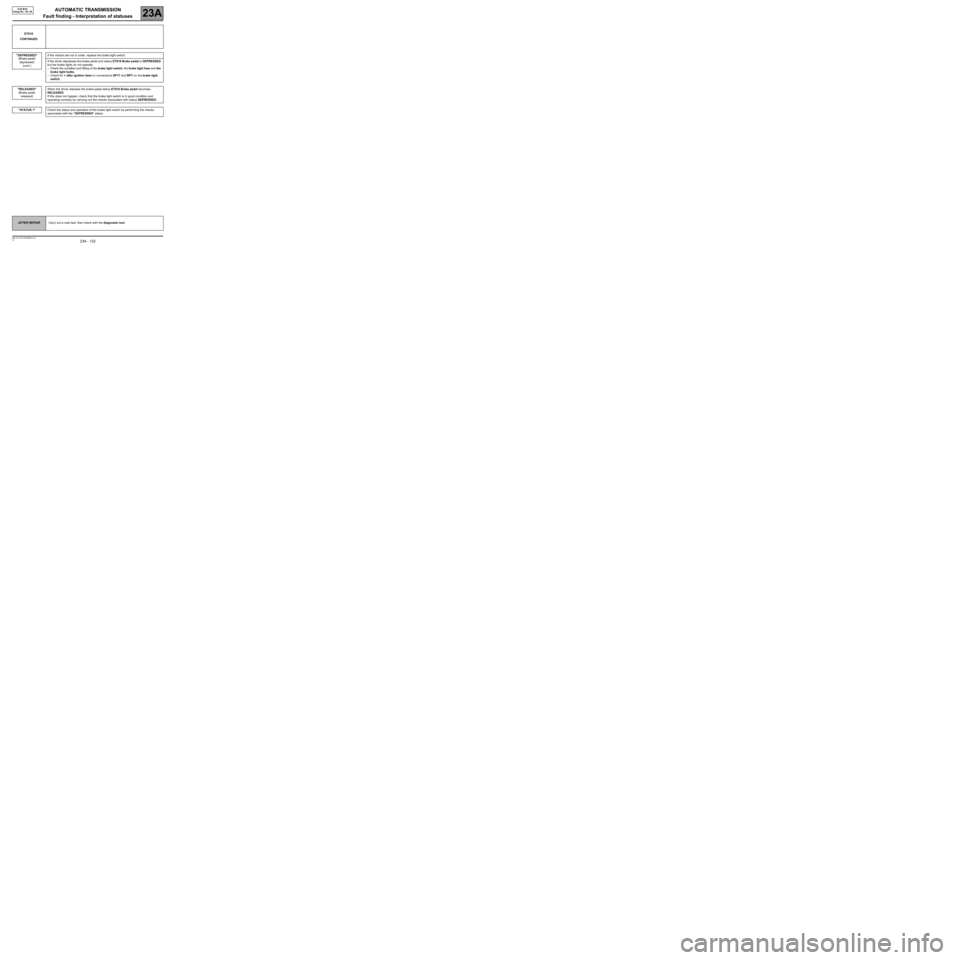
ET018
CONTINUED
"DEPRESSED"
(Brake pedal
depressed)
(cont.)
"RELEASED"
(Brake pedal
released)
"STATUS 1"
If the checks are not in order, replace the brake light switch.
If the driver depresses the brake pedal and status ET018 Brake pedal is DEPRESSED
but the brake lights do not operate:
–Check the condition and fitting of the brake light switch, the brake light fuse and the
brake light bulbs.
–Check for + after ignition feed on connections SP17 and BPT on the brake light
switch.
When the driver releases the brake pedal status ET018 Brake pedal becomes
RELEASED.
If this does not happen, check that the brake light switch is in good condition and
operating correctly by carrying out the checks associated with status DEPRESSED.
Check the status and operation of the brake light switch by performing the checks
associated with the "DEPRESSED" status.
AFTER REPAIRCarry out a road test, then check with the diagnostic tool.