sensor RENAULT SCENIC 2009 J84 / 2.G Engine And Peripherals EDC16 Owners Manual
[x] Cancel search | Manufacturer: RENAULT, Model Year: 2009, Model line: SCENIC, Model: RENAULT SCENIC 2009 J84 / 2.GPages: 273
Page 165 of 273
DIESEL INJECTION
Fault finding – Conformity check13B
13B - 165V3 MR-372-J84-13B250$540.mif
EDC16
PROGRAM NO.: C1
Vdiag No.: 51
HEATING
NOTESOnly check conformity after a complete check using the diagnostic tool. The values
shown in this conformity check are given as a guide.
Test Conditions: ENGINE AT IDLE SPEED, COOLANT TEMPERATURE > 80 ˚C.
Order FunctionParameter or Status
checked or ActionDisplay and Notes Fault finding
1Coolant
temperaturePR064:Coolant
temperatureShows the engine coolant
temperature in ˚C
Default value: 119 ˚CIn the event of a fault, refer
to the interpretation of
DF001 Coolant
temperature sensor
circuit.
2Passenger
Compartment
Heating
Resistors (RCH)ET111:Set number of
Passenger
Compartment
Heating
ResistorsDepending on the
requirements of the
injection system
(e.g. torque reduction,
power requirements), the
injection computer sets
the number of activated
passenger compartment
heating resistors
(no more or no fewer than
required)
ET111 = NOIf there is a fault,
(see 87B, Passenger
compartment
connection unit).
ET112:Passenger
Compartment
Heating
Resistor cut-offStatus ET112 shows
whether the injection
computer has requested
the passenger
compartment heating
resistors to be cut out
ET112 = NO
Page 169 of 273
DIESEL INJECTION
Fault finding – Conformity check13B
13B - 169V3 MR-372-J84-13B250$540.mif
EDC16
PROGRAM NO.: C1
Vdiag No.: 51
STARTING
NOTESOnly check conformity after a complete check using the diagnostic tool. The values
shown in this conformity check are given as a guide.
Test Conditions: ENGINE AT IDLE SPEED, COOLANT TEMPERATURE > 80 ˚C.
Order FunctionParameter or Status
checked or ActionDisplay and Notes Fault finding
1Power supplyET001:Computer + after
ignition feedPRESENTIn the event of a fault,
carry out a full fault finding
procedure on the charging
circuit.
2StartingET238:SynchronisationDONEIn the event of a fault, refer
to fault interpretation
DF195 Camshaft/engine
speed sensor
consistency.
ET076:StartingAUTHORISEDIf status ET076 is
PROHIBITED, carry out a
complete fault finding
procedure on the
multiplex network.
3Engine
operation.ET038:EngineRUNNINGNone
4Power supplyPR071:Computer feed
voltage9 V < voltage < 16 VIn the event of a fault,
consult the interpretation
of fault DF047 Computer
supply voltage.
PR358:Sensor reference
voltage3.4 V < voltage < 3.8 VNone
Page 191 of 273
DIESEL INJECTION
Fault finding – Interpretation of statuses13B
13B - 191V3 MR-372-J84-13B250$630.mif
COMPLETED
EDC16
PROGRAM NO.: C1
Vdiag No.: 51
ET238
SYNCHRONISATION
NOTESSpecial notes:
Only perform these tests if the statuses do not correspond with the system
programming functions.
WARNING
Synchronisation is carried out during the engine starting phase. This is established between the camshaft position
sensor and the TDC sensor.
Once this synchronisation has been carried out, it enables the computer to identify cylinder no. 1 and to calculate
the precise position of the cylinder's Top Dead Centre.
NOT PERFORMED
When the engine is stopped but the ignition switched on, cylinder no. 1 is no longer
indicated.
Status ET238 is NOT DONE; synchronisation between the crankshaft and the camshaft
has not been carried out.
Synchronisation is carried out during the engine starting phase.
Cylinder No. 1 is indicated and synchronisation will be performed once the engine is
started.
Status ET238 is DONE.
If after several attempts to start the engine, status ET238 remains NOT DONE, refer to
the interpretation of the following faults:
–DF005 Engine speed sensor circuit.
–DF097 Camshaft sensor circuit.
If the engine does still not start, consult the Customer complaints section, ALP2
Starting faults.
AFTER REPAIRSwitch off the ignition and carry out a road test followed by a test with the diagnostic tool
EDC16_V51_ET238
Page 206 of 273
DIESEL INJECTION
Fault finding – Parameter summary table13B
13B - 206V3 MR-372-J84-13B250$675.mif
EDC16
PROGRAM NO.: C1
Vdiag No.: 51DIESEL INJECTION
Fault finding – Parameter summary table
OCR*: opening cyclic ratioTool parameter Diagnostic tool title
PR005EGR valve opening setpoint
PR006Rail pressure regulator current
PR007Rail pressure regulator current setpoint
PR008Rail pressure setpoint
PR009Turbocharging pressure setpoint
PR011Turbocharging solenoid valve position correction
PR015Engine torque
PR016Alternator flow
PR017Fuel flow
PR022EGR valve position feedback loop difference
PR030Accelerator pedal position
PR035Atmospheric pressure
PR037Refrigerant pressure
PR038Rail pressure
PR041Turbocharging pressure
PR047Turbocharging pressure OCR*
PR048OCR* rail pressure regulation valve
PR051EGR valve position feedback
PR053Speed requested by air conditioning
PR055Engine speed
PR059Inlet air temperature
PR061Exterior air temperature
PR064Coolant temperature
PR071Computer feed voltage
PR073Air flowmeter feed voltage
PR076Refrigerant sensor voltage
PR077EGR valve position sensor voltage
MR-372-J84-13B250$675.mif
Page 207 of 273
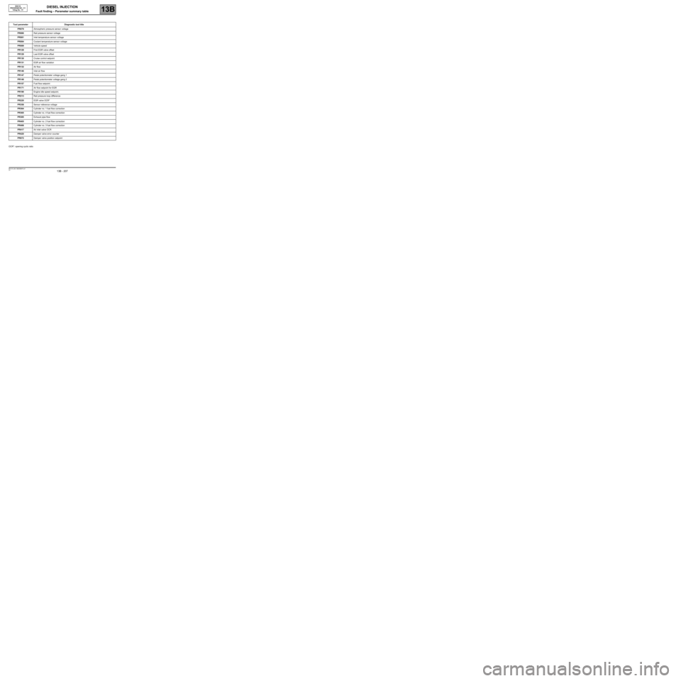
DIESEL INJECTION
Fault finding – Parameter summary table13B
13B - 207V3 MR-372-J84-13B250$675.mif
EDC16
PROGRAM NO.: C1
Vdiag No.: 51
OCR*: opening cyclic ratioTool parameter Diagnostic tool title
PR079Atmospheric pressure sensor voltage
PR080Rail pressure sensor voltage
PR081Inlet temperature sensor voltage
PR084Coolant temperature sensor voltage
PR089Vehicle speed
PR128First EGR valve offset
PR129Last EGR valve offset
PR130Cruise control setpoint
PR131EGR air flow variation
PR132Air flow
PR146Inlet air flow
PR147Pedal potentiometer voltage gang 1
PR148Pedal potentiometer voltage gang 2
PR157Fuel flow setpoint
PR171Air flow setpoint for EGR
PR190Engine idle speed setpoint.
PR213Rail pressure loop difference
PR220EGR valve OCR*
PR358Sensor reference voltage
PR364Cylinder no. 1 fuel flow correction
PR365Cylinder no. 4 fuel flow correction
PR385Exhaust pipe flow
PR405Cylinder no. 2 fuel flow correction
PR406Cylinder no. 3 fuel flow correction
PR417Air inlet valve OCR
PR420Damper valve error counter
PR672Damper valve position setpoint
Page 208 of 273
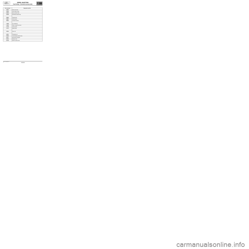
DIESEL INJECTION
Fault finding – Command summary table13B
13B -208V3 MR-372-J84-13B250$720.mif
EDC16
PROGRAM No: C1
Vdiag No.: 51DIESEL INJECTION
Fault finding – Command summary table
Tool command Diagnostic tool title
SC001Write saved data
SC002Enter injector codes
SC003Save computer data
SC036Reinitialise programming
RZ005Programming
RZ007Fault memory
RZ034Computer memory
LC009Air conditioning
LC065Water in diesel fuel sensor
LC120Cruise control
LC121Speed limiter
VP010Enter VIN
AC001Preheating unit
AC004Turbocharging solenoid valve
AC011Rail pressure regulator
AC012Damper valve
AC195Electric coolant pump
Page 216 of 273
DIESEL INJECTION
Fault finding – Interpretation of commands13B
13B -216V3 MR-372-J84-13B250$765.mif
EDC16
PROGRAM No: C1
Vdiag No.: 51
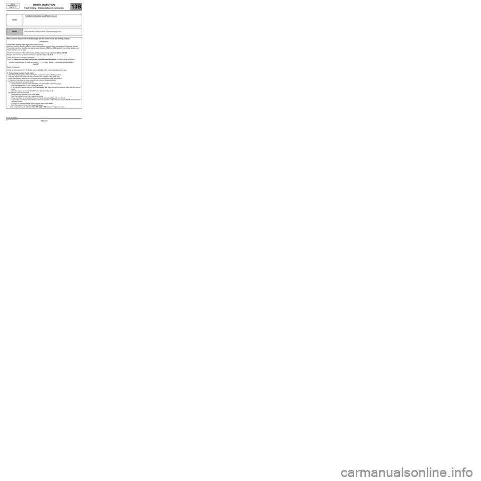
AC004
TURBOCHARGING SOLENOID VALVE
NOTESThis command is used to check the turbocharging circuit.
This command checks that the turbocharger and the control circuit are working properly.
Introduction
1-Check the sealing of the high pressure air circuit:
Pipes not joined or pierced, pressure sensor disconnected or poorly fitted (seal present), intercooler pierced.
To test the intercooler: stabilise the engine speed between 3,500 and 4,000 rpm with the vehicle stopped and
check that there are no leaks.
Check the resistance of the turbocharging limitation solenoid valve between tracks 1 and 2.
Replace the solenoid valve if its resistance is not 15.4 Ω ± 0.7 at 20˚C.
Check the injection computer connections.
Check for continuity and make sure there is no interference resistance on the following connection:
Injection computer grey 32-track connector C,
track E1Track 1 turbocharging solenoid valve
Repair if necessary.
Check for the presence of + 12 V after relay on track 2 of the turbocharging solenoid valve.
2 - Turbocharger control circuit check
–With the engine stopped, make sure that the control rod is in the resting position.
–Start the engine and make sure that the control rod actuates to the upper stop.
–(when the engine is switched off, the control rod should return to the rest position)
–If the control rod does not move correctly, carry out the following checks:
1) Vacuum pressure command check:
–Disconnect the solenoid valve inlet hose and connect it to a pressure gauge.
–Start the engine and run it at a stable idle speed.
–If the vacuum pressure does not reach 800 mbar ± 100: check the vacuum pressure circuit from the vacuum
pump.
–Stop the engine, reconnect the inlet hoses and go to step no. 2.
2) Solenoid valve control check:
–Disconnect the solenoid valve outlet hose.
–Start the engine and run it at a stable idle speed.
–Place your hand on the solenoid valve and block the outlet union with your thumb.
–If you notice no solenoid valve vibration, check the operation of the computer output (step 5). Solenoid valve
operation check:
–Connect the pressure gauge to the solenoid valve outlet union.
–Start the engine and run it at a stable idle speed.
If the vacuum pressure does not reach 800 mbar ± 100, replace the solenoid valve.
EDC16_V51_AC004
Page 219 of 273
DIESEL INJECTION
Fault finding – Interpretation of commands13B
13B -219V3 MR-372-J84-13B250$765.mif
EDC16
PROGRAM No: C1
Vdiag No.: 51
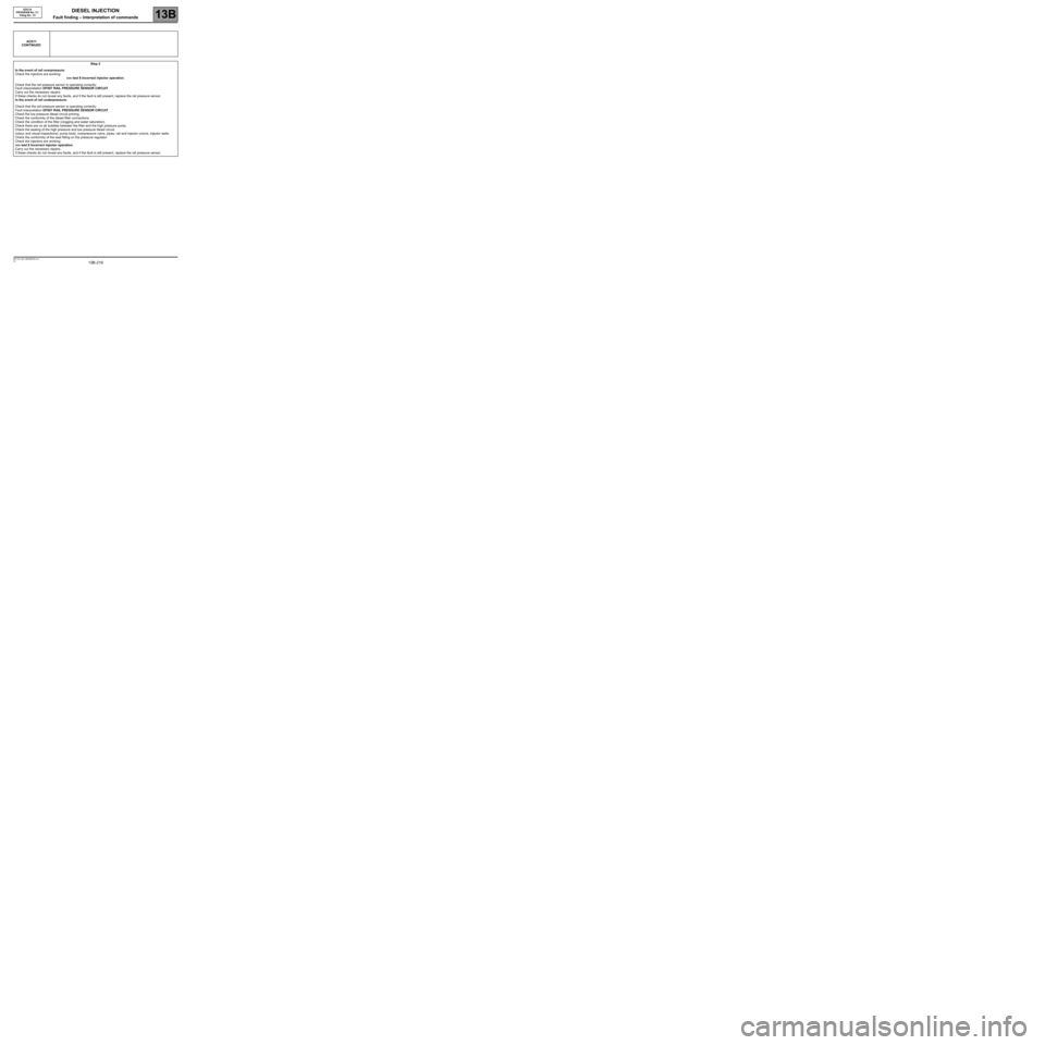
AC011
CONTINUED
Step 2
In the event of rail overpressure:
Check the injectors are working:
see test 8 Incorrect injector operation.
Check that the rail pressure sensor is operating correctly:
Fault interpretation DF007 RAIL PRESSURE SENSOR CIRCUIT.
Carry out the necessary repairs.
If these checks do not reveal any faults, and if the fault is still present, replace the rail pressure sensor.
In the event of rail underpressure:
Check that the rail pressure sensor is operating correctly:
Fault interpretation DF007 RAIL PRESSURE SENSOR CIRCUIT.
Check the low pressure diesel circuit priming.
Check the conformity of the diesel filter connections.
Check the condition of the filter (clogging and water saturation).
Check there are no air bubbles between the filter and the high pressure pump.
Check the sealing of the high pressure and low pressure diesel circuit.
(odour and visual inspections): pump body, overpressure valve, pipes, rail and injector unions, injector wells.
Check the conformity of the seal fitting on the pressure regulator.
Check the injectors are working:
see test 8 Incorrect injector operation.
Carry out the necessary repairs.
If these checks do not reveal any faults, and if the fault is still present, replace the rail pressure sensor.
Page 223 of 273
DIESEL INJECTION
Fault finding – Fault Finding Chart13B
13B -223V3 MR-372-J84-13B250$855.mif
EDC16
PROGRAM No.: C1
Vdiag No.: 51DIESEL INJECTION
Fault finding – Fault Finding Chart
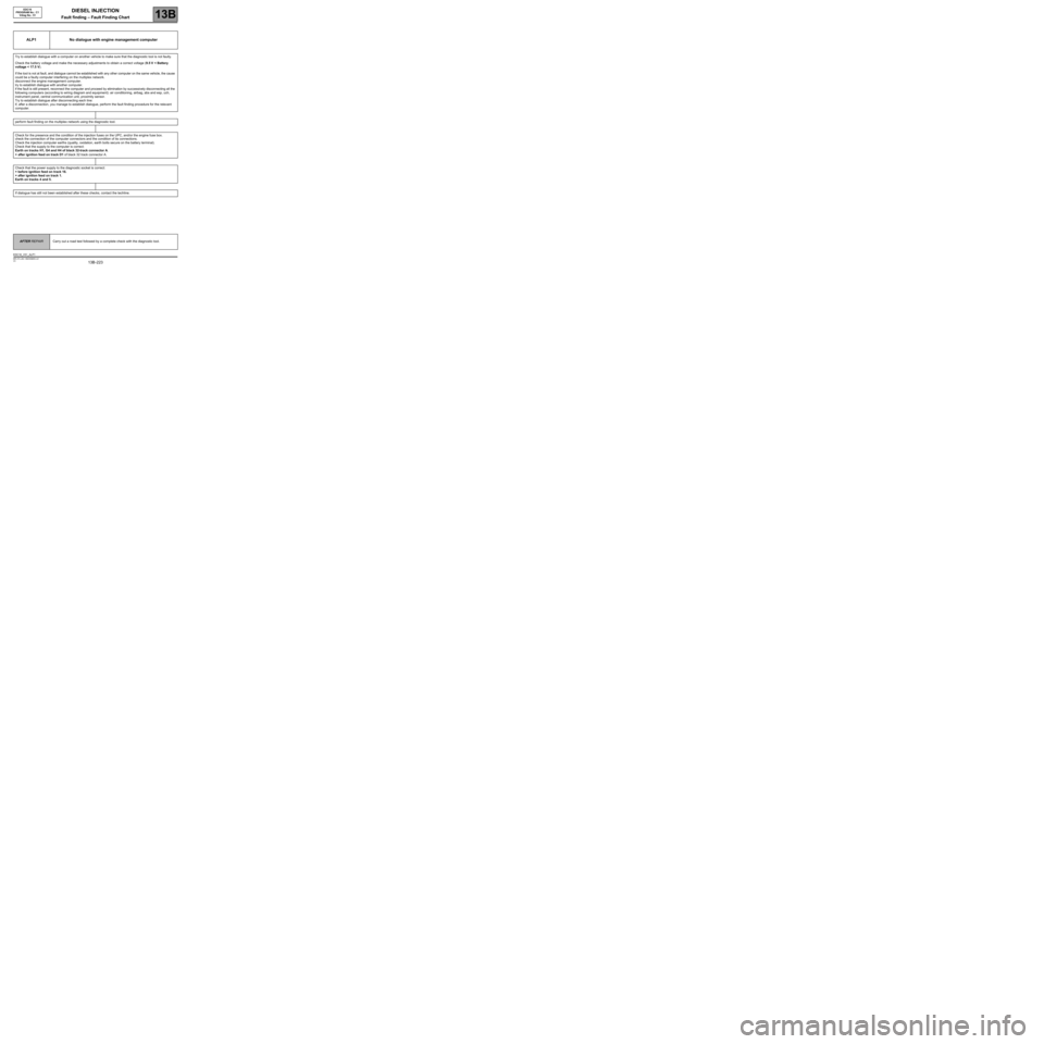
ALP1 No dialogue with engine management computer
Try to establish dialogue with a computer on another vehicle to make sure that the diagnostic tool is not faulty.
Check the battery voltage and make the necessary adjustments to obtain a correct voltage (9.5 V < Battery
voltage < 17.5 V).
If the tool is not at fault, and dialogue cannot be established with any other computer on the same vehicle, the cause
could be a faulty computer interfering on the multiplex network.
disconnect the engine management computer.
try to establish dialogue with another computer.
if the fault is still present, reconnect the computer and proceed by elimination by successively disconnecting all the
following computers (according to wiring diagram and equipment): air conditioning, airbag, abs and esp, uch,
instrument panel, central communication unit, proximity sensor.
Try to establish dialogue after disconnecting each line:
if, after a disconnection, you manage to establish dialogue, perform the fault finding procedure for the relevant
computer.
perform fault finding on the multiplex network using the diagnostic tool.
Check for the presence and the condition of the injection fuses on the UPC, and/or the engine fuse box.
check the connection of the computer connectors and the condition of its connections.
Check the injection computer earths (quality, oxidation, earth bolts secure on the battery terminal).
Check that the supply to the computer is correct:
Earth on tracks H1, G4 and H4 of black 32-track connector A.
+ after ignition feed on track D1 of black 32 track connector A.
Check that the power supply to the diagnostic socket is correct:
+ before ignition feed on track 16.
+ after ignition feed on track 1.
Earth on tracks 4 and 5.
If dialogue has still not been established after these checks, contact the techline.
AFTER REPAIRCarry out a road test followed by a complete check with the diagnostic tool.
EDC16_V51_ALP1
Page 224 of 273
DIESEL INJECTION
Fault finding – Fault Finding Chart13B
13B -224V3 MR-372-J84-13B250$855.mif
EDC16
PROGRAM No.: C1
Vdiag No.: 51
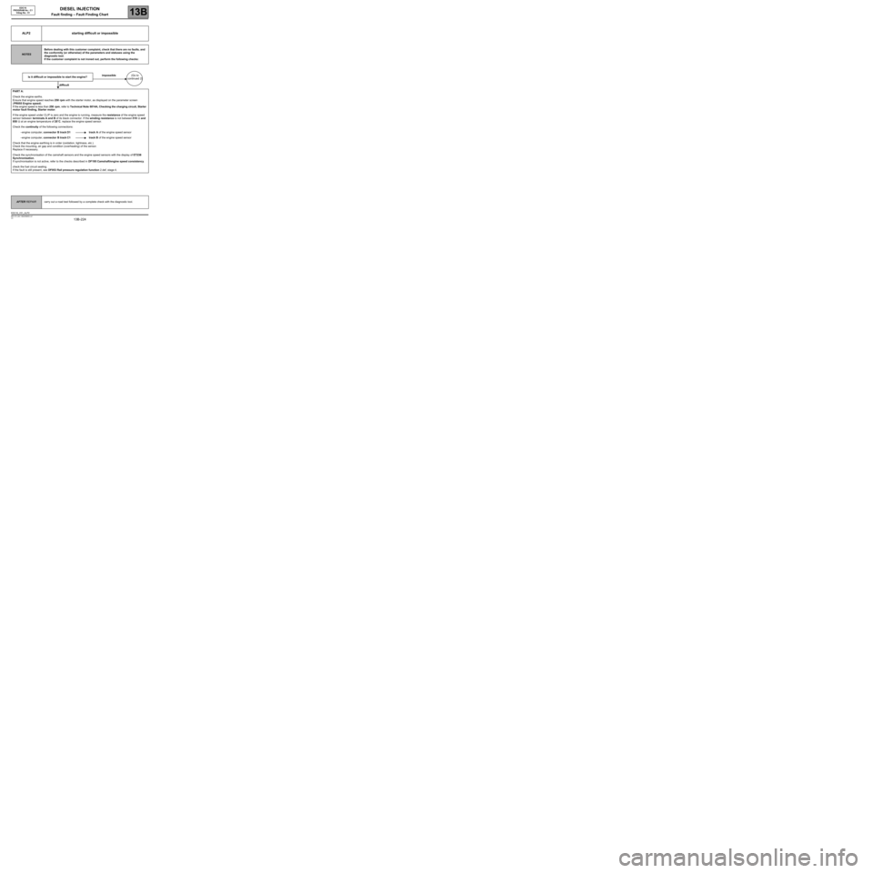
ALP2 starting difficult or impossible
NOTESBefore dealing with this customer complaint, check that there are no faults, and
the conformity (or otherwise) of the parameters and statuses using the
diagnostic tool.
If the customer complaint is not ironed out, perform the following checks:
Is it difficult or impossible to start the engine?impossible(Go to
continued 2)
difficult
PART A:
Check the engine earths.
Ensure that engine speed reaches 250 rpm with the starter motor, as displayed on the parameter screen
(PR055 Engine speed).
If the engine speed is less than 250 rpm, refer to Technical Note 6014A, Checking the charging circuit, Starter
motor fault finding, Starter motor.
If the engine speed under CLIP is zero and the engine is running, measure the resistance of the engine speed
sensor between terminals A and B of its black connector. If the winding resistance is not between 510 Ω and
850 Ω at an engine temperature of 20˚C, replace the engine speed sensor.
Check the continuity of the following connections:
–engine computer, connector B track D1 track A of the engine speed sensor
–engine computer, connector B track C1 track B of the engine speed sensor
Check that the engine earthing is in order (oxidation, tightness, etc.).
Check the mounting, air gap and condition (overheating) of the sensor.
Replace if necessary.
Check the synchronisation of the camshaft sensors and the engine speed sensors with the display of ET238
Synchronisation.
If synchronisation is not active, refer to the checks described in DF195 Camshaft/engine speed consistency.
check the fuel circuit sealing.
If the fault is still present, see DF053 Rail pressure regulation function 2.def, stage 4.
AFTER REPAIRcarry out a road test followed by a complete check with the diagnostic tool.
EDC16_V51_ALP2