ESP RENAULT SCENIC 2009 J84 / 2.G Engine And Peripherals EDC16 User Guide
[x] Cancel search | Manufacturer: RENAULT, Model Year: 2009, Model line: SCENIC, Model: RENAULT SCENIC 2009 J84 / 2.GPages: 273
Page 80 of 273
DIESEL INJECTION
Fault finding – Interpretation of faults13B
13B-80V3 MR-372-J84-13B250$360.mif
EDC16
PROGRAM No.: C1
Vdiag No.: 51
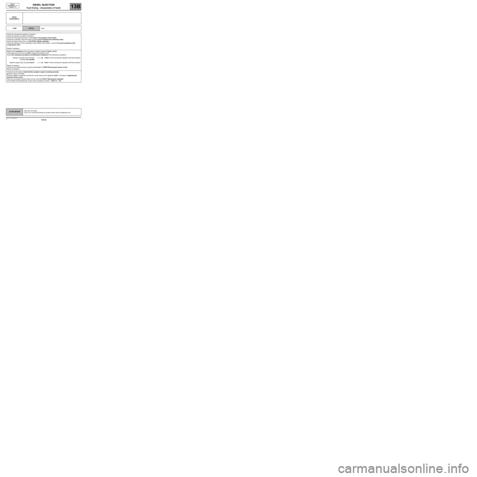
DF053
CONTINUED 2
1.DEF
NOTESNone
Ch eck the rail pressure regulator connectors.
Ch eck the in jection computer connections.
Ch eck the lo w p ressu re circu it b y runningtest 2Low pressure circuit check.
Ch eck the conformityof the fuel used by applyingtest 10 Diesel f uel conformity check.
Ch eck the in jector return flow, runtest 8 Poor injector operation.
Ch eck theoperation of the overpressure valve if fitted to the vehicle, run test11 Incorrectopera tion of the
ov erpressure valve.
Re pair if n ecessa ry.
Measure theresistanceof the rail press u r e regulator betweentracks 1 and 2.
If the resistance is not3±1Ωat20˚C,replacetheinjection pump.
Ch eckthe continuity and absence of interference resistanceof the followingconnections:
Injection computer brown 48-track
connectorB,track M4Track 2 of the rail pressure regulator (fuel flow actuator)
Injection supply relay mountingtrack 5 track 1 of the rail pressure regulator (fuel flow actuator)
Re pair if n ecessa ry.
Ch eck the rail pressuresensor using the interpretation ofDF0 07 Rail pressure sensor circuit.
Re pair if n ecessa ry.
If the fault isstill present,check t hat thecomputeroutput is working correctly.
●Either using anammeter:
With the regulator connected, connect the current clamp to the regulator'strack 1connection,respecting t he
direction of the current.
Cle ar a ny rail pressure sensor faults and use commandAC011 Rail pressureregulator.
Th eammeter should display ten cycles of two successive currents:~0.6Athen~2A.
AFTER REPAIRDeal with any faults.
Carry out a road test followed by another check with the diagnostic tool.
Page 89 of 273
DIESEL INJECTION
Fault finding – Interpretation of faults13B
13B-89V3 MR-372-J84-13B250$360.mif
EDC16
PROGRAM No.: C1
Vdiag No.: 51
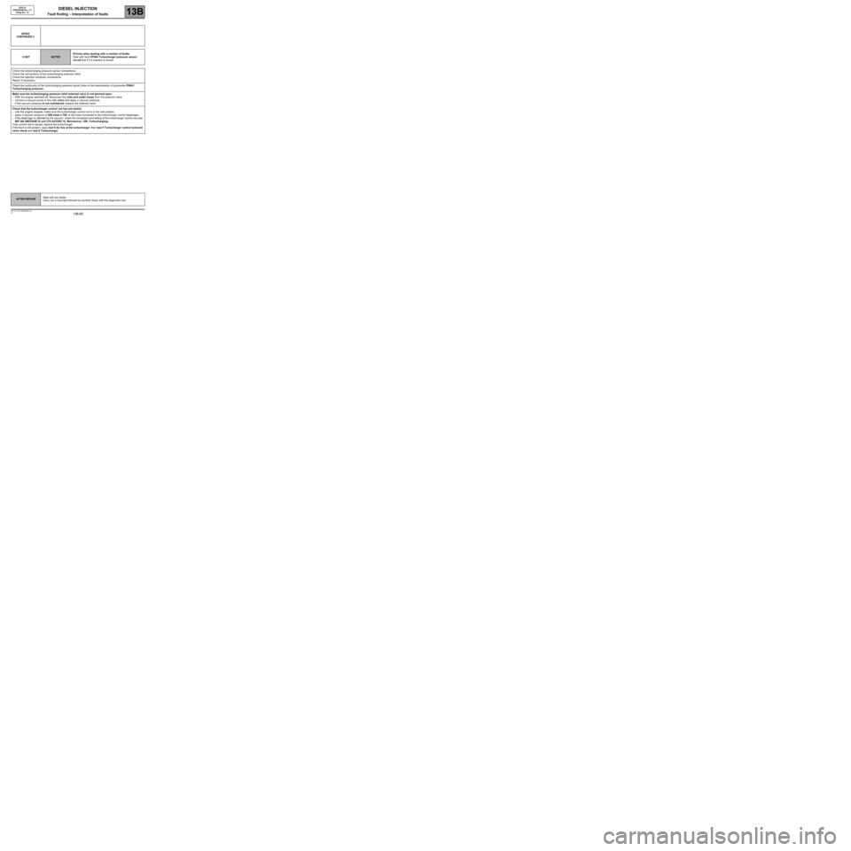
DF055
CONTINUED 2
2.DEF
NOTESPriority when dealing with a number of faults:
Deal with fault DF004 Turbocharger pressure sensor
circuit first if it is present or stored.
Check the turbocharging pressure sensor connections,
Check the connections of the turbocharging solenoid valve,
Check the injection computer connections.
Repair if necessary.
Check the conformity of the turbocharging pressure signal (refer to the interpretation of parameter PR041
Turbocharging pressure).
Make sure the turbocharging pressure relief solenoid valve is not jammed open:
–With the engine switched off, disconnect the inlet and outlet hoses from the solenoid valve.
–connect a vacuum pump to the inlet union and apply a vacuum pressure.
–if the vacuum pressure is not maintained: replace the solenoid valve.
Check that the turbocharger control rod has not seized:
–with the engine stopped, make sure the turbocharger control rod is in the rest position.
–apply a vacuum pressure of 800 mbar ± 100, to the hose connected to the turbocharger control diaphragm,
–if the diaphragm is affected by the vacuum, check the movement and setting of the turbocharger control rod (see
MR 364 (MEGANE II) and 370 (SCENIC II), Mechanical, 12B, Turbocharging).
If the control rod is seized, replace the turbocharger.
If the fault is still present, apply test 9 Air line at the turbocharger, then test 5 Turbocharger control solenoid
valve check and test 6 Turbocharger.
AFTER REPAIRDeal with any faults.
Carry out a road test followed by another check with the diagnostic tool.
Page 96 of 273
DIESEL INJECTION
Fault finding – Interpretation of faults13B
13B-96V3 MR-372-J84-13B250$405.mif
EDC16
PROGRAM No.: C1
Vdiag No.: 51
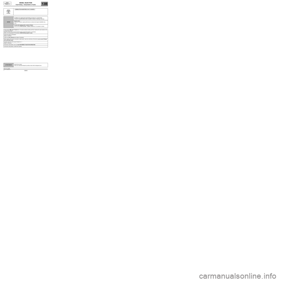
DF059
PRESENT
OR
STOREDCOMBUSTION MISFIRES ON CYLINDER 1
NOTESConditions for applying the fault finding procedure to a stored fault:
The fault is declared present after the engine is started or following a road test.
Special notes:
If the fault is present, engine performance is reduced and engine instabilities may
occur.
Priority when dealing with a number of faults:
Deal with fault DF040 Cylinder 1 injector circuit first, if it is present or stored.
Check that the IMA code of injector no. 1 has been entered correctly and that it matches the code marked on the
corresponding injector.
Enter the code to the unprogrammed/incorrectly programmed injector, if necessary.
Refer to the interpretation of commands, SC002 Entering injector codes.
Check the engine compression.
Repair if necessary.
Check the valve clearance and adjust if necessary.
When dealing with several combustion misfire faults, check the conformity of the fuel by applying test 10 Diesel
fuel conformity check.
Visually inspect the return pipe of injector no. 1.
Repair if necessary.
If the fault is still present, carry out test 8 INCORRECT INJECTOR OPERATION.
If the fault is still present, contact the Techline.
AFTER REPAIRDeal with any faults.
Carry out a road test followed by another check with the diagnostic tool.
EDC16_V51_DF059
Page 97 of 273
DIESEL INJECTION
Fault finding – Interpretation of faults13B
13B-97V3 MR-372-J84-13B250$405.mif
EDC16
PROGRAM No.: C1
Vdiag No.: 51
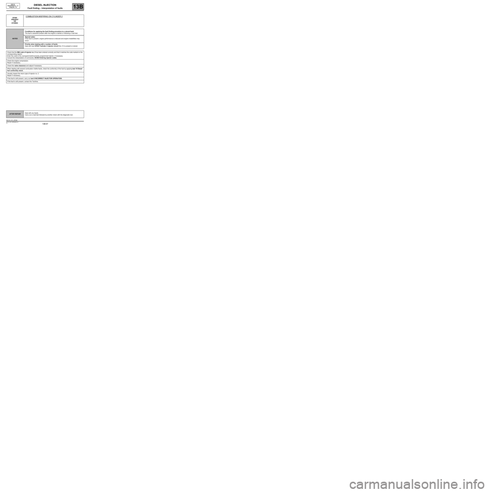
DF060
PRESENT
OR
STOREDCOMBUSTION MISFIRING ON CYLINDER 2
NOTESConditions for applying the fault finding procedure to a stored fault:
The fault is declared present after the engine is started or following a road test.
Special notes:
If the fault is present, engine performance is reduced and engine instabilities may
occur.
Priority when dealing with a number of faults:
Deal with fault DF041 Cylinder 2 injector circuit first, if it is present or stored.
Check that the IMA code of injector no. 2 has been entered correctly and that it matches the code marked on the
corresponding injector.
Enter the code to the unprogrammed/incorrectly programmed injector, if necessary.
Consult the interpretation of commands, SC002 Entering injector codes.
Check the engine compression.
Repair if necessary.
Check the valve clearance and adjust if necessary.
When dealing with several combustion misfire faults, check the conformity of the fuel by applying test 10 Diesel
fuel conformity check.
Visually inspect the return pipe of injector no. 2.
Repair if necessary.
If the fault is still present, carry out test 8 INCORRECT INJECTOR OPERATION.
If the fault is still present, contact the Techline.
AFTER REPAIRDeal with any faults.
Carry out a road test followed by another check with the diagnostic tool.
EDC16_V51_DF060
Page 98 of 273
DIESEL INJECTION
Fault finding – Interpretation of faults13B
13B-98V3 MR-372-J84-13B250$405.mif
EDC16
PROGRAM No.: C1
Vdiag No.: 51
DF061
PRESENT
OR
STOREDCOMBUSTION MISFIRING ON CYLINDER 3
NOTESConditions for applying the fault finding procedure to a stored fault:
The fault is declared present after the engine is started or following a road test.
Special notes:
If the fault is present, engine performance is reduced and engine instabilities may
occur.
Priority when dealing with a number of faults:
Deal with fault DF042 Cylinder 3 injector circuit first, if it is present or stored.
Check that the IMA code of injector no. 3 has been entered correctly and that it matches the code marked on the
corresponding injector.
Enter the code to the unprogrammed/incorrectly programmed injector, if necessary.
Consult the interpretation of commands, SC002 Entering injector codes.
Check the engine compression.
Repair if necessary.
Check the valve clearance and adjust if necessary.
When dealing with several combustion misfire faults, check the conformity of the fuel by applying test 10 Diesel
fuel conformity check.
Visually inspect the return pipe of injector no. 3.
Repair if necessary.
If the fault is still present, carry out test 8 INCORRECT INJECTOR OPERATION.
If the fault is still present, contact the Techline.
AFTER REPAIRDeal with any faults.
Carry out a road test followed by another check with the diagnostic tool.
EDC16_V51_DF061
Page 99 of 273
DIESEL INJECTION
Fault finding – Interpretation of faults13B
13B-99V3 MR-372-J84-13B250$405.mif
EDC16
PROGRAM No.: C1
Vdiag No.: 51
DF062
PRESENT
OR
STOREDCOMBUSTION MISFIRING ON CYLINDER 4
NOTESConditions for applying the fault finding procedure to a stored fault:
The fault is declared present after the engine is started or following a road test.
Special notes:
If the fault is present, engine performance is reduced and engine instabilities may
occur.
Priority when dealing with a number of faults:
Deal with fault DF043 Cylinder 4 injector circuit first, if it is present or stored.
Check that the injector no. 4 IMA code has been entered correctly and that it matches the code marked on the
corresponding injector.
Enter the code to the unprogrammed/incorrectly programmed injector, if necessary.
Consult the interpretation of commands, SC002 Entering injector codes.
Check the engine compression.
Repair if necessary.
Check the valve clearance and adjust if necessary.
When dealing with several combustion misfire faults, check the conformity of the fuel by applying test 10 Diesel
fuel conformity check.
Visually inspect the return pipe of injector no. 4.
Repair if necessary.
If the fault is still present, carry out test 8 INCORRECT INJECTOR OPERATION.
If the fault is still present, contact the Techline.
AFTER REPAIRDeal with any faults.
Carry out a road test followed by another check with the diagnostic tool.
EDC16_V51_DF062
Page 172 of 273
DIESEL INJECTION
Fault finding – Interpretation of statuses13B
13B - 172V3 MR-372-J84-13B250$630.mif
EDC16
PROGRAM NO.: C1
Vdiag No.: 51DIESEL INJECTION
Fault finding – Interpretation of statuses
ET001
COMPUTER + AFTER IGNITION FEED
NOTESSpecial notes:
Only perform these tests if the statuses do not correspond with the system
programming functions.
ABSENT
NOTESIgnition on
Check the condition and conformity of supply fuse F5D (5A) of the Protection and Switching Unit.
Repair if necessary.
Check for an earth on the following connections:
Injection computer black, 32-track connector A,
Track G4Battery earth
Injection computer black 32-track connector A,
Track H4Battery earth
Injection computer black 32-track connector A,
Track H1Battery earth
Repair if necessary.
Check for + 12 V on track D1 of connector A of the injection computer.
If there is no voltage, check the continuity and insulation to earth of the following connection:
Injection computer black 32-track connector A,
track D1Track 1 of the UPC black connector
Repair if necessary.
PRESENT
NOTESIgnition on
Check that there is not a + 12 V with ignition switched off on track D1 of connector A of the injection computer.
Repair if necessary.
AFTER REPAIRCarry out a road test followed by another check with the diagnostic tool.
EDC16_V51_ET001
MR-372-J84-13B250$630.mif
Page 173 of 273
DIESEL INJECTION
Fault finding – Interpretation of statuses13B
13B - 173V3 MR-372-J84-13B250$630.mif
EDC16
PROGRAM NO.: C1
Vdiag No.: 51
ET003
ENGINE IMMOBILISER
NOTESSpecial notes:
Only perform these tests if the statuses do not correspond with the system
programming functions.
ACTIVE
INACTIVE
AFTER REPAIRCarry out a road test followed by a complete test with the diagnostic tool.
EDC16_V51_ET003
(See 87B Passenger compartment connection unit).
(See 87B Passenger compartment connection unit).
Page 174 of 273
DIESEL INJECTION
Fault finding – Interpretation of statuses13B
13B - 174V3 MR-372-J84-13B250$630.mif
NO
EDC16
PROGRAM NO.: C1
Vdiag No.: 51
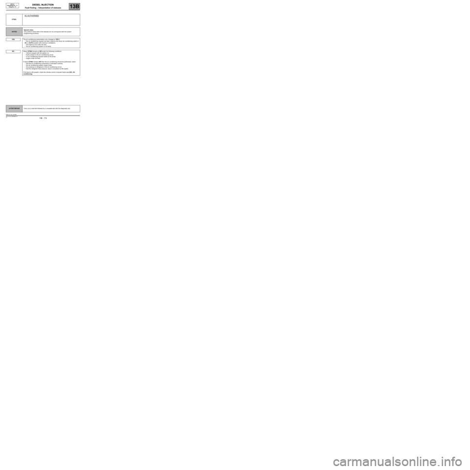
ET004
AC AUTHORISED
NOTESSpecial notes:
Only perform these tests if the statuses do not correspond with the system
programming functions.
YES
The air conditioning authorisation only changes to YES if:
–the air conditioning request has been made by the driver (air conditioning switch in
AC or AUTO position with minimum ventilation),
–the engine is not under full load,
–the air conditioning system is not faulty.
Status ET004 remains at NO under the following conditions:
–Vehicle stopped with the ignition on,
–faults present in the air conditioning circuit,
–no air conditioning request made by the driver,
–engine under full load.
If status ET004 remains NO then the air conditioning should be authorised; check:
–that the air conditioning compressor is activated correctly,
–the air conditioning system supply fuses,
–the presence of refrigerant in the air conditioning circuit,
–that the refrigerant fluid pressure value is consistent at idle speed.
If the fault is still present, check the climate control computer faults (see 62C, Air
conditioning).
AFTER REPAIRCarry out a road test followed by a complete test with the diagnostic tool.
EDC16_V51_ET004
Page 175 of 273
DIESEL INJECTION
Fault finding – Interpretation of statuses13B
13B - 175V3 MR-372-J84-13B250$630.mif
NO
EDC16
PROGRAM NO.: C1
Vdiag No.: 51
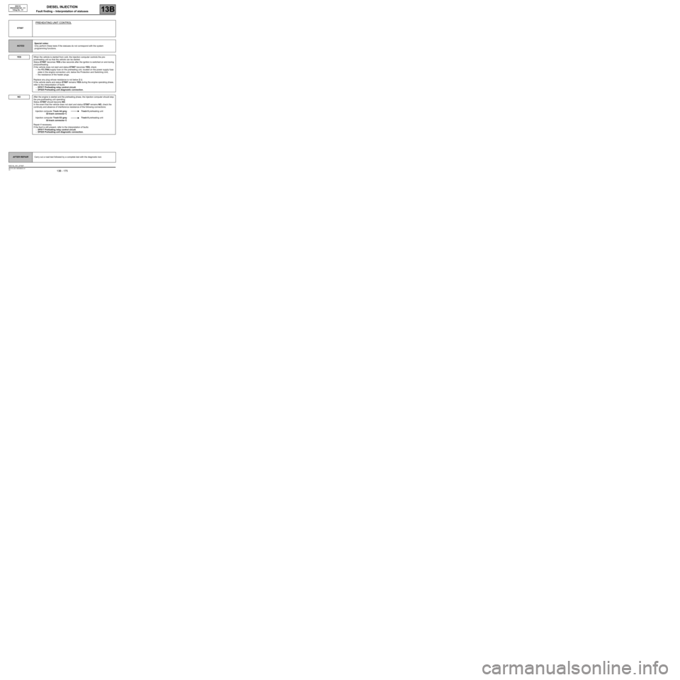
ET007
PREHEATING UNIT CONTROL
NOTESSpecial notes:
Only perform these tests if the statuses do not correspond with the system
programming functions.
YES
When the vehicle is started from cold, the injection computer controls the pre-
postheating unit so that the vehicle can be started.
Status ET007 becomes YES a few seconds after the ignition is switched on and during
pre/postheating.
If the vehicle does not start and status ET007 becomes YES, check:
–the F2 (70A) supply fuse on the preheating unit, located on the power supply fuse
plate in the engine connection unit, below the Protection and Switching Unit,
–the resistance of the heater plugs.
Replace any plug whose resistance is not below 2 Ω.
If the vehicle starts and status ET007 remains YES during the engine operating phase,
refer to the interpretation of faults:
–DF017 Preheating relay control circuit.
–DF025 Preheating unit diagnostic connection.
After the engine is started and the preheating phase, the injection computer should stop
the pre-postheating unit operating.
Status ET007 should become NO.
In the event that the vehicle does not start and status ET007 remains NO, check the
continuity and absence of interference resistance of the following connections:
Injection computer Track A4 grey
32-track connector CTrack 9 preheating unit
Injection computer Track E2 grey
32-track connector CTrack 8 preheating unit
Repair if necessary.
If the fault is still present, refer to the interpretation of faults:
–DF017 Preheating relay control circuit.
–DF025 Preheating unit diagnostic connection.
AFTER REPAIRCarry out a road test followed by a complete test with the diagnostic tool.
EDC16_V51_ET007