brake RENAULT SCENIC 2009 J84 / 2.G Engine And Peripherals EDC16 User Guide
[x] Cancel search | Manufacturer: RENAULT, Model Year: 2009, Model line: SCENIC, Model: RENAULT SCENIC 2009 J84 / 2.GPages: 273
Page 167 of 273
DIESEL INJECTION
Fault finding – Conformity check13B
13B - 167V3 MR-372-J84-13B250$540.mif
EDC16
PROGRAM NO.: C1
Vdiag No.: 51
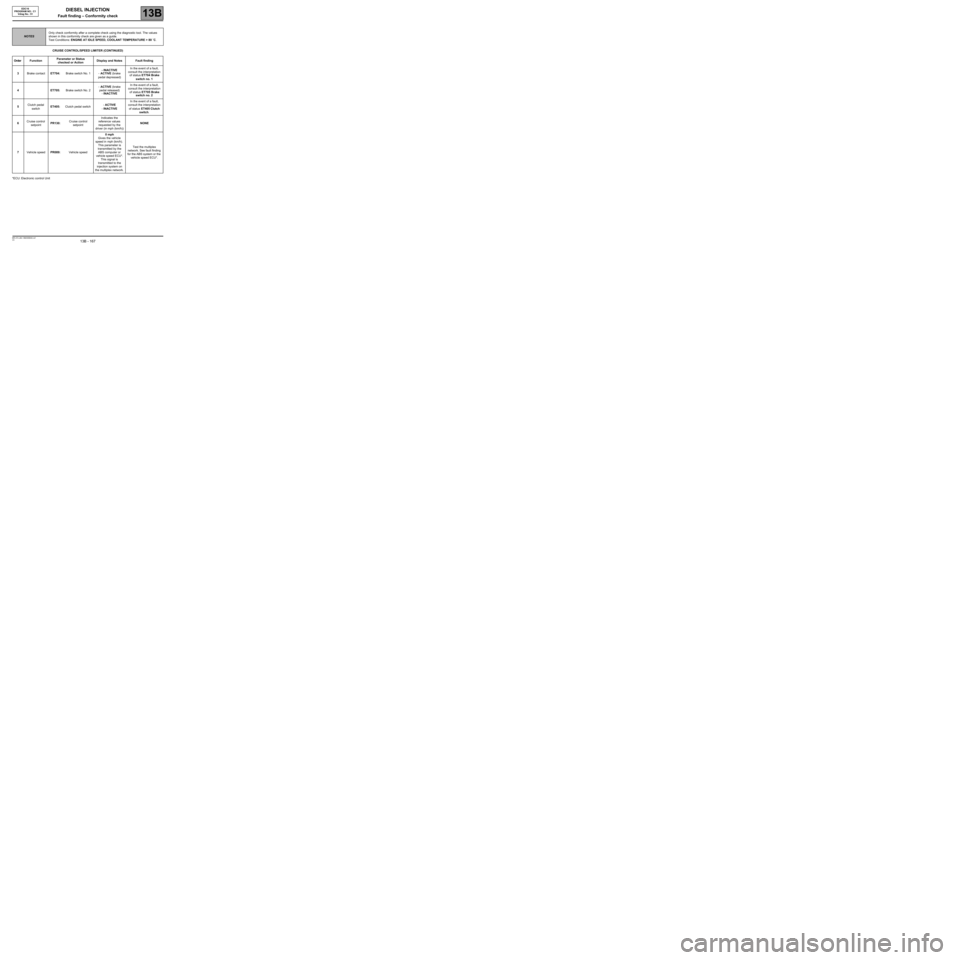
CRUISE CONTROL/SPEED LIMITER (CONTINUED)
*ECU: Electronic control Unit
NOTESOnly check conformity after a complete check using the diagnostic tool. The values
shown in this conformity check are given as a guide.
Test Conditions: ENGINE AT IDLE SPEED, COOLANT TEMPERATURE > 80 ˚C.
Order FunctionParameter or Status
checked or ActionDisplay and Notes Fault finding
3Brake contactET704:Brake switch No. 1- INACTIVE
- ACTIVE (brake
pedal depressed)In the event of a fault,
consult the interpretation
of status ET704 Brake
switch no. 1
4ET705: Brake switch No. 2- ACTIVE (brake
pedal released)
- INACTIVEIn the event of a fault,
consult the interpretation
of status ET705 Brake
switch no. 2
5Clutch pedal
switchET405:Clutch pedal switch- ACTIVE
- INACTIVEIn the event of a fault,
consult the interpretation
of status ET405 Clutch
switch.
6Cruise control
setpointPR130:Cruise control
setpointIndicates the
reference values
requested by the
driver (in mph (km/h))NONE
7Vehicle speedPR089:Vehicle speed0 mph
Gives the vehicle
speed in mph (km/h).
This parameter is
transmitted by the
ABS computer or
vehicle speed ECU*.
This signal is
transmitted to the
injection system on
the multiplex network.Test the multiplex
network. See fault finding
for the ABS system or the
vehicle speed ECU*.
Page 168 of 273
DIESEL INJECTION
Fault finding – Conformity check13B
13B - 168V3 MR-372-J84-13B250$540.mif
EDC16
PROGRAM NO.: C1
Vdiag No.: 51
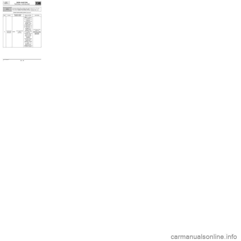
CRUISE CONTROL/SPEED LIMITER (continued 2)
NOTESOnly check conformity after a complete check using the diagnostic tool. The values
shown in this conformity check are given as a guide.
Test Conditions: ENGINE AT IDLE SPEED, COOLANT TEMPERATURE > 80 ˚C.
Order FunctionParameter or Status
checked or ActionDisplay and Notes Fault finding
8Cruise control/
speed limiter
deactivationET415:Cruise control/speed
limiter
deactivationNONE: This status is
present on the diagnostic
tool when:
The computer has been
reinitialised.
The computer has been
reprogrammed.
- STATUS 1: Traction
control request
- STATUS 2: Brake pedal
depressed.
- STATUS 3: Clutch pedal
depressed.
- STATUS 4: Cancel
button pressed
- STATUS 5: Cruise
control or speed limiter
monitoring.
- STATUS 6: Gear lever
in neutral (manual
gearbox) or neutral
position (automatic
transmission).
- STATUS 7:
Inconsistency between
the request and the
vehicle speed.
- STATUS 8: Automatic
transmission in defect
mode.
- STATUS 9: Vehicle
speed monitoring.
- STATUS 10: Monitoring
by injection computer.In the event of a fault,
consult the
interpretation of status
ET415 Cruise control/
speed limiter
deactivation.
Page 171 of 273
DIESEL INJECTION
Fault finding – Status summary table13B
13B - 171V3 MR-372-J84-13B250$585.mif
EDC16
PROGRAM NO.: C1
Vdiag No.: 51DIESEL INJECTION
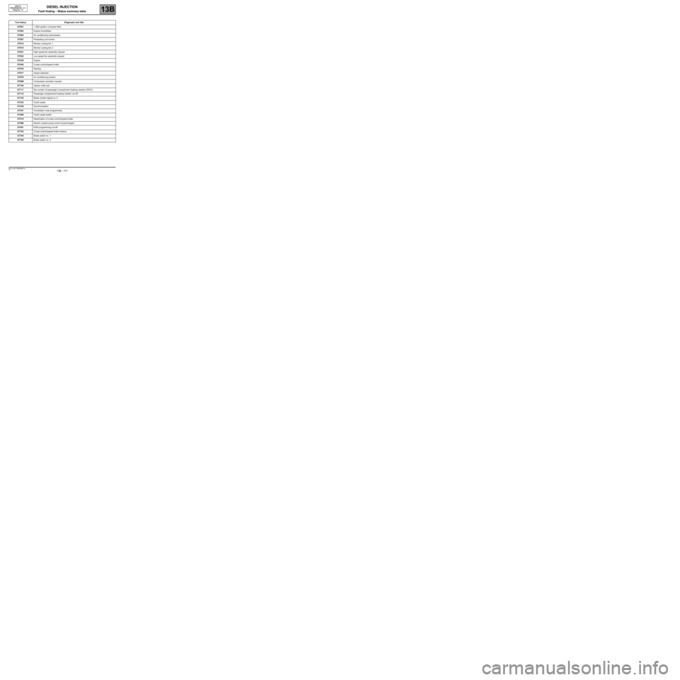
Fault finding – Status summary table
Tool status Diagnostic tool title
ET001+ After ignition computer feed
ET003Engine immobiliser
ET004Air conditioning authorisation
ET007Preheating unit control
ET014Monitor cooling fan 1
ET015Monitor cooling fan 2
ET021High speed fan assembly request
ET022Low speed fan assembly request
ET038Engine
ET042Cruise control/speed limiter
ET076Starting
ET077Impact detected
ET079Air conditioning present
ET088Compressor actuation request
ET104Injector code use
ET111Set number of passenger compartment heating resistors (RCH)
ET112Passenger compartment heating resistor cut-off
ET123Brake contact signal no. 2
ET233Clutch pedal
ET238Synchronisation
ET341Immobiliser code programmed
ET405Clutch pedal switch
ET415Deactivation of cruise control/speed limiter
ET589Electric coolant pump control (turbocharger)
ET651EGR programming cut-off
ET703Cruise control/speed limiter buttons
ET704Brake switch no. 1
ET705Brake switch no. 2
MR-372-J84-13B250$585.mif
Page 195 of 273
DIESEL INJECTION
Fault finding – Interpretation of statuses13B
13B - 195V3 MR-372-J84-13B250$630.mif
STATUS 3
EDC16
PROGRAM NO.: C1
Vdiag No.: 51
ET415
1(CONTINUED)
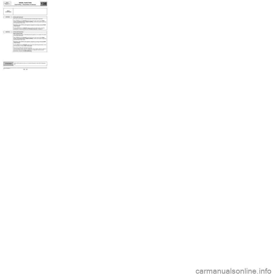
STATUS 2
Brake pedal depressed
The cruise control function is deactivated when the brake pedal is depressed.
Status ET415 becomes STATUS 2 when driving with cruise control active (ET042
Cruise control/Speed limiter: CRUISE CONTROL) and the brake pedal is depressed.
This deactivates cruise control.
Reinitialise status ET415 on the injection computer by running command RZ007
“Fault memory”.
If status ET415 becomes STATUS 2 without pressing the brake pedal, consult the
interpretation of statuses ET704 and ET705 Brake contact No. 1 and No. 2.
Clutch pedal depressed
Manual gearbox ONLY
The cruise control function is deactivated when the gearbox is not coupled to the engine
(clutch pedal depressed).
Status ET415 becomes STATUS 3 when driving with cruise control active (ET042
Cruise control/speed limiter: CRUISE CONTROL) and the clutch pedal is depressed.
This deactivates cruise control.
Reinitialise status ET415 on the injection computer by running command RZ007
“Fault memory”.
If status ET415 becomes STATUS 3 without the clutch pedal being depressed, consult
the interpretation of status ET405: Clutch pedal.
If the vehicle is fitted with automatic transmission:
Test the multiplex network: check the configuration of the multiplex network in relation to
the vehicle's technical specification, especially the configuration of the automatic
transmission computer (see 88B, Multiplexing)
AFTER REPAIRSwitch off the ignition and carry out a road test followed by a test with the diagnostic
tool.
1
Page 196 of 273
DIESEL INJECTION
Fault finding – Interpretation of statuses13B
13B - 196V3 MR-372-J84-13B250$630.mif
EDC16
PROGRAM NO.: C1
Vdiag No.: 51
1
STATUS 5
ET415
(CONTINUED 2)
STATUS 4
Cancel button pressed
The cruise control/speed limiter function is deactivated each time the suspend button is
pressed.
Status ET415 becomes STATUS 4 while driving when:
- Either the cruise control is active, or
- the speed limiter is active
- and the driver presses the 0 button.
This action deactivates the Cruise control/Speed limiter.
Reinitialise status ET415 on the injection computer by running command RZ007
“Fault memory”.
If status ET415 becomes STATUS 4 without pressing the 0 button, refer to the
interpretation of status ET703 Cruise control/speed limiter buttons and test the R/0
control button located on the steering wheel, to the right.
Cruise control or speed limiter monitoring
This status appears when the vehicle brakes or decelerates sharply without the injection
computer receiving a signal indicating that the brake pedal switch has been pressed.
If status ET415 is STATUS 5, refer to the interpretation of:
- status ET042 Cruise control/Speed limiter,
- status ET703 Cruise control/speed limiter buttons,
- status ET704 Brake contact no. 1,
- and status ET705 Brake contact No 2,
to test the cruise control/speed limiter system components and find the defective
component.
Also check the operation of the accelerator pedal, and check for any faults on the
diagnostic tool relating to this component. Deal with them if necessary.
Reinitialise status ET415 on the injection computer by running command RZ007
“Fault memory”.
If status ET415 changes to STATUS 5, deal with present faults or those stored in the
injection computer.
If the fault is still present, contact Techline.
AFTER REPAIRSwitch off the ignition and carry out a road test followed by a test with the diagnostic
tool.
Page 205 of 273
DIESEL INJECTION
Fault finding – Interpretation of statuses13B
13B - 205V3 MR-372-J84-13B250$630.mif
EDC16
PROGRAM NO.: C1
Vdiag No.: 51
ET704
ET705
BRAKE CONTACT No. 1
BRAKE CONTACT No. 2
NOTESSpecial note:
Only perform the tests if the statuses do not correspond with the system programming
functions.
Note:
Statuses ET704 and ET705 should change at the same time. If they are not consistent, refer to the interpretation
of fault DF050 Brake switch circuit.
ACTIVE
or
INACTIVEIf the brake lights are working:
–check the continuity and make sure there is no interference resistance on the
following connection:
●connection code 5A,
between components 160 and 120/645/119.
If there is a repair method (See Technical Note 6015A, Repairing electrical wiring,
Wiring: Precautions for repair), repair the wiring, otherwise replace the wiring.
If the brake lights are not operational, check:
–the condition and fitting of the brake switch,
–the condition and conformity of the brake lights fuse,
–the conformity of the values in the following table:
disconnect the switch and carry out the following checks:
for MEGANE II and SCENIC II with ESP:
Continuity between
connectionsInsulation between
connections
Switch engaged
(Brake pedal released)5A and BPT 65G and SP17
Switch released
(Brake pedal depressed)65G and SP17 5A and BPT
For MEGANE II and SCENIC II without ESP
Continuity between
connectionsInsulation between
connections
Switch engaged
(Brake pedal released)5A and BPT 65A and SP17
Switch released
(Brake pedal depressed)65G and SP17 5A and BPT
AFTER REPAIRSwitch off the ignition and carry out a road test followed by a test with the diagnostic
tool.
EDC16_V51_ET704/EDC16_V51_ET705
Page 229 of 273
DIESEL INJECTION
Fault finding – Fault Finding Chart13B
13B -229V3 MR-372-J84-13B250$855.mif
ALP4
CONTINUED
Is the engine running on all cylinders?
NO
Check the operation of the injectors: apply test 8 Incorrect injector
operation.
If the fault is still present
Check the conformity of the accelerator pedal position sensor, the brake pedal sensor, the atmospheric pressure
sensor, the exhaust gas recirculation valve and the damper valve.
–Check the consistency of the signal: of the air flowmeter, of the engine coolant temperature sensor, of the fuel
temperature sensor and of the engine speed.
Check the connections, continuity and absence of interference resistance on the air flow sensor (apply DF056 Air
flow sensor circuit, 2.def), the engine coolant temperature sensor (apply DF001 Coolant circuit, 1.def), and the
engine speed (apply DF195 Camshaft sensor/engine speed consistency, 2.def).
Check: – That the diesel filter is not clogged (for the test, see DF053 Rail pressure regulation function
2.def).
–That there are no leaks on the high and low pressure diesel circuits: apply test 3 Turbocharged
air inlet circuit check.
–That the oil vapour rebreathing system is connected.
–The flow regulator (blocked/seized, apply the interpretation for command: AC011 Rail pressure
regulator).
–Check the timing setting (and the position of the high pressure pump sprocket) (see MR 364 (MEGANE II) or
370 (SCENIC II), Mechanical, 11A, Top and front of engine).
–Check the cylinder compressions (balance of the cylinder compressions with the Compression test function
on the CLIP Technic diagnostic tool).
–Measure the engine compressions using the special tool.
If the fault is still present, contact the Techline.YES
EDC16
PROGRAM No.: C1
Vdiag No.: 51
AFTER REPAIRcarry out a road test followed by a complete check with the diagnostic tool.
Page 230 of 273
DIESEL INJECTION
Fault finding – Fault Finding Chart13B
13B -230V3 MR-372-J84-13B250$855.mif
EDC16
PROGRAM No.: C1
Vdiag No.: 51
ALP5 Irregular engine operation
NOTESBefore dealing with this customer complaint, check that there are no faults, and
the conformity (or otherwise) of the parameters and statuses using the
diagnostic tool.
If the customer complaint is not ironed out, perform the following checks:
If the engine races during gear changes, check, if there is a floor carpet, that this is not blocking the accelerator
pedal, the brake pedal or the clutch pedal, then check the conformity of the clutch switch and the conformity of the
accelerator pedal sensor when the pedal is released.
Measure the resistance of the engine speed sensor between terminals A and B of its black connector.
If the winding resistance is not between 510 Ω and 850 Ω at an engine temperature of 20˚C, replace the engine
speed sensor.
Check the continuity of the following connections:
–engine management computer, connector B track B1 track A of the engine speed sensor
–engine computer, connector B track C1 track B of the engine speed sensor
Check the conformity of the engine earths (oxidation, tightness, etc.).
Check the mounting, the air gap (check that the engine speed sensor - flywheel gap is 0.5 to 1.8 mm) and the
condition of the sensor (heating).
Replace if necessary.
Check the low pressure circuit.
–Check the pressure regulation solenoid valve by applying section B of the Rough idle fault finding chart.
~ 1600 bar with full load on the accelerator.
–Apply the procedure for checking the air flow; see conformity check.
–Check the turbocharger: apply test 9 Air line at the turbocharger, then test 5 Turbocharger control solenoid
valve check and test 6 Turbocharger.
–Apply the procedure for checking the hydraulic circuit see conformity check.
If the fault is still present:
–Check the balance of the cylinders using the CLIP Technic function, Compression test physical measurements
icon.
–Check the cylinder compressions if necessary using the special tool.
AFTER REPAIRcarry out a road test followed by a complete check with the diagnostic tool.
EDC16_V51_ALP5