ECU RENAULT SCENIC 2009 J84 / 2.G Engine And Peripherals EDC16 Owner's Manual
[x] Cancel search | Manufacturer: RENAULT, Model Year: 2009, Model line: SCENIC, Model: RENAULT SCENIC 2009 J84 / 2.GPages: 273
Page 167 of 273

DIESEL INJECTION
Fault finding – Conformity check13B
13B - 167V3 MR-372-J84-13B250$540.mif
EDC16
PROGRAM NO.: C1
Vdiag No.: 51
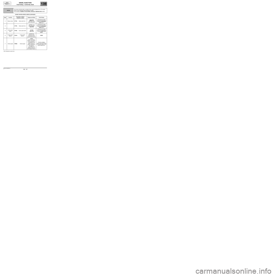
CRUISE CONTROL/SPEED LIMITER (CONTINUED)
*ECU: Electronic control Unit
NOTESOnly check conformity after a complete check using the diagnostic tool. The values
shown in this conformity check are given as a guide.
Test Conditions: ENGINE AT IDLE SPEED, COOLANT TEMPERATURE > 80 ˚C.
Order FunctionParameter or Status
checked or ActionDisplay and Notes Fault finding
3Brake contactET704:Brake switch No. 1- INACTIVE
- ACTIVE (brake
pedal depressed)In the event of a fault,
consult the interpretation
of status ET704 Brake
switch no. 1
4ET705: Brake switch No. 2- ACTIVE (brake
pedal released)
- INACTIVEIn the event of a fault,
consult the interpretation
of status ET705 Brake
switch no. 2
5Clutch pedal
switchET405:Clutch pedal switch- ACTIVE
- INACTIVEIn the event of a fault,
consult the interpretation
of status ET405 Clutch
switch.
6Cruise control
setpointPR130:Cruise control
setpointIndicates the
reference values
requested by the
driver (in mph (km/h))NONE
7Vehicle speedPR089:Vehicle speed0 mph
Gives the vehicle
speed in mph (km/h).
This parameter is
transmitted by the
ABS computer or
vehicle speed ECU*.
This signal is
transmitted to the
injection system on
the multiplex network.Test the multiplex
network. See fault finding
for the ABS system or the
vehicle speed ECU*.
Page 223 of 273

DIESEL INJECTION
Fault finding – Fault Finding Chart13B
13B -223V3 MR-372-J84-13B250$855.mif
EDC16
PROGRAM No.: C1
Vdiag No.: 51DIESEL INJECTION
Fault finding – Fault Finding Chart
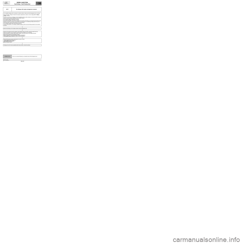
ALP1 No dialogue with engine management computer
Try to establish dialogue with a computer on another vehicle to make sure that the diagnostic tool is not faulty.
Check the battery voltage and make the necessary adjustments to obtain a correct voltage (9.5 V < Battery
voltage < 17.5 V).
If the tool is not at fault, and dialogue cannot be established with any other computer on the same vehicle, the cause
could be a faulty computer interfering on the multiplex network.
disconnect the engine management computer.
try to establish dialogue with another computer.
if the fault is still present, reconnect the computer and proceed by elimination by successively disconnecting all the
following computers (according to wiring diagram and equipment): air conditioning, airbag, abs and esp, uch,
instrument panel, central communication unit, proximity sensor.
Try to establish dialogue after disconnecting each line:
if, after a disconnection, you manage to establish dialogue, perform the fault finding procedure for the relevant
computer.
perform fault finding on the multiplex network using the diagnostic tool.
Check for the presence and the condition of the injection fuses on the UPC, and/or the engine fuse box.
check the connection of the computer connectors and the condition of its connections.
Check the injection computer earths (quality, oxidation, earth bolts secure on the battery terminal).
Check that the supply to the computer is correct:
Earth on tracks H1, G4 and H4 of black 32-track connector A.
+ after ignition feed on track D1 of black 32 track connector A.
Check that the power supply to the diagnostic socket is correct:
+ before ignition feed on track 16.
+ after ignition feed on track 1.
Earth on tracks 4 and 5.
If dialogue has still not been established after these checks, contact the techline.
AFTER REPAIRCarry out a road test followed by a complete check with the diagnostic tool.
EDC16_V51_ALP1
Page 259 of 273

DIESEL INJECTION
Fault finding – Test13B
13B -259V3 MR-372-J84-13B250$900.mif
TEST8
CONTINUED 2
IMPORTA NT
When removing and refitting an injector, follow the cleanliness guidelines and safety advice (seeMR 364 (Mégane
II) or 370 (Scénic II), Mechanical systems 13B, Diesel injector: Removal - R efitting).
Section B: Conf irmation of flow corre ction fault finding for each inje ctor (individua l c orre ction):
Cle ar the faultsandperform a test wi th theengine idlingfor at l east5minutes,fueltemperature>50˚C.
Ch eck th at n o fault a p p e a r s o n t heCLIPdiagnostic tooland that the corrective values do not reach±5mg/stroke
to confirm therepair.
Ifthecustomer complaint is still present and the fuel flow correction values are all between-5mg/stroke a nd + 5
mg/strok e,applyPartAFuel regulation balanc e che ck f or each injector (individual)of this test (CAS Eno. 4).
If one or more cylinders has injector flow correction values in excess of±5 mg/stroke,applyPart AFuel re gulation
ba lance c heck for each inj e c t or(individu a l ),asoneormoreadditional injectors may be defective.
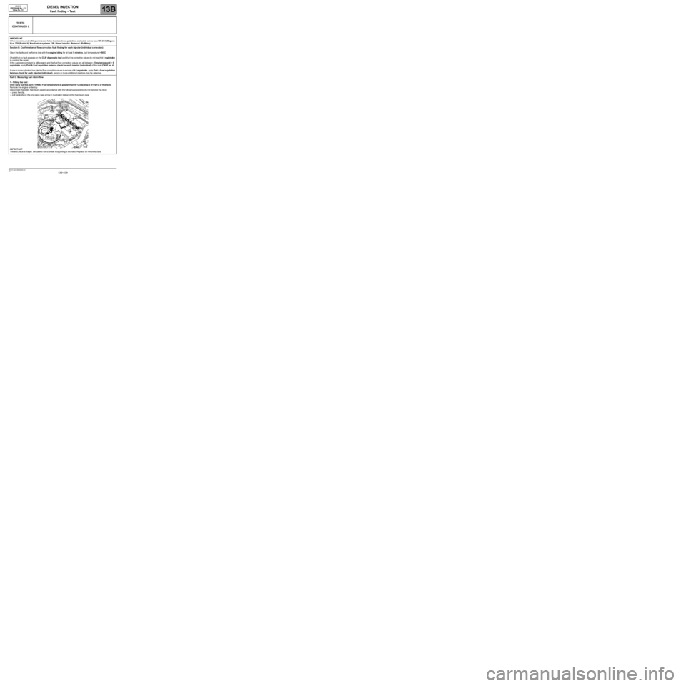
Part C: Measuring fuelreturnflow
1-Fitting the tool:
Only carryout this pa rt if PR063 Fuel t empera ture is greater t han 50˚C (see step 2 of Part C of this test).
Remove the engine undertray
Disco nnect the entire fuel return pipe in accordance with the foll owing procedure (do not remove the clips):
–pressthe clip ,
–pullvertically on the end piece ( see arrow in i llustration below) of the fuel return pipe.
IMPORTANT
The end piece is fragile. Be careful not to break it by pulling it too hard. Replace all removed clips
EDC16
PROGRAM No.: C1
Vdiag No.: 51