air filter RENAULT SCENIC 2009 J84 / 2.G Engine And Peripherals EDC16 Owner's Manual
[x] Cancel search | Manufacturer: RENAULT, Model Year: 2009, Model line: SCENIC, Model: RENAULT SCENIC 2009 J84 / 2.GPages: 273
Page 252 of 273

DIESEL INJECTION
Fault finding – Test13B
13B -252V3 MR-372-J84-13B250$900.mif
EDC16
PROGRAM No.: C1
Vdiag No.: 51
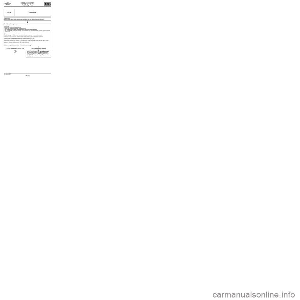
TEST6 Turbocharger
IMPORTANT
Perform these checks without removing the turbocharger and with the vehicle ignition switched off.
Check the turbocharger shaft
WARNING
Respect the following safety precautions:
–wear heat resistant gloves when the engine is hot,
–do not wear loose or baggy clothing and do not wear loose hanging jewellery,
–be aware that the cooling fan assembly may be triggered and pay attention to the operation of the accessories
belt or belts.
Note:
The turbocharger shaft is the shaft connecting the compressor wheel and the turbine wheel.
According to the vehicle type, maximum visual access will either be from above or from below.
Disconnect the air pipe located between the turbocharger and the air filter.
Wearing gloves, check the operation of the turbocharger shaft by turning the vanes manually without forcing.
Is there a point of resistance when the shaft is rotated?
Does the compressor wheel touch the turbocharger housing?
If for these 2 questions the response is NOIf YES for one of these 2 questions
Replace the turbocharger (see MR 364 (Mégane II) or
370 (Scénic II), Mechanical, 12B, Turbocharging,
Turbocharger: Removal - Refitting and Technical
Note 3938A, Broken turbocharger: Replacement
instructions).
EDC16_V51_TEST6
Page 264 of 273

DIESEL INJECTION
Fault finding – Test13B
13B -264V3 MR-372-J84-13B250$900.mif
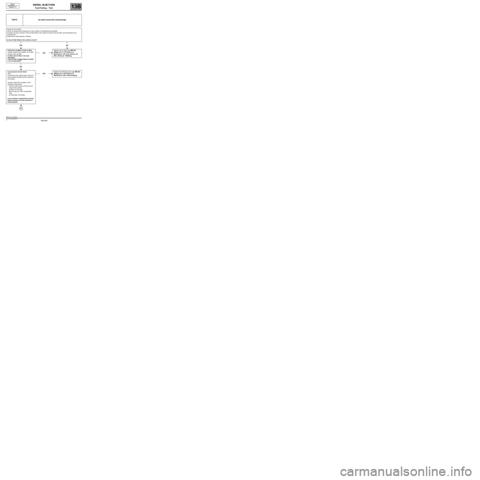
TEST9 Air path around the turbocharger
Check for the air filter
Check the replacement frequency for the air filter in the Maintenance Booklet.
Compare the part numbers of the air filter fitted to the vehicle and that of the air filter recommended by the
manufacturer.
Check the air filter direction of fitting.
Is the air filter fitted to the vehicle correct?
YES NO
Check the condition of the air filter
Visually inspect the condition of the filter
section of the air filter.
Is either the air filter or its seal
damaged?
Is the air filter clogged (does it contain
a lot of impurities)?YESReplace the air filter (see MR 364
(Mégane II) or 370 (Scénic II),
Mechanical, 12A, Fuel mixture, Air
filter, Removal - Refitting).
NO
Low pressure circuit check
Note:
According to the vehicle type, maximum
visual access will either be from above or
from below.
Visually inspect the condition of the
following components:
–fresh air inlet scoop on the front end
panel of the vehicle,
–air filter air inlet pipe,
–filter air pipe up to the compressor
inlet,
–air flowmeter mountings.
Is one of these components incorrect
(disconnected, cut, bent, pierced or
kinked pipes)?YESReplace the defective parts (see MR 364
(Mégane II) or 370 (Scénic II),
Mechanical, 12B, Turbocharging).
EDC16
PROGRAM No.: C1
Vdiag No.: 51
EDC16_V51_TEST9
Page 266 of 273

DIESEL INJECTION
Fault finding – Test13B
13B -266V3 MR-372-J84-13B250$900.mif
EDC16
PROGRAM No.: C1
Vdiag No.: 51
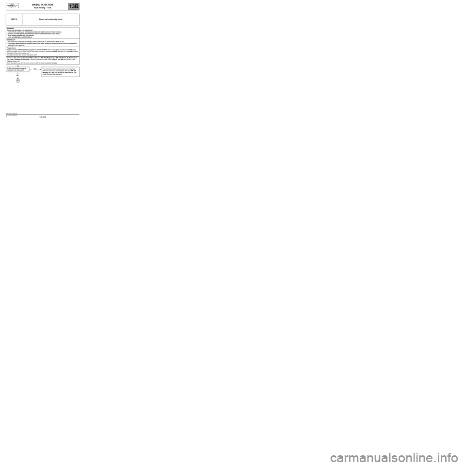
TEST10 Diesel fuel conformity check
WARNING
During t hisop eration, it is essential t o:
–refrain from smoking or bringing incandescent objects close to the work area,
–protect yourself against fuel splashes due to residual pressure in the pipes,
–wear safety goggles with side guards,
–wear leaktight gloves (Nitrile type).
IMPORTA NT
–To avoid any corrosion or damage, protect the areas on which fuel is likely to run.
–To prevent impurities from entering the circuit, place protective plugs on all fuel circuit components
exposed to the open air.
Preparations:
Weigh an empty 1300 ml plastic cup (part no. 77 11 171 413) with its cover (part no. 77 11 171 416) using
electronic scales such as those used in body paint workshops (example: PANDA part no. 77 11 224 995). Record
the weight of the empty plastic cup.
This type of plastic cup is used to prepare paint.
Remove 1 litre of fuel at the diesel filter outlet (see MR 364 (Mégane II) or MR 370 (Scénic II), Mechanical,
19C, Tank, Draining the fuel tank), using a pneumatic transfer pump (part no. 634-200) and place it in the
1300 ml plastic cup.
Cover the plastic cup with its cover and let it settle for approximately 2 minutes.
Is the fuel cloudy or does it
separate into two parts?YESThe diesel fuel contains water and is not compliant.
Drain the fuel circuit, including the tank (see MR 364
(Mégane II) or MR 370 (Scénic II), Mechanical, 19C,
Tank, Draining the fuel tank).
NO
EDC16_V51_TEST10
Page 273 of 273

DIESEL INJECTION
Fault finding – Glossary13B
13B -273V3 MR-372-J84-13B250$945.mif
EDC16
PROGRAM No.: C1
Vdiag No.: 51DIESEL INJECTION
Fault finding – Glossary
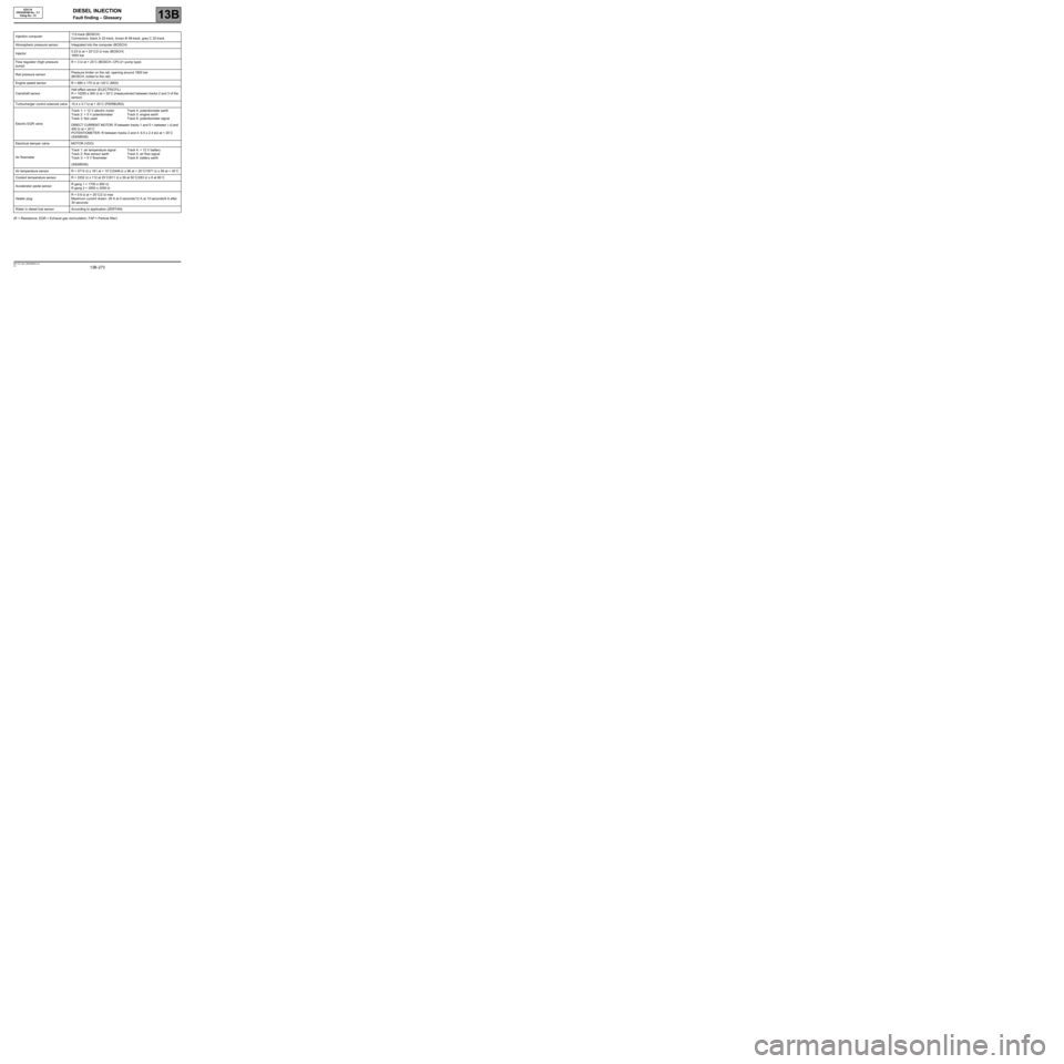
(R = Resistance, EGR = Exhaust gas recirculation, FAP = Particle filter)Injection computer112-track (BOSCH)
Connectors: black A 32-track, brown B 48-track, grey C 32-track
Atmospheric pressure sensor Integrated into the computer (BOSCH)
Injector0.23 Ω at + 20˚C/2 Ω max (BOSCH)
1600 bar
Flow regulator (high pressure
pump)R = 3 Ω at + 20˚C (BOSCH, CP3.2+ pump type)
Rail pressure sensorPressure limiter on the rail: opening around 1800 bar
(BOSCH, bolted to the rail)
Engine speed sensor R = 680 ± 170 Ω at +20˚C (MGI)
Camshaft sensorHall effect sensor (ELECTRICFIL)
R = 10250 ± 500 Ω at + 20˚C (measurement between tracks 2 and 3 of the
sensor)
Turbocharger control solenoid valve 15.4 ± 0.7 Ω at + 20˚C (PIERBURG)
Electric EGR valveTrack 1: + 12 V electric motor
Track 2: + 5 V potentiometer
Track 3: Not usedTrack 4: potentiometer earth
Track 5: engine earth
Track 6: potentiometer signal
DIRECT CURRENT MOTOR: R between tracks 1 and 5 = between 1 Ω and
400 Ω at + 20˚C
POTENTIOMETER: R between tracks 2 and 4: 6.5 ± 2.4 kΩ at + 20˚C
(SIEMENS)
Electrical damper valve MOTOR (VDO)
Air flowmeterTrack 1: air temperature signal
Track 2: flow sensor earth
Track 3: + 5 V flowmeterTrack 4: + 12 V battery
Track 5: air flow signal
Track 6: battery earth
(SIEMENS)
Air temperature sensor R = 3714 Ω ± 161 at + 10˚C/2448 Ω ± 96 at + 20˚C/1671 Ω ± 59 at + 30˚C
Coolant temperature sensor R = 2252 Ω ± 112 at 25˚C/811 Ω ± 39 at 50˚C/283 Ω ± 8 at 80˚C
Accelerator pedal sensorR gang 1 = 1700 ± 900 Ω;
R gang 2 = 2850 ± 2050 Ω
Heater plugR = 0.6 Ω at + 20˚C/2 Ω max
Maximum current drawn: 28 A at 0 seconds/12 A at 10 seconds/9 A after
30 seconds
Water in diesel fuel sensor According to application (ZERTAN)