torque RENAULT SCENIC 2009 J84 / 2.G Engine And Peripherals EDC16 Workshop Manual
[x] Cancel search | Manufacturer: RENAULT, Model Year: 2009, Model line: SCENIC, Model: RENAULT SCENIC 2009 J84 / 2.GPages: 273
Page 9 of 273
DIESEL INJECTION
Fault finding – System operation13B
13B - 9V3 MR-372-J84-13B250$135.mif
EDC16
PROGRAM No: C1
Vdiag No.: 51DIESEL INJECTION
Fault finding – System operation
System outline
The high pressure injection system is designed to deliver a precise quantity of diesel fuel to the engine at a set
moment.
It is fitted with a 112-track BOSCH EDC16 C3 type computer.
The system is comprised of:
–a priming bulb on the low pressure circuit,
–a diesel filter,
–a high pressure pump with a built-in low pressure pump (transfer pump),
–a high pressure regulator mounted on the pump,
–an injector rail,
–a diesel fuel pressure sensor built into the rail,
–four solenoid injectors,
–a coolant temperature sensor,
–a cylinder reference sensor,
–an engine speed sensor,
–a turbocharger pressure sensor,
–an accelerator pedal potentiometer,
–an EGR solenoid valve,
–an atmospheric pressure sensor integrated into the injection computer,
–an air flow sensor with an air temperature sensor,
–a turbocharging pressure limitation solenoid valve,
–a motorised damper valve.
The common rail direct high pressure injection system works sequentially (based on the petrol engine multipoint
injection).
This injection system reduces operating noise, reduces the volume of pollutant gases and particles and produces
high engine torque at low engine speeds thanks to a pre-injection procedure.
The high pressure pump generates the high pressure and transmits it to the injector rail. The actuator located on the
pump controls the quantity of diesel fuel supplied, according to the requirement determined by the computer. The rail
supplies each injector through a steel pipe.
MR-372-J84-13B250$135.mif
Page 39 of 273
DIESEL INJECTION
Fault finding – Interpretation of faults13B
13B-39V3 MR-372-J84-13B250$315.mif
EDC16
PROGRAM No.: C1
Vdiag No.: 51
DF008
PRESENT
OR
STOREDPEDAL POTENTIOMETER CIRCUIT GANG 1
CO.0 : Open circuit or short circuit to earth
CC.1 : Short circuit to + 12 V
1.DEF : Inconsistency of the signal
2.DEF : Accelerator pedal sensor locked
NOTESConditions for applying the fault finding procedure to stored faults:
The fault is declared present after a series of full-load/no-load actions on the
accelerator pedal.
Special notes:
Turbocharging, Passenger Compartment Heating Resistor activation and cruise
control/speed limiter are not authorised.
If CO.0, CC.1, 1.DEF is present the level 1 warning light is lit.
The engine speed is set at 1,400 rpm if there is a fault on gang 1 and 2 of the pedal
potentiometer and the engine torque is limited.
Use bornier Ele. 1681 or Ele. 1590 for all operations on the computer connectors.
Priorities when dealing with a number of faults:
Deal with fault DF011 Sensor supply voltage no. 1 first if it is present or stored.
WARNING
This fault may appear if the wiring harness has been damaged.
Follow the procedure described in the Wiring Check in the Introduction.
This check enables the condition and the conformity of the engine wiring harness to be checked.
CO.0
NOTESPriorities when dealing with a number of faults:
If fault DF009 Pedal potentiometer circuit gang 2 is
present at the same time, check that the pedal sensor
connector is connected correctly.
Check the pedal potentiometer connections.
Check the injection computer connections.
Repair if necessary.
AFTER REPAIRDeal with any faults.
Carry out a road test followed by another check with the diagnostic tool.
EDC16_V51_DF008
Page 42 of 273
DIESEL INJECTION
Fault finding – Interpretation of faults13B
13B-42V3 MR-372-J84-13B250$315.mif
EDC16
PROGRAM No.: C1
Vdiag No.: 51
DF008
CONTINUED 3
2.DEF
NOTESThe brake pedal has been depressed while the accelerator
is depressed and jammed.
Check the brake light switch.
This is a test procedure designed to detect an accelerator pedal that is jammed in the depressed position. It
monitors the accelerator pedal in relation to the brake pedal.
If the test procedure detects depression of the brake pedal over 600 ms, it registers a fault which is stored in the
computer. While this fault is present (both pedals depressed simultaneously) the engine switches to limp home
mode and the engine speed is set at 1,400 rpm.
Once the fault is no longer present (e.g. brake and accelerator pedals released) safe mode is deactivated and the
engine immediately regains its ability to respond to speed/torque requests.
This fault may occur even if the accelerator pedal is not jammed, if there is driver error during use:
- "Heel-and-toe" type driving,
- Vehicle with driving school option,
The procedure in this case should be to clear the fault and take another reading.
If the fault is still present, check the mechanical condition of the accelerator pedal:
–locked in full load position,
–with the pedal blocked by an external component.
Repair if necessary.
Vary the position of the pedal and refer to the conformity check in order to check the operating values of the
accelerator pedal potentiometer.
If the values displayed are inconsistent, replace the accelerator pedal potentiometer.
AFTER REPAIRDeal with any faults.
Carry out a road test followed by another check with the diagnostic tool.
Page 43 of 273
DIESEL INJECTION
Fault finding – Interpretation of faults13B
13B-43V3 MR-372-J84-13B250$315.mif
EDC16
PROGRAM No.: C1
Vdiag No.: 51
DF009
PRESENT
OR
STOREDPEDAL POTENTIOMETER CIRCUIT GANG 2
CO.0 : Open circuit or short circuit to earth
CC.1 : Short circuit to + 12 V
1.DEF : Inconsistency of the signal
NOTESConditions for applying the fault finding procedure to stored faults:
The fault is declared present after a series of full-load/no-load actions on the
accelerator pedal.
Special notes:
Turbocharging, passenger compartment heating resistor activation and the cruise
control/speed limiter are not activated.
If the fault is present, the level 1 warning light is lit.
The engine speed is set at 1,400 rpm if there is a fault on gang 1 and 2 of the pedal
potentiometer and the engine torque is limited.
Use bornier Ele. 1681 or Ele. 1590 for all operations on the computer connectors.
Priorities when dealing with a number of faults:
Deal with fault DF012 Sensor feed no. 2 voltage first, if it is present or stored.
WARNING
This fault may appear if the wiring harness has been damaged.
Follow the procedure described in the Wiring Check in the Introduction.
This check enables the condition and the conformity of the engine wiring harness to be checked.
CO.0
NOTESPriorities when dealing with a number of faults:
If fault DF008 Pedal potentiometer circuit track 1 is
present at the same time, check that the sensor is connected
correctly.
Check the pedal potentiometer connections.
Check the injection computer connections.
Repair if necessary.
AFTER REPAIRDeal with any faults.
Carry out a road test followed by another check with the diagnostic tool.
EDC16_V51_DF009
Page 134 of 273
DIESEL INJECTION
Fault finding – Conformity check13B
13B - 134V3 MR-372-J84-13B250$450.mif
EDC16
PROGRAM NO.: C1
Vdiag No.: 51
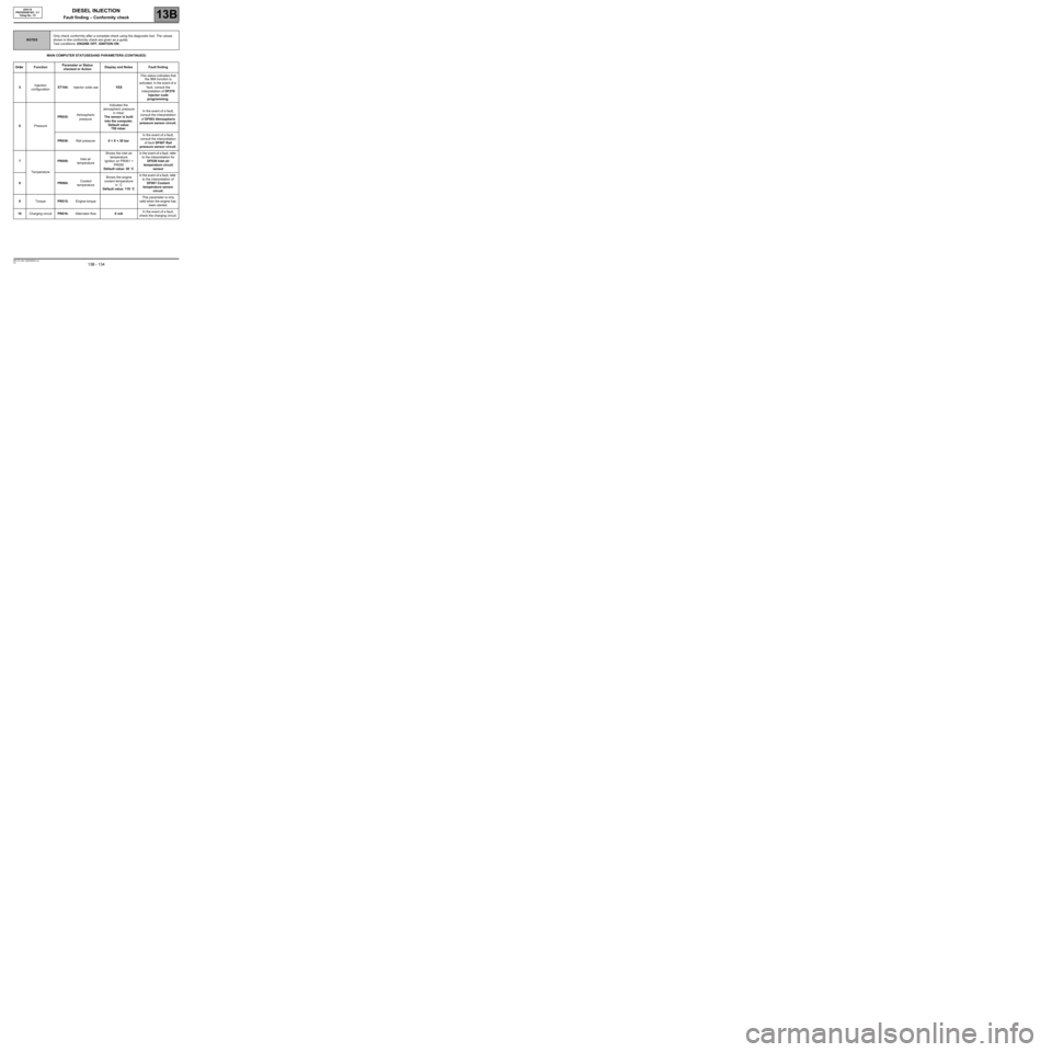
MAIN COMPUTER STATUSES AND PARAMETERS (CONTINUED)
NOTESOnly check conformity after a complete check using the diagnostic tool. The values
shown in this conformity check are given as a guide.
Test conditions: ENGINE OFF, IGNITION ON.
Order FunctionParameter or Status
checked or ActionDisplay and Notes Fault finding
5Injection
configurationET104:Injector code useYESThis status indicates that
the IMA function is
activated. In the event of a
fault, consult the
interpretation of DF276
Injector code
programming.
6PressurePR035:Atmospheric
pressureIndicates the
atmospheric pressure
in mbar.
The sensor is built
into the computer.
Default value:
750 mbar.In the event of a fault,
consult the interpretation
of DF003 Atmospheric
pressure sensor circuit.
PR038:Rail pressure0 < X < 30 barIn the event of a fault,
consult the interpretation
of fault DF007 Rail
pressure sensor circuit.
7
TemperaturePR059:Inlet air
temperatureShows the inlet air
temperature
Ignition on PR061 =
PR059
Default value: 20 ˚CIn the event of a fault, refer
to the interpretation for
DF039 Inlet air
temperature circuit
sensor
8PR064:Coolant
temperatureShows the engine
coolant temperature
in ˚C
Default value: 119 ˚CIn the event of a fault, refer
to the interpretation of
DF001 Coolant
temperature sensor
circuit.
9TorquePR015:Engine torqueThis parameter is only
valid when the engine has
been started.
10Charging circuitPR016:Alternator flow0 mAIn the event of a fault,
check the charging circuit.
Page 146 of 273
DIESEL INJECTION
Fault finding – Conformity check13B
13B - 146V3 MR-372-J84-13B250$450.mif
EDC16
PROGRAM NO.: C1
Vdiag No.: 51
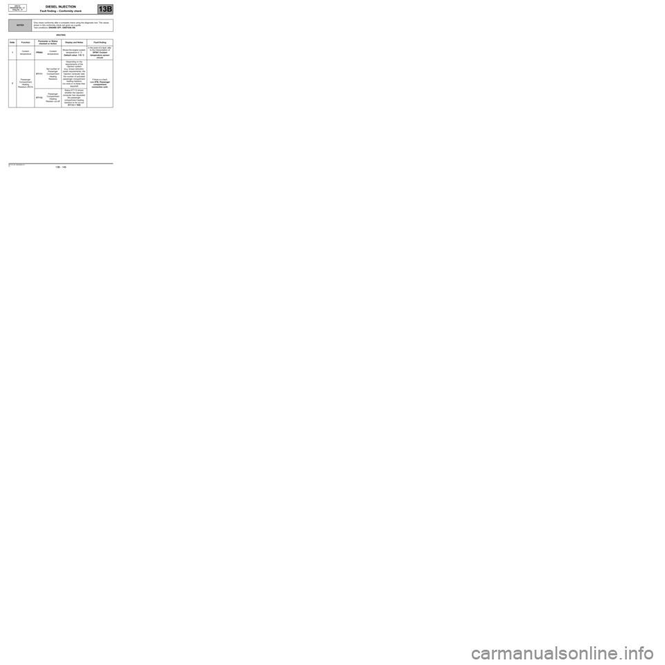
HEATING
NOTESOnly check conformity after a complete check using the diagnostic tool. The values
shown in this conformity check are given as a guide.
Test conditions: ENGINE OFF, IGNITION ON.
Order FunctionParameter or Status
checked or ActionDisplay and Notes Fault finding
1Coolant
temperaturePR064:Coolant
temperatureShows the engine coolant
temperature in ˚C
Default value: 119 ˚CIn the event of a fault, refer
to the interpretation of
DF001 Coolant
temperature sensor
circuit.
2Passenger
Compartment
Heating
Resistors (RCH)ET111:Set number of
Passenger
Compartment
Heating
ResistorsDepending on the
requirements of the
injection system
(e.g. torque reduction,
power requirements), the
injection computer sets
the number of activated
passenger compartment
heating resistors
(no more or no fewer than
required)If there is a fault,
(see 87B, Passenger
compartment
connection unit).
ET112:Passenger
Compartment
Heating
Resistor cut-offStatus ET112 shows
whether the injection
computer has requested
the passenger
compartment heating
resistors to be cut out
ET112 = YES
Page 153 of 273
DIESEL INJECTION
Fault finding – Conformity check13B
13B - 153V3 MR-372-J84-13B250$450.mif
EDC16
PROGRAM NO.: C1
Vdiag No.: 51
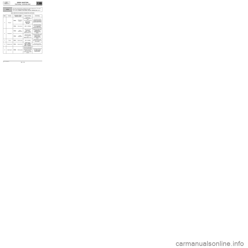
MAIN COMPUTER STATUSES AND PARAMETERS (CONTINUED)
NOTESOnly check conformity after a complete check using the diagnostic tool. The values
shown in this conformity check are given as a guide.
Test Conditions: ENGINE AT IDLE SPEED, COOLANT TEMPERATURE > 80 ˚C.
Order FunctionParameter or Status
checked or ActionDisplay and Notes Fault finding
5PressurePR035:Atmospheric
pressureIndicates the
atmospheric pressure in
mbar.
The sensor is built into
the computer.
Default value:
750 mbar.In the event of a fault,
consult the interpretation
of DF003 Atmospheric
pressure sensor circuit.
PR038:Rail pressure250 < X < 350 barIn the event of a fault,
consult the interpretation
of fault DF007 Rail
pressure sensor circuit.
6TemperaturePR059:Inlet air
temperatureShows the inlet air
temperature
PR061 = PR059
Default value: 20 ˚CIn the event of a fault, refer
to the interpretation for
DF039 Inlet air
temperature circuit
sensor
PR064:Coolant
temperatureShows the engine
coolant temperature
in ˚C
Default value: 119 ˚CIn the event of a fault, refer
to the interpretation of
DF001 Coolant
temperature sensor
circuit.
7TorquePR015:Engine torque20 < X < 40 NmThis parameter is only
valid when the engine has
been started.
8Charging circuitPR016:Alternator flowWarm engine
1500 < X < 2500 mA
With consumers:
2500 < X < 3600 mAIn the event of a fault,
check the charging circuit.
9Speed signalPR089:Vehicle speedGives the vehicle speed
in mph. This parameter is
transmitted by the ABS
computer. This signal is
transmitted to the
injection on the multiplex
network.In the event of a fault, test
the multiplex network.
See 38C Anti-lock
braking system.
Page 165 of 273
DIESEL INJECTION
Fault finding – Conformity check13B
13B - 165V3 MR-372-J84-13B250$540.mif
EDC16
PROGRAM NO.: C1
Vdiag No.: 51
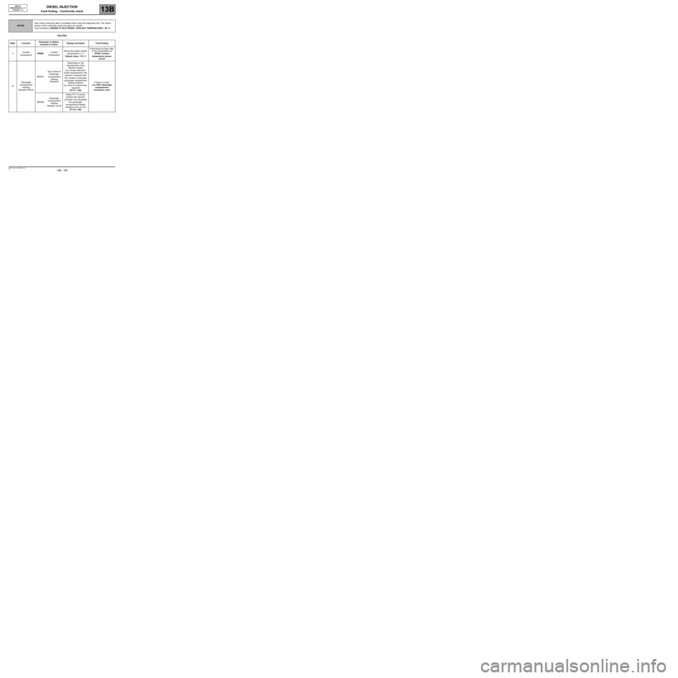
HEATING
NOTESOnly check conformity after a complete check using the diagnostic tool. The values
shown in this conformity check are given as a guide.
Test Conditions: ENGINE AT IDLE SPEED, COOLANT TEMPERATURE > 80 ˚C.
Order FunctionParameter or Status
checked or ActionDisplay and Notes Fault finding
1Coolant
temperaturePR064:Coolant
temperatureShows the engine coolant
temperature in ˚C
Default value: 119 ˚CIn the event of a fault, refer
to the interpretation of
DF001 Coolant
temperature sensor
circuit.
2Passenger
Compartment
Heating
Resistors (RCH)ET111:Set number of
Passenger
Compartment
Heating
ResistorsDepending on the
requirements of the
injection system
(e.g. torque reduction,
power requirements), the
injection computer sets
the number of activated
passenger compartment
heating resistors
(no more or no fewer than
required)
ET111 = NOIf there is a fault,
(see 87B, Passenger
compartment
connection unit).
ET112:Passenger
Compartment
Heating
Resistor cut-offStatus ET112 shows
whether the injection
computer has requested
the passenger
compartment heating
resistors to be cut out
ET112 = NO
Page 189 of 273
DIESEL INJECTION
Fault finding – Interpretation of statuses13B
13B - 189V3 MR-372-J84-13B250$630.mif
NO
EDC16
PROGRAM NO.: C1
Vdiag No.: 51
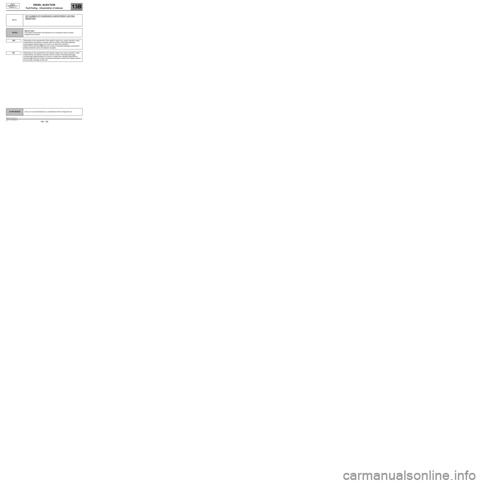
ET111
SET NUMBER OF PASSENGER COMPARTMENT HEATING
RESISTORS
NOTESSpecial notes:
Only perform these tests if the statuses do not correspond with the system
programming functions.
YES
Depending on the requirements of the injection system (e.g. torque reduction, power
requirements), the injection computer sets the number of activated passenger
compartment heating resistors (no more or no fewer than required)
Status ET111 becomes YES when the number of activated passenger compartment
heating resistors is set by the injection computer.
Depending on the requirements of the injection system (e.g. torque reduction, power
requirements), the injection computer sets the number of activated passenger
compartment heating resistors (no more or no fewer than required) Status ET111
becomes NO when the number of activated passenger compartment heating resistors
can be freely controlled by the UCH.
AFTER REPAIRCarry out a road test followed by a complete test with the diagnostic tool.
EDC16_V51_ET111
Page 190 of 273
DIESEL INJECTION
Fault finding – Interpretation of statuses13B
13B - 190V3 MR-372-J84-13B250$630.mif
NO
EDC16
PROGRAM NO.: C1
Vdiag No.: 51
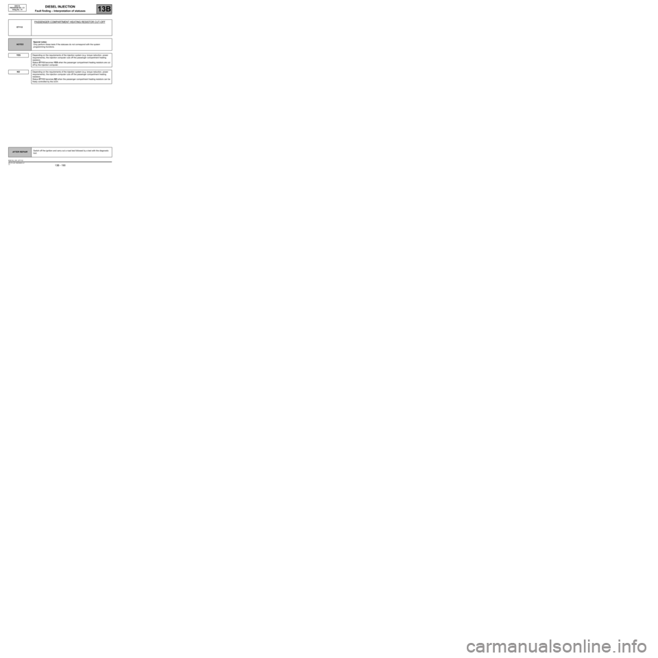
ET112
PASSENGER COMPARTMENT HEATING RESISTOR CUT-OFF
NOTESSpecial notes:
Only perform these tests if the statuses do not correspond with the system
programming functions.
YES
Depending on the requirements of the injection system (e.g. torque reduction, power
requirements), the injection computer cuts off the passenger compartment heating
resistors.
Status ET112 becomes YES when the passenger compartment heating resistors are cut
off by the injection computer.
Depending on the requirements of the injection system (e.g. torque reduction, power
requirements), the injection computer cuts off the passenger compartment heating
resistors.
Status ET112 becomes NO when the passenger compartment heating resistors can be
freely controlled by the UCH.
AFTER REPAIRSwitch off the ignition and carry out a road test followed by a test with the diagnostic
tool.
EDC16_V51_ET112