gearbox RENAULT SCENIC 2010 J95 / 3.G Engine And Pheripherals DCM 1.2 Injection User Guide
[x] Cancel search | Manufacturer: RENAULT, Model Year: 2010, Model line: SCENIC, Model: RENAULT SCENIC 2010 J95 / 3.GPages: 269
Page 157 of 269

13B-157
AFTER REPAIRDeal with any faults. Clear the faults from the computer memory.
Switch off the ignition and carry out a road test followed by a test with the diagnostic
tool.
V10 MR-372-J84-13B100$150.mif
DIESEL INJECTION
Fault finding – Interpretation of statuses13B
DCM 1.2 Injection
Program No.: 4D
Vdiag No.: 48, 4C, 50,
54, 58, 5C
ET415
CONTINUED 3
STATUS 6Gear lever in neutral (manual gearbox) or the neutral position (automatic gearbox)
Status ET415 becomes STATUS 6 when driving with cruise control active (ET042
Cruise control / speed limiter: CRUISE CONTROL) and:
–if the driver puts the gear lever in neutral position on a manual gearbox without
declutching or,
–if the gear lever is put in neutral on an automatic transmission.
This deactivates cruise control.
Reinitialise status ET415 on the injection computer by running command RZ001
"Fault memory".
If status ET415 becomes STATUS 6 without shifting the gear lever into neutral on a
manual gearbox without declutching, or into the neutral position on an automatic
transmission, run fault finding on the ABS computer and check the configuration of the
tyre size stored in the computer. If the configuration is correct, contact the Techline.
STATUS 7Lack of correlation between the request and the vehicle speed
Status ET415 becomes STATUS 7 if the computer detects too great a difference
between the speed requested by the driver and the vehicle speed.
This could occur when driving with cruise control active (ET042 Cruise control/ speed
limiter: CRUISE CONTROL) and when there is a significant difference.
This inconsistency deactivates cruise control.
Reinitialise status ET415 on the injection computer by running command RZ001
"Fault memory".
If status ET415 becomes STATUS 7 on flat terrain, contact the Techline.
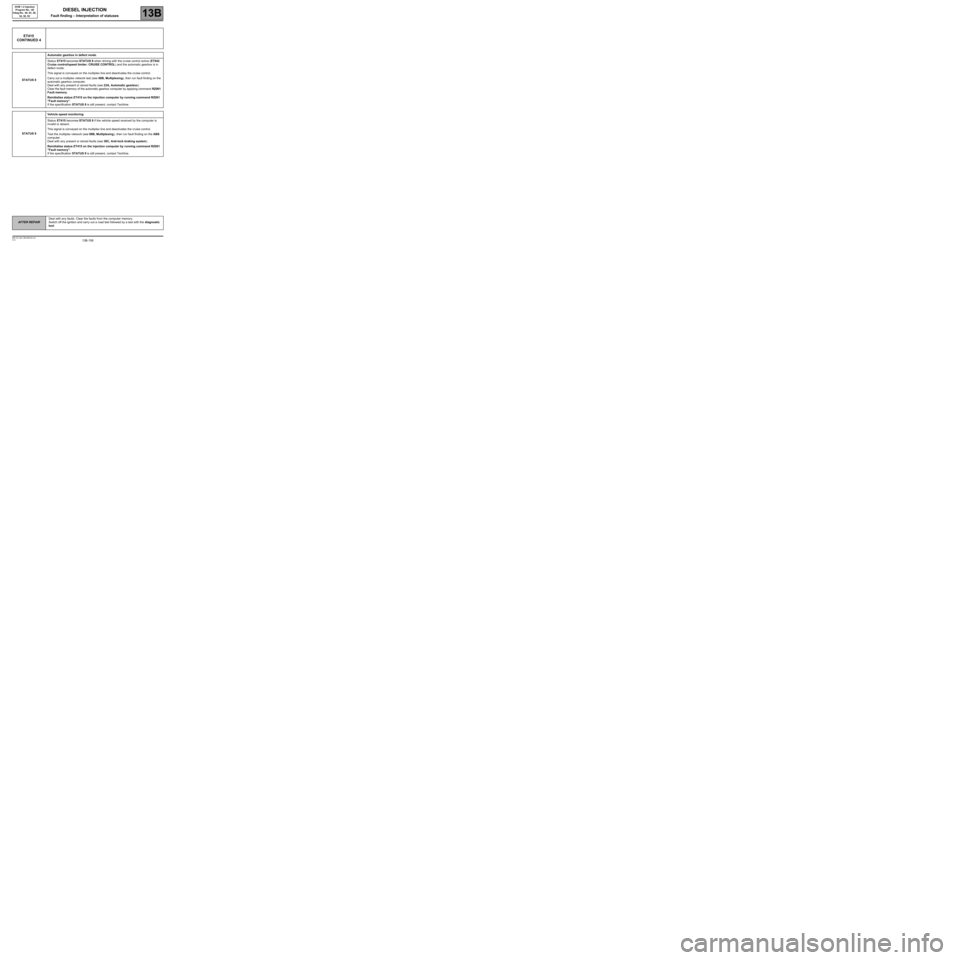
Page 158 of 269

13B-158
AFTER REPAIRDeal with any faults. Clear the faults from the computer memory.
Switch off the ignition and carry out a road test followed by a test with the diagnostic
tool.
V10 MR-372-J84-13B100$150.mif
DIESEL INJECTION
Fault finding – Interpretation of statuses13B
DCM 1.2 Injection
Program No.: 4D
Vdiag No.: 48, 4C, 50,
54, 58, 5C
ET415
CONTINUED 4
STATUS 8Automatic gearbox in defect mode.
Status ET415 becomes STATUS 8 when driving with the cruise control active (ET042
Cruise control/speed limiter: CRUISE CONTROL) and the automatic gearbox is in
defect mode.
This signal is conveyed on the multiplex line and deactivates the cruise control.
Carry out a multiplex network test (see 88B, Multiplexing), then run fault finding on the
automatic gearbox computer.
Deal with any present or stored faults (see 23A, Automatic gearbox).
Clear the fault memory of the automatic gearbox computer by applying command RZ001
Fault memory.
Reinitialise status ET415 on the injection computer by running command RZ001
"Fault memory".
If the specification STATUS 8 is still present, contact Techline.
STATUS 9Vehicle speed monitoring
Status ET415 becomes STATUS 9 if the vehicle speed received by the computer is
invalid or absent.
This signal is conveyed on the multiplex line and deactivates the cruise control.
Test the multiplex network (see 88B, Multiplexing), then run fault finding on the ABS
computer.
Deal with any present or stored faults (see 38C, Anti-lock braking system).
Reinitialise status ET415 on the injection computer by running command RZ001
"Fault memory".
If the specification STATUS 9 is still present, contact Techline.
Page 258 of 269

13B-258V10 MR-372-J84-13B100$210.mif
DIESEL INJECTION
Fault finding – Fault finding charts13B
DCM 1.2 Injection
Program No.: 4D
Vdiag No.: 48, 4C, 50,
54, 58, 5C
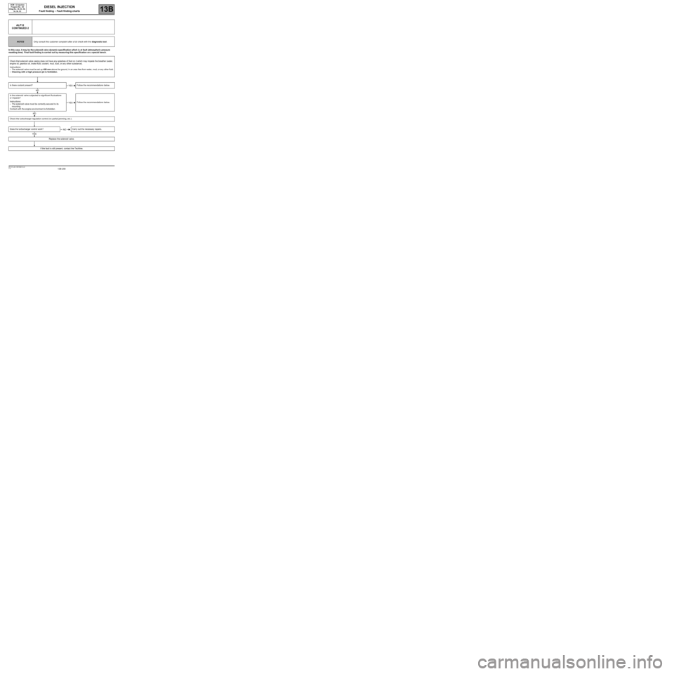
In this case, it may be the solenoid valve dynamic specification which is at fault (atmospheric pressure
resetting time). Final fault finding is carried out by measuring this specification on a special bench.
ALP12
CONTINUED 2
NOTESOnly consult this customer complaint after a full check with the diagnostic tool.
Check that solenoid valve casing does not have any splashes of fluid on it which may impede the breather (water,
engine oil, gearbox oil, brake fluid, coolant, mud, dust, or any other substance).
Instructions:
–The solenoid valve must be set up 450 mm above the ground, in an area free from water, mud, or any other fluid.
–Cleaning with a high pressure jet is forbidden.
Is there coolant present? Follow the recommendations below.
Is the solenoid valve subjected to significant fluctuations
or impacts?
Instructions:
–The solenoid valve must be correctly secured to its
mounting.
Contact with the engine environment is forbidden.Follow the recommendations below.
Check the turbocharger regulation control (no partial jamming, etc.).
Does the turbocharger control work? Carry out the necessary repairs.
Replace the solenoid valve.
If the fault is still present, contact the Techline.
YES
NO
YES
NO
NO
YES
Page 264 of 269

13B-264V10 MR-372-J84-13B100$210.mif
DIESEL INJECTION
Fault finding – Fault finding charts13B
DCM 1.2 Injection
Program No.: 4D
Vdiag No.: 48, 4C, 50,
54, 58, 5C
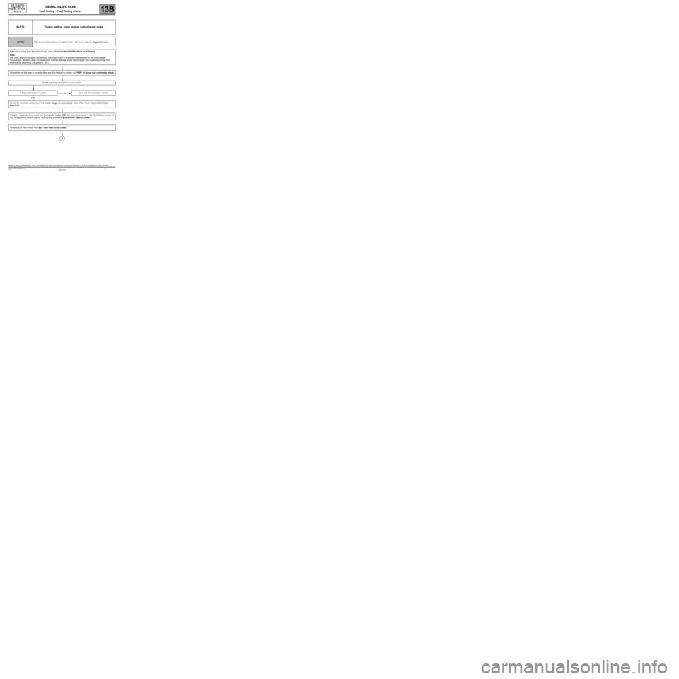
ALP16 Engine rattling, noisy engine, turbocharger noise
NOTESOnly consult this customer complaint after a full check with the diagnostic tool.
If the noise arises from the turbocharger, apply Technical Note 5164A, Noise fault finding.
Note:
Pay close attention to faulty components that might result in unjustified replacement of the turbocharger.
For example, whistling does not necessarily indicate damage to the turbocharger (this could be coming from
the exhaust, the timing, the gearbox, etc.).
Check that the fuel tank is correctly filled and that the fuel is correct: run TEST 13 Diesel fuel conformity check.
Check the levels of engine oil and coolant.
Is the compression in order? Carry out the necessary repairs.
Check the electrical conformity of the heater plugs (the resistance value of the heater plug must be less
than 2 ΩΩ Ω Ω
).
Using the diagnostic tool, check that the injector codes (C2I) are correctly entered on the identification screen. If
not, configure the correct injector codes using command SC002 Enter injector codes.
Check the air inlet circuit: run TEST 5 Air inlet circuit check.
NO
YES
A
DCM1.2_V48_ALP16/DCM1.2_V4C_ALP16/DCM1.2_V50_ALP16/DCM1.2_V54_ALP16/DCM1.2_V58_ALP16/DCM1.2_V5C_ALP16