ABS RENAULT SCENIC 2010 J95 / 3.G Engine And Pheripherals DCM 1.2 Injection Workshop Manual
[x] Cancel search | Manufacturer: RENAULT, Model Year: 2010, Model line: SCENIC, Model: RENAULT SCENIC 2010 J95 / 3.GPages: 269
Page 6 of 269
13B-6V10 MR-372-J84-13B100$010.mif
DIESEL INJECTION
Fault finding – Introduction13B
DCM 1.2 Injection
Program No.: 4D
Vdiag No.: 48, 4C, 50,
54, 58, 5C
4.2 Connector check
1. Visual inspection of the connection:
–Check that the connector is connected correctly and that the male and female parts of the connection are
correctly coupled.
2. Visual inspection of the area around the connection:
–Check the condition of the mounting (pin, strap, adhesive tape, etc.) if the connectors are attached to
the vehicle.
–Check that there is no damage to the wiring trim (sheath, foam, adhesive tape, etc.) near the wiring.
–Check that there is no damage to the electrical wires at the connector outputs, in particular on the insulating
material (wear, cuts, burns, etc.).
Disconnect the connector to continue the checks.
3. Visual inspection of the plastic casing:
–Check that there is no mechanical damage (casing crushed, split, broken, etc.), in particular to the fragile
components (lever, lock, sockets, etc.).
–Check that there is no heat damage (casing melted, darker, deformed, etc.).
–Check that there are no stains (grease, mud, liquid, etc.).
4. Visual inspection of the metal contacts:
(The female contact is called CLIP. The male contact is called TAB.)
–Check that there are no bent contacts (the contact is not inserted correctly and can come out of the back of
the connector). The spring contact of the connector when the wire is pulled slightly.
–Check that there is no damage (folded tabs, clips open too wide, blackened or melted contact, etc.).
–Check that there is no oxidation on the metal contacts.
5. Visual inspection of the sealing:
(Only for watertight connectors)
–Check for the seal on the connection (between the 2 parts of the connection).
–Check the seal at the back of the connectors:
–For unit seals (1 for each wire), check that the unit seals are present on each electrical wire and that they are
correctly positioned in the opening (level with the housing). Check that plugs are present on openings which
are not used.
–For a grommet seal (one seal which covers the entire internal surface of the connector), check that the seal is
present.
–For gel seals, check for gel in all of the sockets without removing the excess or any protruding sections (it does
not matter if there is gel on the contacts).
–For hotmelt sealing (heat-shrink sheath with glue), check that the sheath has contracted correctly on the rear
of the connectors and the electrical wires, and that the hardened glue comes out of the side of the wire.
–Check that there is no damage to any of the seals (cuts, burns, significant deformation, etc.).
If a fault is detected, consult Technical Note 6015A, Repairing electrical wiring. Note:
Carry out each requested check visually. Do not remove a connector if it is not required.
Note:
Repeated connections and disconnections alter the functionality of the connectors and increase the risk of poor
electrical contact. Limit the number of connections/disconnections as much as possible.
Note:
The check is carried out on the 2 parts of the connection. There may be 2 types of connections:
–Connector/Connector.
–Connector/Device.
Page 17 of 269
13B-17V10 MR-372-J84-13B100$040.mif
DIESEL INJECTION
Fault finding – Function13B
DCM 1.2 Injection
Program No.: 4D
Vdiag No.: 48, 4C, 50,
54, 58, 5C
Function: Hosted functions
Air conditioning management assistance
On models with air conditioning, the DCM1.2 system allows the air conditioning to be deactivated under certain
operating conditions:
–when requested by the driver,
–when starting the engine,
–if the engine overheats (in order to reduce the power the engine has to supply),
–when the engine speed is kept at a very high level (to protect the compressor),
–during transition phases (e.g. high acceleration demand for overtaking, anti-stalling and moving off). These
conditions are only taken into account if they do not occur repeatedly, so as to prevent system instabilities
(erratic deactivation),
–when certain faults appear.
Cold loop air conditioning management
The air conditioning is the cold loop type and its management shared between several computers. The injection
computer is responsible for:
–managing demand for cold air according to the passenger compartment commands and the pressure value,
–determining the power absorbed by the compressor from the pressure,
–determining the fan unit commands according to vehicle speed and pressure.
The driver requests the instrument panel to switch on the air conditioning. The signal is sent to the injection computer
via the multiplex line network. The cold air request is authorised or denied depending on the pressure measured. If
this pressure is outside the operating limits, the cold loop program is not activated.
Thermal regulation of the passenger compartment heating circuit
In a direct injection engine, fuel is injected directly into the combustion chamber. This leads to heat being lost
through the upper part of the engine and consequently, the cylinder head cooling system is smaller in size.
The effect of this is that the temperature of the coolant which flows through this circuit rises more slowly. This coolant
is also used by the passenger compartment heating system. In very cold conditions, it is therefore difficult to achieve
a comfortable passenger compartment temperature quickly.
To reduce the time taken to produce heat, air heating elements, called passenger compartment heating resistors,
are fitted in the passenger compartment heating circuit. The UCH decides whether or not to switch on the passenger
compartment heating resistors, and the UPC or the injection physically controls the heating elements. The injection
computer determines whether to reduce the power supplied to the passenger compartment heating resistors
according to the alternator load and also whether to inhibit the operation of the passenger compartment heating
resistors according to the engine speed, the load, and the vehicle speed.Note:
Fan unit actuation requests can be sent by the injection computer, but these are sent via the multiplex line. These
requests depend on the air conditioning, but also on the engine coolant temperature and vehicle speed.
Page 45 of 269
13B-45
AFTER REPAIRDeal with any faults displayed by the diagnostic tool.
Clear the computer fault memory.
Carry out a road test followed by another check with the diagnostic tool.
V10 MR-372-J84-13B100$090.mif
DIESEL INJECTION
Fault finding – Interpretation of faults13B
DCM 1.2 Injection
Program No.: 4D
Vdiag No.: 48, 4C, 50,
54, 58, 5C
* VSU: Vehicle Speed Unit
DF014
PRESENT
OR STOREDVEHICLE SPEED SIGNAL CIRCUIT
NOTESSpecial note:
None.
On this type of vehicle, the ABS or the VSU* (if the vehicle is not fitted with ABS) transmits the vehicle speed
information via the multiplex network.
Run the multiplex network test (see 88B, Multiplexing) to be able to work on the CAN network (Fault on CAN H
and CAN L lines between the injection and the ABS). Also check that there are no faults in the ABS computer
(see 38C, Anti-lock braking system) or in the system delivering the vehicle speed (VSU, see 38G, Vehicle speed
computer).
DCM1.2_V48_DF014/DCM1.2_V4C_DF014/DCM1.2_V50_DF014/DCM1.2_V54_DF014/DCM1.2_V58_DF014/DCM1.2_V5C_DF014
Page 74 of 269
13B-74
AFTER REPAIRDeal with any faults displayed by the diagnostic tool.
Clear the computer fault memory.
Carry out a road test followed by another check with the diagnostic tool.
V10 MR-372-J84-13B100$110.mif
13B
DCM 1.2 Injection
Program No.: 4D
Vdiag No.: 48, 4C, 50,
54, 58, 5C
DF039
PRESENT
OR
STOREDINLET AIR TEMPERATURE SENSOR CIRCUIT
CO.1: Open circuit or short circuit to +12 V
CC.0: Short circuit to earth
NOTESSpecial notes:
When this fault arises, the engine is noisy and a light smoke appears.
See the Technical Note Wiring Diagrams for the vehicle.
IMPORTANT
The Inlet air temperature sensor is absent when the engine is fitted with a flow sensor. In this case, its value is not
a true representation and is fixed on the following engines: K9K766, K9K724 in Vdiag 4C and 50.
It will always be absent on K9K 766, 768, 724 in Vdiag 48, as well as on K9K 768 Vdiag 4C and 50.
ENGINE: K9K 750
Move the wiring between the computer, component code 120 and the injection air temperature and pressure
sensor, component code 1474 to see if the status changes (present stored).
Look for any wiring damage and check the connection and condition of the inlet air temperature and pressure
sensor, component code 1474 and its connections.
If the connector is faulty and there is a repair procedure (see Technical Note 6015A, Repairing electrical wiring,
Wiring: Precautions for repair), repair the connector, otherwise replace the wiring.
If the resistance of the air temperature sensor is not:
15614 Ω ± 828 Ω at -20
°C
5887 Ω ± 283 Ω at 0
°C
2511 Ω ± 108 Ω at 20
°C
1200 Ω ± 47 Ω at 40
°C
612 Ω ± 22 Ω at 60
°C,
replace the air temperature sensor.
Check the insulation and continuity of the following connections:
–3KQ between components 1474 and 120,
–3LQ between components 1474 and 120,
–3LN between components 1474 and 120.
If the connection or connections are faulty and there is a repair procedure (see Technical Note 6015A, Electrical
wiring repair, Wiring: Precautions for repair), repair the wiring, otherwise replace the wiring.
If the fault is still present, replace the inlet air temperature and pressure sensor, component code 1474.
If the fault is still present, contact the Techline.
DCM1.2_V48_DF039/DCM1.2_V4C_DF039/DCM1.2_V50_DF039/DCM1.2_V54_DF039/DCM1.2_V58_DF039/DCM1.2_V5C_DF039
DIESEL INJECTION
Fault finding – Interpretation of faults
Page 84 of 269
13B-84
AFTER REPAIRDeal with any faults displayed by the diagnostic tool.
Clear the computer fault memory.
Carry out a road test followed by another check with the diagnostic tool.
V10 MR-372-J84-13B100$110.mif
DIESEL INJECTION
Fault finding – Interpretation of faults13B
DCM 1.2 Injection
Program No.: 4D
Vdiag No.: 48, 4C, 50,
54, 58, 5C
DF052
CONTINUED
DF052
PRESENTThe injectors are not defective.
Check the condition and connection of the injection computer (brown 48-track)
connector B.
If the connector is faulty and there is a repair procedure (see Technical Note 6015A,
Repairing electrical wiring, Wiring: Precautions for repair), repair the connector(s),
otherwise replace the wiring.
Check the insulation, the continuity and the absence of interference resistance on
the following connections:
–3L between components 193 and 120,
–3KW between components 193 and 120,
–3LA between components 194 and 120,
–3KX between components 194 and 120,
–3LB between components 195 and 120,
–3KY between components 195 and 120,
–3LC between components 196 and 120,
–3KZ between components 196 and 120.
If the connection or connections are faulty and there is a repair procedure
(see Technical Note 6015A, Electrical wiring repair, Wiring: Precautions for repair),
repair the wiring, otherwise replace the wiring.
If the fault is still present, contact the Techline.
DF052
STOREDInjector(s) defective.
Replace the injector identified by faults DF026 Cylinder 1 injector control circuit to
DF029 Cylinder 4 injector control circuit if any are present.
If none of the faults identifying the defective injector circuit are present:
–switch off the ignition,
–reconnect one of the four injectors,
–switch on the ignition again.
If the fault recurs as present, replace the reconnected injector, component code 193,
194, 195, or 196 (see MR 364 (Mégane II), MR 370 (Scénic II), MR 385 (Modus), MR
392 (Clio III), MR 411 (New Twingo), MR 417 (Kangoo 2), Mechanical, 13B,
Diesel injection, Diesel injector: Removal - Refitting).
Follow the same procedure for the other injectors.
Page 94 of 269
13B-94
AFTER REPAIRDeal with any faults displayed by the diagnostic tool.
Clear the computer fault memory.
Carry out a road test followed by another check with the diagnostic tool.
V10 MR-372-J84-13B100$110.mif
DIESEL INJECTION
Fault finding – Interpretation of faults13B
DCM 1.2 Injection
Program No.: 4D
Vdiag No.: 48, 4C, 50,
54, 58, 5C
DF089
PRESENT
OR
STOREDINLET MANIFOLD PRESSURE SENSOR CIRCUIT1.DEF: Permanent low level
2.DEF: Permanent high level
3.DEF: Below minimum threshold
4.DEF: Above maximum threshold
5.DEF: Inconsistency
6.DEF: At maximum stop
7.DEF: At minimum stop
NOTESPriority in dealing with a number of faults:
–DF113 Sensor supply voltage.
Special notes:
The level 1 warning light illuminates accompanied by the message Check
injection.
See Technical Note Wiring Diagrams of the vehicle concerned.
1.DEF
2.DEF
3.DEF
4.DEF
NOTESNone.
Check the connection and condition of the inlet pressure sensor connector, component code 1071.
Check the connection and condition of connector B (brown 48-track) of the injection computer, component
code 120.
If the connector(s) is faulty and if there is a repair procedure (see Technical Note 6015A, Repairing electrical
wiring, Wiring: Precautions for repair), repair the connector, otherwise replace the wiring.
Check for + 5 V on connection 3LQ of component 1071 (or 1474 for the K9K750).
Check for earth on connection 3LN of component 1071 (or 1474 for the K9K750).
Check the insulation, the continuity and the absence of interference resistance on the following connections:
–3LQ between components 120 and 1071 (or 1474 for the K9K750).
–3LP between components 120 and 1071 (or 1474 for the K9K750).
–3LN between components 120 and 1071 (or 1474 for the K9K750).
If the connection or connections are faulty and there is a repair procedure (see Technical Note 6015A, Electrical
wiring repair, Wiring: Precautions for repair), repair the wiring, otherwise replace the wiring.
If the fault is still present, contact the Techline.
DCM1.2_V48_DF089/DCM1.2_V4C_DF089/DCM1.2_V50_DF089/DCM1.2_V54_DF089/DCM1.2_V58_DF089/DCM1.2_V5C_DF089
Page 96 of 269
13B-96
AFTER REPAIRDeal with any faults displayed by the diagnostic tool.
Clear the computer fault memory.
Carry out a road test followed by another check with the diagnostic tool.
V10 MR-372-J84-13B100$110.mif
DIESEL INJECTION
Fault finding – Interpretation of faults13B
DCM 1.2 Injection
Program No.: 4D
Vdiag No.: 48, 4C, 50,
54, 58, 5C
DF098
PRESENT
OR
STOREDFUEL TEMPERATURE SENSOR CIRCUIT
CO.1: Open circuit or short circuit to + 12 V
CC.0: Short circuit to earth
NOTESNone.
See Technical Note Wiring Diagrams of the vehicle concerned.
Check the connection and condition of the fuel temperature sensor connector, component code 1066.
Check the connection and condition of connector B (brown 48-track) of the injection computer, component
code 120.
If the connector(s) is faulty and if there is a repair procedure (see Technical Note 6015A, Repairing electrical
wiring, Wiring: Precautions for repair), repair the connector, otherwise replace the wiring.
Check the insulation, the continuity and the absence of interference resistance on the following connections:
–3FAB between components 1066 and 120,
–3LD between components 1066 and 120.
If the connection or connections are faulty and there is a repair procedure (see Technical Note 6015A, Electrical
wiring repair, Wiring: Precautions for repair), repair the wiring, otherwise replace the wiring.
Measure the resistance at the fuel temperature sensor terminals.
If the resistance of the fuel temperature sensor is not approximately 2.2 kΩ at 25
°C, replace the fuel temperature
sensor, component code 1066 (see MR 364 (Mégane II), MR 370 (Scénic II), MR 385 (Modus), MR 392 (Clio III),
MR 411 (Nouvelle Twingo), MR 417 (Kangoo 2), Mechanical, 13B, Diesel injection, Fuel temperature sensor,
Removal - Refitting).
DCM1.2_V48_DF098/DCM1.2_V4C_DF098/DCM1.2_V50_DF098/DCM1.2_V54_DF098/DCM1.2_V58_DF098/DCM1.2_V5C_DF098
Page 97 of 269
13B-97
AFTER REPAIRDeal with any faults displayed by the diagnostic tool.
Clear the computer fault memory.
Carry out a road test followed by another check with the diagnostic tool.
V10 MR-372-J84-13B100$110.mif
DIESEL INJECTION
Fault finding – Interpretation of faults13B
DCM 1.2 Injection
Program No.: 4D
Vdiag No.: 48, 4C, 50
DF099
PRESENT
OR
STOREDAUTOMATIC TRANSMISSION OR SEQUENTIAL GEARBOX
CONNECTION VIA THE MULTIPLEX NETWORK
1.DEF: No signal
NOTESSpecial notes:
–Gearbox does not change gear in automatic mode.
–OBD warning light illuminated.
See Technical Note Wiring Diagrams of the vehicle concerned.
Run a multiplex network test (see 88B, Multiplex).
Check the connection and condition of connector A (black 52-track) of the sequential gearbox computer,
component code 119.
Check the connection and condition of connector C (brown 48-track) of the injection computer, component
code 120.
If the connector(s) is faulty and if there is a repair procedure (see Technical Note 6015A, Repairing electrical
wiring, Wiring: Precautions for repair), repair the connector, otherwise replace the wiring.
Check the insulation, the continuity and the absence of interference resistance on the following connections:
–3MT between components 119 and 120,
–3MS between components 119 and 120.
If the connection or connections are faulty and there is a repair procedure (see Technical Note 6015A, Electrical
wiring repair, Wiring: Precautions for repair), repair the wiring, otherwise replace the wiring.
DCM1.2_V48_DF099/DCM1.2_V4C_DF099/DCM1.2_V50_DF099
Page 99 of 269
13B-99
AFTER REPAIRDeal with any faults displayed by the diagnostic tool.
Clear the computer fault memory.
Carry out a road test followed by another check with the diagnostic tool.
V10 MR-372-J84-13B100$110.mif
DIESEL INJECTION
Fault finding – Interpretation of faults13B
DCM 1.2 Injection
Program No.: 4D
Vdiag No.: 48, 4C, 50,
54, 58, 5C
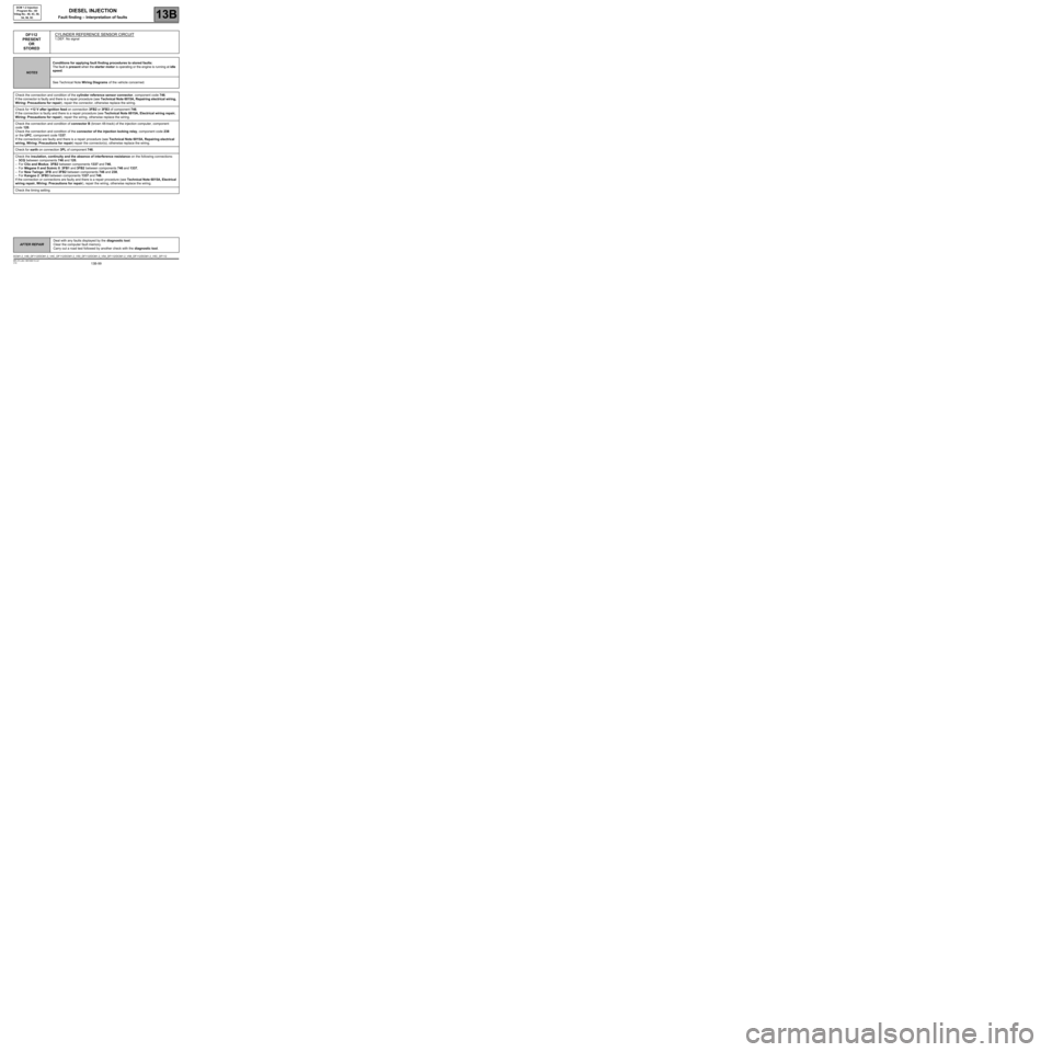
DF112
PRESENT
OR
STOREDCYLINDER REFERENCE SENSOR CIRCUIT
1.DEF: No signal
NOTESConditions for applying fault finding procedures to stored faults:
The fault is present when the starter motor is operating or the engine is running at idle
speed.
See Technical Note Wiring Diagrams of the vehicle concerned.
Check the connection and condition of the cylinder reference sensor connector, component code 746.
If the connector is faulty and there is a repair procedure (see Technical Note 6015A, Repairing electrical wiring,
Wiring: Precautions for repair), repair the connector, otherwise replace the wiring.
Check for +12 V after ignition feed on connection 3FB2 or 3FB3 of component 746.
If the connection is faulty and there is a repair procedure (see Technical Note 6015A, Electrical wiring repair,
Wiring: Precautions for repair), repair the wiring, otherwise replace the wiring.
Check the connection and condition of connector B (brown 48-track) of the injection computer, component
code 120.
Check the connection and condition of the connector of the injection locking relay, component code 238
or the UPC, component code 1337.
If the connector(s) are faulty and there is a repair procedure (see Technical Note 6015A, Repairing electrical
wiring, Wiring: Precautions for repair) repair the connector(s), otherwise replace the wiring.
Check for earth on connection 3PL of component 746.
Check the insulation, continuity and the absence of interference resistance on the following connections:
–3CQ between components 746 and 120,
–For Clio and Modus: 3FB2 between components 1337 and 746,
–For Mégane II and Scénic II: 3FB1 and 3FB2 between components 746 and 1337,
–For New Twingo: 3FB and 3FB2 between components 746 and 238,
–For Kangoo 2: 3FB3 between components 1337 and 746.
If the connection or connections are faulty and there is a repair procedure (see Technical Note 6015A, Electrical
wiring repair, Wiring: Precautions for repair), repair the wiring, otherwise replace the wiring.
Check the timing setting.
DCM1.2_V48_DF112/DCM1.2_V4C_DF112/DCM1.2_V50_DF112/DCM1.2_V54_DF112/DCM1.2_V58_DF112/DCM1.2_V5C_DF112
Page 101 of 269
13B-101
AFTER REPAIRDeal with any faults displayed by the diagnostic tool.
Clear the computer fault memory.
Carry out a road test followed by another check with the diagnostic tool.
V10 MR-372-J84-13B100$110.mif
DIESEL INJECTION
Fault finding – Interpretation of faults13B
DCM 1.2 Injection
Program No.: 4D
Vdiag No.: 48, 4C, 50,
54, 58, 5C
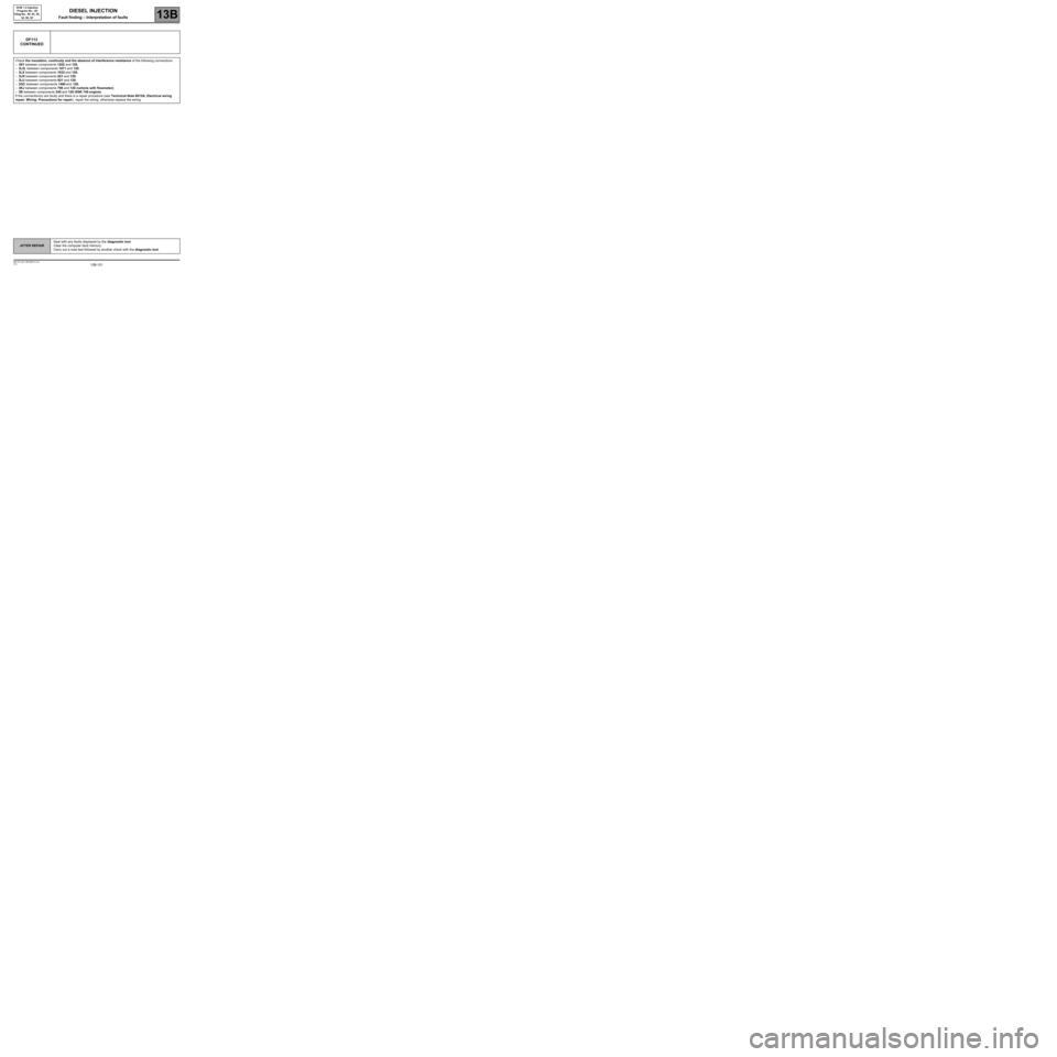
DF113
CONTINUED
Check the insulation, continuity and the absence of interference resistance of the following connections:
–38Y between components 1202 and 120,
–3LQ, between components 1071 and 120,
–3LX between components 1032 and 120,
–3LR between components 921 and 120,
–3LU between components 921 and 120,
–3GC between components 1460 and 120,
–3KJ between components 799 and 120 (vehicle with flowmeter),
–3B between components 245 and 120 (K9K 740 engine).
If the connection(s) are faulty and there is a repair procedure (see Technical Note 6015A, Electrical wiring
repair, Wiring: Precautions for repair), repair the wiring, otherwise replace the wiring.