ABS RENAULT SCENIC 2010 J95 / 3.G Engine And Pheripherals DCM 1.2 Injection Owner's Manual
[x] Cancel search | Manufacturer: RENAULT, Model Year: 2010, Model line: SCENIC, Model: RENAULT SCENIC 2010 J95 / 3.GPages: 269
Page 154 of 269
13B-154
AFTER REPAIRDeal with any faults. Clear the faults from the computer memory.
Switch off the ignition and carry out a road test followed by a test with the diagnostic
tool.
V10 MR-372-J84-13B100$150.mif
DIESEL INJECTION
Fault finding – Interpretation of statuses13B
DCM 1.2 Injection
Program No.: 4D
Vdiag No.: 48, 4C, 50,
54, 58, 5C
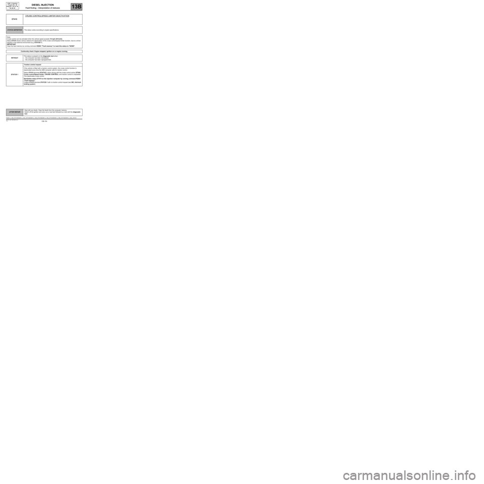
ET415CRUISE CONTROL/SPEED LIMITER DEACTIVATION
STATUS DEFINITIONThis status varies according to engine specifications.
Note:
Cruise control can be activated when the vehicle speed exceeds 18 mph (30 km/h).
Status ET415 shows various reasons for deactivation of the cruise control/speed limiter function, due to a driver
request or the external environment (e.g. STATUS 1).
IMPORTANT
Clear the fault memory by running command RZ001 "Fault memory" to reset this status to "NONE".
Conformity check: Engine stopped, ignition on or engine running.
WITHOUTThis status is present on the diagnostic tool when:
–the computer has been reinitialised.
–the computer has been reprogrammed.
STATUS 1Traction control request
If the vehicle is fitted with a traction control system, the cruise control function is
deactivated every time the ABS computer calls for traction control.
Status ET415 becomes STATUS 1 when driving with the cruise control active (ET042
Cruise control/Speed limiter: CRUISE CONTROL) and traction control is requested.
This deactivates cruise control.
Reinitialise status ET415 on the injection computer by running command RZ001
"Fault memory".
If status ET415 becomes STATUS 1 with no traction control request (see 38C, Anti-lock
braking system).
DCM1.2_V48_ET415/DCM1.2_V4C_ET415/DCM1.2_V50_ET415/DCM1.2_V54_ET415/DCM1.2_V58_ET415/DCM1.2_V5C_ET415
Page 157 of 269

13B-157
AFTER REPAIRDeal with any faults. Clear the faults from the computer memory.
Switch off the ignition and carry out a road test followed by a test with the diagnostic
tool.
V10 MR-372-J84-13B100$150.mif
DIESEL INJECTION
Fault finding – Interpretation of statuses13B
DCM 1.2 Injection
Program No.: 4D
Vdiag No.: 48, 4C, 50,
54, 58, 5C
ET415
CONTINUED 3
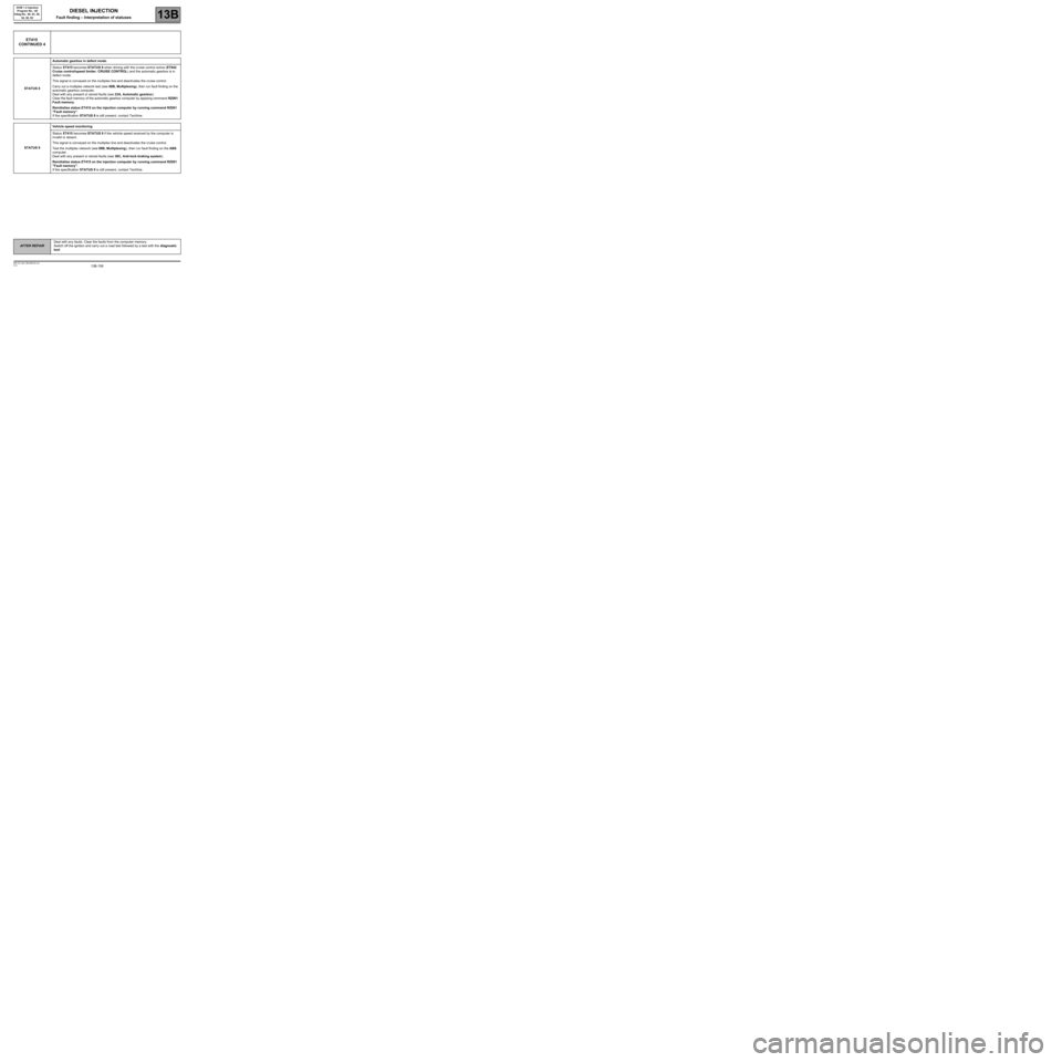
STATUS 6Gear lever in neutral (manual gearbox) or the neutral position (automatic gearbox)
Status ET415 becomes STATUS 6 when driving with cruise control active (ET042
Cruise control / speed limiter: CRUISE CONTROL) and:
–if the driver puts the gear lever in neutral position on a manual gearbox without
declutching or,
–if the gear lever is put in neutral on an automatic transmission.
This deactivates cruise control.
Reinitialise status ET415 on the injection computer by running command RZ001
"Fault memory".
If status ET415 becomes STATUS 6 without shifting the gear lever into neutral on a
manual gearbox without declutching, or into the neutral position on an automatic
transmission, run fault finding on the ABS computer and check the configuration of the
tyre size stored in the computer. If the configuration is correct, contact the Techline.
STATUS 7Lack of correlation between the request and the vehicle speed
Status ET415 becomes STATUS 7 if the computer detects too great a difference
between the speed requested by the driver and the vehicle speed.
This could occur when driving with cruise control active (ET042 Cruise control/ speed
limiter: CRUISE CONTROL) and when there is a significant difference.
This inconsistency deactivates cruise control.
Reinitialise status ET415 on the injection computer by running command RZ001
"Fault memory".
If status ET415 becomes STATUS 7 on flat terrain, contact the Techline.
Page 158 of 269
13B-158
AFTER REPAIRDeal with any faults. Clear the faults from the computer memory.
Switch off the ignition and carry out a road test followed by a test with the diagnostic
tool.
V10 MR-372-J84-13B100$150.mif
DIESEL INJECTION
Fault finding – Interpretation of statuses13B
DCM 1.2 Injection
Program No.: 4D
Vdiag No.: 48, 4C, 50,
54, 58, 5C
ET415
CONTINUED 4
STATUS 8Automatic gearbox in defect mode.
Status ET415 becomes STATUS 8 when driving with the cruise control active (ET042
Cruise control/speed limiter: CRUISE CONTROL) and the automatic gearbox is in
defect mode.
This signal is conveyed on the multiplex line and deactivates the cruise control.
Carry out a multiplex network test (see 88B, Multiplexing), then run fault finding on the
automatic gearbox computer.
Deal with any present or stored faults (see 23A, Automatic gearbox).
Clear the fault memory of the automatic gearbox computer by applying command RZ001
Fault memory.
Reinitialise status ET415 on the injection computer by running command RZ001
"Fault memory".
If the specification STATUS 8 is still present, contact Techline.
STATUS 9Vehicle speed monitoring
Status ET415 becomes STATUS 9 if the vehicle speed received by the computer is
invalid or absent.
This signal is conveyed on the multiplex line and deactivates the cruise control.
Test the multiplex network (see 88B, Multiplexing), then run fault finding on the ABS
computer.
Deal with any present or stored faults (see 38C, Anti-lock braking system).
Reinitialise status ET415 on the injection computer by running command RZ001
"Fault memory".
If the specification STATUS 9 is still present, contact Techline.
Page 165 of 269
13B-165
AFTER REPAIRDeal with any faults. Clear the faults from the computer memory.
Switch off the ignition and carry out a road test followed by a test with the diagnostic
tool.
V10 MR-372-J84-13B100$150.mif
DIESEL INJECTION
Fault finding – Interpretation of statuses13B
DCM 1.2 Injection
Program No.: 4D
Vdiag No.: 48, 4C, 50,
54, 58, 5C
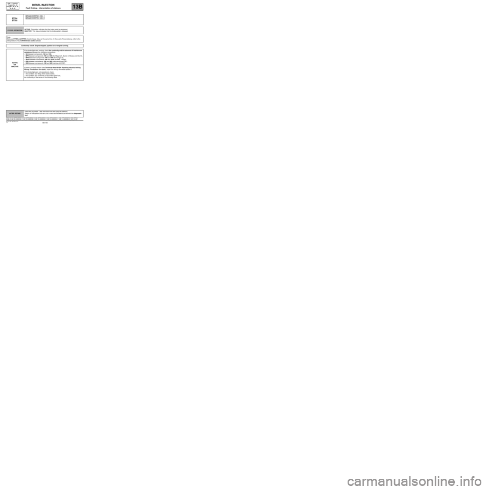
ET704
ET705BRAKE SWITCH NO. 1BRAKE SWITCH NO. 2
STATUS DEFINITIONACTIVE: This status indicates that the brake pedal is depressed.
INACTIVE: This status indicates that the brake pedal is released.
Note:
Statuses ET704 and ET705 should change status at the same time. In the event of inconsistency, refer to the
interpretation of fault DF050 Brake switch circuit.
Conformity check: Engine stopped, ignition on or engine running.
ACTIVE
OR
INACTIVEIf the brake lights are working, check the continuity and the absence of interference
resistance between the following connections:
–5A between components 160 and 120,
–BPT between components 160 and 645 (for Mégane II, Scénic II, Modus and Clio III),
–BPT2 between components 160 and 645 (for Kangoo 2),
–AP10 between components 160 and 1016 (for New Twingo),
–65A between components 160 and 645 (vehicle without ESP),
–65G between components 160 and 645 (vehicle with ESP).
If there is a repair method (see Technical Note 6015A, Repairing electrical wiring,
Wiring: Precautions for repair), repair the wiring, otherwise replace it.
If the brake lights are not operational, check:
–the condition and fitting of the brake switch,
–the condition and conformity of the brake lights fuse,
the conformity of the values in the following table:
DCM1.2_V48_ET704/DCM1.2_V4C_ET704/DCM1.2_V50_ET704/DCM1.2_V54_ET704/DCM1.2_V58_ET704/DCM1.2_V5C_ET704/
DCM1.2_V48_ET705/DCM1.2_V4C_ET705/DCM1.2_V50_ET705/DCM1.2_V54_ET705/DCM1.2_V58_ET705/DCM1.2_V5C_ET705
Page 175 of 269
13B-175
AFTER REPAIRDeal with any faults displayed by the diagnostic tool. Clear the computer fault
memory.
Carry out a road test followed by another check with the diagnostic tool.
V10 MR-372-J84-13B100$170.mif
DIESEL INJECTION
Fault finding – Interpretation of parameters13B
DCM 1.2 Injection
Program No.: 4D
Vdiag No.: 48, 4C, 50,
54, 58, 5C
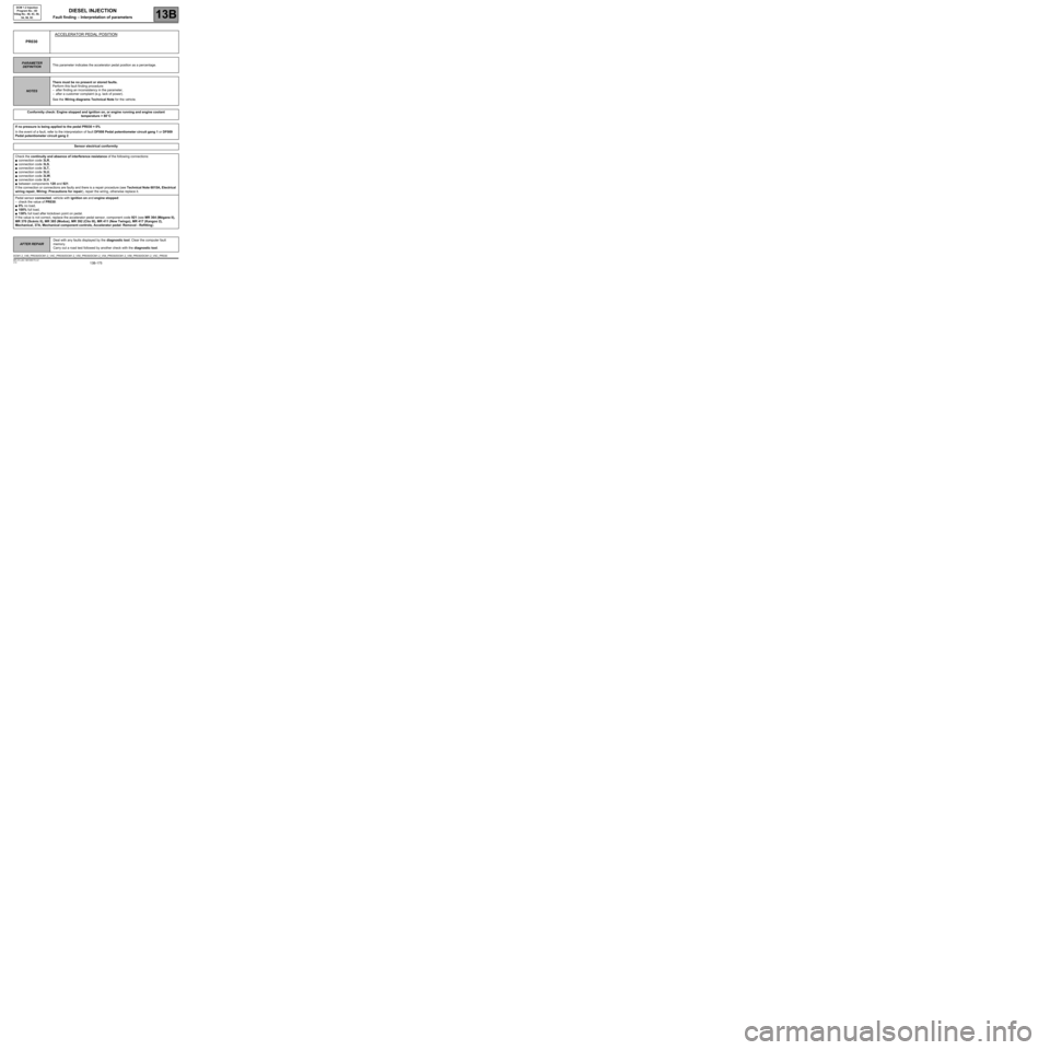
PR030ACCELERATOR PEDAL POSITION
PARAMETER
DEFINITIONThis parameter indicates the accelerator pedal position as a percentage.
NOTESThere must be no present or stored faults.
Perform this fault finding procedure:
–after finding an inconsistency in the parameter,
–after a customer complaint (e.g. lack of power).
See the Wiring diagrams Technical Note for the vehicle.
Conformity check: Engine stopped and ignition on, or engine running and engine coolant
temperature > 80
°C
If no pressure is being applied to the pedal PR030 = 0%
In the event of a fault, refer to the interpretation of fault DF008 Pedal potentiometer circuit gang 1 or DF009
Pedal potentiometer circuit gang 2.
Sensor electrical conformity
Check the continuity and absence of interference resistance of the following connections:
●connection code 3LR,
●connection code 3LS,
●connection code 3LT,
●connection code 3LU,
●connection code 3LW,
●connection code 3LV,
●between components 120 and 921.
If the connection or connections are faulty and there is a repair procedure (see Technical Note 6015A, Electrical
wiring repair, Wiring: Precautions for repair), repair the wiring, otherwise replace it.
Pedal sensor connected, vehicle with ignition on and engine stopped:
–check the value of PR030:
●0% no load,
●100% full load,
●138% full load after kickdown point on pedal.
If the value is not correct, replace the accelerator pedal sensor, component code 921 (see MR 364 (Mégane II),
MR 370 (Scénic II), MR 385 (Modus), MR 392 (Clio III), MR 411 (New Twingo), MR 417 (Kangoo 2),
Mechanical, 37A, Mechanical component controls, Accelerator pedal: Removal - Refitting).
DCM1.2_V48_PR030/DCM1.2_V4C_PR030/DCM1.2_V50_PR030/DCM1.2_V54_PR030/DCM1.2_V58_PR030/DCM1.2_V5C_PR030
Page 180 of 269
13B-180
AFTER REPAIRDeal with any faults displayed by the diagnostic tool. Clear the computer fault
memory.
Carry out a road test followed by another check with the diagnostic tool.
V10 MR-372-J84-13B100$170.mif
DIESEL INJECTION
Fault finding – Interpretation of parameters13B
DCM 1.2 Injection
Program No.: 4D
Vdiag No.: 48, 4C, 50,
54, 58, 5C
PR051EGR VALVE POSITION FEEDBACK
PARAMETER
DEFINITIONThis parameter indicates the EGR valve opening ratio.
NOTESThere must be no present or stored faults.
Perform this fault finding procedure:
–after finding an inconsistency in the parameter,
–after a customer complaint (loss of power, smoke etc.).
Special note:
Default value: 0%.
See the Wiring diagrams Technical Note for the vehicle.
Conformity check: Engine stopped and ignition on, or engine running and engine coolant
temperature > 80
°C
This parameter indicates the EGR valve opening ratio.
In the event of a fault, consult the interpretation of fault DF209 EGR valve position sensor circuit.
Sensor electrical conformity
Check for continuity and absence of interference resistance of the following connections:
●connection code 3JM,
●connection code 3EL,
●connection code 3GC,
●between components 120 and 1460.
If the connection or connections are faulty and there is a repair procedure (see Technical Note 6015A, Electrical
wiring repair, Wiring: Precautions for repair), repair the wiring, otherwise replace it.
If the fault is still present, contact the Techline.
DCM1.2_V48_PR051/DCM1.2_V4C_PR051/DCM1.2_V50_PR051/DCM1.2_V54_PR051/DCM1.2_V58_PR051/DCM1.2_V5C_PR051
Page 183 of 269
13B-183
AFTER REPAIRDeal with any faults displayed by the diagnostic tool. Clear the computer fault
memory.
Carry out a road test followed by another check with the diagnostic tool.
V10 MR-372-J84-13B100$170.mif
DIESEL INJECTION
Fault finding – Interpretation of parameters13B
DCM 1.2 Injection
Program No.: 4D
Vdiag No.: 48, 4C, 50,
54, 58, 5C
PR063FUEL TEMPERATURE
PARAMETER
DEFINITIONThis parameter indicates the fuel temperature in °C.
NOTESSpecial notes:
Default value: 40
°C.
There must be no present or stored faults.
Perform this fault finding procedure:
–after finding an inconsistency in the parameter,
–after a customer complaint (e.g. lack of power).
See the Wiring diagrams Technical Note for the vehicle.
Conformity check: Engine stopped and the ignition on, or the engine running and the engine coolant
temperature > 80
°C
- 30
°C < PR063 < 90°C.
In the event of a fault, consult the interpretation of fault DF098 Fuel temperature sensor circuit.
Sensor electrical conformity
Check the continuity and absence of interference resistance of the following connections:
–Connection code 3FAB,
–Connection code 3LD,
–between components 120 and 1066.
If the connection or connections are faulty and there is a repair procedure (see Technical Note 6015A, Electrical
wiring repair, Wiring: Precautions for repair), repair the wiring, otherwise replace it.
Measure the resistance between connections 3FAB and 3LD of component 1066.
If its resistance is not:
3538 Ω < R < 4102 Ω at + 10
°C
1950 Ω < R < 2150 Ω at + 25
°C
763 Ω < R < 857 Ω at + 50
°C,
replace the fuel temperature sensor, component code 1066 (see MR 364 (Mégane II), MR 370 (Scénic II), MR
385 (Modus), MR 392 (Clio III), MR 411 (New Twingo), MR 417 (Kangoo 2), Mechanical, 13B, Diesel Injection,
Fuel temperature sensor: Removal - Refitting).
DCM1.2_V48_PR063/DCM1.2_V4C_PR063/DCM1.2_V50_PR063/DCM1.2_V54_PR063/DCM1.2_V58_PR063/DCM1.2_V5C_PR063
Page 189 of 269
13B-189
AFTER REPAIRDeal with any faults displayed by the diagnostic tool. Clear the computer fault
memory.
Carry out a road test followed by another check with the diagnostic tool.
V10 MR-372-J84-13B100$170.mif
DIESEL INJECTION
Fault finding – Interpretation of parameters13B
DCM 1.2 Injection
Program No.: 4D
Vdiag No.: 48, 4C, 50,
54, 58, 5C
PR089VEHICLE SPEED
PARAMETER
DEFINITIONThis parameter indicates the vehicle speed in mph (km/h).
NOTESSpecial notes:
This parameter is transmitted by the ABS computer or by the wheel speed computer.
This signal is transmitted to the injection on the multiplex network.
Conformity check: Engine stopped and ignition on, or engine running and engine coolant
temperature > 80
°C
In the event of a fault, carry out a multiplex network test (see 88B, Multiplexing)
Then a complete fault finding procedure of the ABS computer (see 38C, Antilock braking system) or VSU
(see 38G, Wheel speed computer).
DCM1.2_V48_PR089/DCM1.2_V4C_PR089/DCM1.2_V50_PR089/DCM1.2_V54_PR089/DCM1.2_V58_PR089/DCM1.2_V5C_PR089
Page 190 of 269

13B-190
AFTER REPAIRDeal with any faults displayed by the diagnostic tool. Clear the computer fault
memory.
Carry out a road test followed by another check with the diagnostic tool.
V10 MR-372-J84-13B100$170.mif
DIESEL INJECTION
Fault finding – Interpretation of parameters13B
DCM 1.2 Injection
Program No.: 4D
Vdiag No.: 48, 4C, 50,
54, 58, 5C
PR125POWER ABSORBED BY THE AIR CONDITIONING COMPRESSOR*
PARAMETER
DEFINITIONThis parameter indicates the power absorbed by the air conditioning compressor in W.
Conformity check: Engine stopped and ignition on, or engine running without electrical consumer,
and engine coolant temperature > 80
°C
PR125 = 0 W
Conformity check: With engine running and compressor activation request active
PR125 = 1200 W
DCM1.2_V48_PR125/DCM1.2_V4C_PR125/DCM1.2_V50_PR125/DCM1.2_V54_PR125/DCM1.2_V58_PR125/DCM1.2_V5C_PR125
Page 193 of 269
13B-193
AFTER REPAIRDeal with any faults displayed by the diagnostic tool. Clear the computer fault
memory.
Carry out a road test followed by another check with the diagnostic tool.
V10 MR-372-J84-13B100$170.mif
DIESEL INJECTION
Fault finding – Interpretation of parameters13B
DCM 1.2 Injection
Program No.: 4D
Vdiag No.: 48, 4C, 50,
54, 58, 5C
PR132
CONTINUED
Sensor electrical conformity
Test the air inlet circuit (from the air filter inlet to the inlet manifold tracts, run test 5 Inlet circuit check):
–air filter unit inlet not blocked and filter not clogged,
–oil vapour recirculation circuit connected correctly,
–low and high pressure air circuit sealed and not obstructed: ducts, mounting clamps present and tightened,
turbocharging pressure sensor fitted, exchanger, etc., run TEST 1 Low pressure circuit check and TEST 7
High pressure circuit sealing check
–check that the damper valve is not jammed closed.
Carry out the necessary repairs.
Check the electrical conformity of the air flowmeter:
Check the + 5 V supply of the air flowmeter on the following connection:
–3KJ of component 799.
Check the + 12 V after relay supply of the air flowmeter on the following connection:
–3FB (or 3FB3) of component 799.
Check the continuity and absence of interference resistance of the following connections:
–3DV,
–3DW, between components 120 and 799.
Flowmeter connected, vehicle ignition on and engine stopped:
Measure the voltage between connections 3DW and 3DV of component 799.
If the voltage is not between 0.3 V and 0.7 V, replace the air flowmeter, component code 799 (see MR 364 (Mégane
II), MR 370 (Scénic II), MR 385 (Modus), MR 392 (Clio III), MR 411 (New Twingo), MR 417 (Kangoo 2),
Mechanical, 12A, Fuel Mixture, Air Flowmeter: Removal - Refitting).