fuse RENAULT SCENIC 2010 J95 / 3.G Engine Compartment Connection Unit User Guide
[x] Cancel search | Manufacturer: RENAULT, Model Year: 2010, Model line: SCENIC, Model: RENAULT SCENIC 2010 J95 / 3.GPages: 56
Page 42 of 56
87G - 42
ENGINE COMPARTMENT CONNECTION UNIT
Fault finding - Interpretation of commands
87G
V6 MR-372-J84-87G000$792_eng.mif
UPC
Vdiag No.: 44
AC004
FRONT FOG LIGHTS
NOTESCheck:
–the condition and the connection of fuse 10,
–the condition of the bulbs.
Replace them, if necessary.
Check the condition and connection of connector PPA on the UPC.
Repair if necessary.
Check the condition and connection of the bulb connectors.
Repair if necessary.
Check the presence of earth on connection R9 and then on the bulb connectors.
Repair if necessary.
Check the presence of +12 V on the fog light connectors while controlled by command AC004.
If everything is correct, replace the bulb or bulbs.
Check the continuity and insulation of the following connections:
UPC connector PPA track 8 Track 1 of the left-hand front fog light connector
UPC connector PPA track 7 Track 1 of the right-hand front fog light
Repair if necessary.
If the fault is still present, contact the Techline.
AFTER REPAIRDeal with any other possible faults.
Switch off the ignition and carry out a road test followed by a test with the diagnostic
tool.
Page 43 of 56
87G - 43
ENGINE COMPARTMENT CONNECTION UNIT
Fault finding - Interpretation of commands
87G
V6 MR-372-J84-87G000$792_eng.mif
UPC
Vdiag No.: 44
AC005
LOW-SPEED WINDSCREEN WIPER
NOTESCheck:
–the condition and connection of fuse 9.
Replace it if necessary.
Check the condition and connection of connector PPH2 on the UPC.
Repair if necessary.
Check the condition and connection of the front windscreen wiper motor.
Repair if necessary.
Check for the presence of earth on track 1 of the windscreen wiper motor.
Repair if necessary.
Check for the presence of a +12 V supply on track 4 of the windscreen wiper motor while controlled by
command AC005.
If correct, replace the motor.
Check the insulation and continuity of the connection between:
UPC connector PPH2 track 2 Track 4 of the windscreen wiper motor
Repair if necessary.
If the fault is still present, contact the Techline.
AFTER REPAIRDeal with any other possible faults.
Switch off the ignition and carry out a road test followed by a test with the diagnostic
tool.
Page 44 of 56
87G - 44
ENGINE COMPARTMENT CONNECTION UNIT
Fault finding - Interpretation of commands
87G
V6 MR-372-J84-87G000$792_eng.mif
UPC
Vdiag No.: 44
AC006
HIGH-SPEED WINDSCREEN WIPER
NOTESCheck:
–the condition and connection of fuse 9
Replace it if necessary.
Check the condition and connection of connector PPH2 on the UPC.
Repair if necessary.
Check the condition and connection of the windscreen wiper motor.
Repair if necessary.
Check for the presence of earth on track 1 of the windscreen wiper motor.
Repair if necessary.
Check for the presence of a +12 V supply on track 5 of the windscreen wiper motor while controlled by AC006.
If correct, replace the motor.
Check the insulation and continuity of the connection between:
UPC connector PPH2 track 1 Track 5 of the windscreen wiper motor
Repair if necessary.
If the fault is still present, contact the Techline.
AFTER REPAIRDeal with any other possible faults.
Switch off the ignition and carry out a road test followed by a test with the diagnostic
tool.
Page 45 of 56
87G - 45
ENGINE COMPARTMENT CONNECTION UNIT
Fault finding - Interpretation of commands
87G
V6 MR-372-J84-87G000$792_eng.mif
UPC
Vdiag No.: 44
AC008
COMPRESSOR CONTROL
NOTESThis command is not permitted when the engine is running.
Check:
–the condition and the connection of fuse 4.
Replace it if necessary.
Check the condition and connection of connector PPM2 on the UPC.
Repair if necessary.
Check the cindition and connection of the air conditioning compressor.
Repair if necessary.
Make sure that the compressor is properly earthed.
Check for the presence of a +12 V supply on the compressor connector while controlled by command AC008.
If there is a fault, check the insulation against earth and continuity of the connection:
UPC connector PPM2 track 5 Air conditioning compressor connector
Repair if necessary.
If the fault is still present, contact the Techline.
AFTER REPAIRDeal with any other possible faults.
Switch off the ignition and carry out a road test followed by a test with the diagnostic
tool.
Page 46 of 56
87G - 46
ENGINE COMPARTMENT CONNECTION UNIT
Fault finding - Interpretation of commands
87G
V6 MR-372-J84-87G000$792_eng.mif
UPC
Vdiag No.: 44
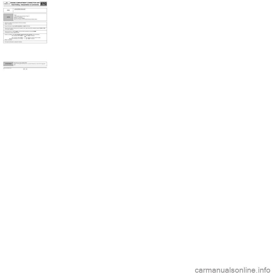
AC009
LOW-SPEED FAN UNIT
NOTESCheck:
–the condition and connection of fuse 11.
Replace it if necessary.
The fans must have stopped.
Make sure nothing is mechanically blocking the blade rotation.
Check the condition and connection of the fan connector.
Repair if necessary.
Ensure that there is a good earth connection on track 2 of the fan.
Check that the resistor in the fan unit (if it exists) is not in open circuit with a resistance equal to 0.69 ΩΩ Ω Ω
± 20%.
If not correct, replace it.
Check that there is a +12 V supply on the fan while controlled by command AC009.
If everything is correct, replace the fan.
If there is a problem, check the insulation against earth and continuity of the connections:
UPC connector PPM1 track 4 Track 1 of the fan
OR
UPC connector PPM1 track 4 Resistor in the fan unit (if it exists)
Resistance in the fan unit (if it exists) Track 1 of the fan
Repair if necessary.
If the fault is still present, contact the Techline.
AFTER REPAIRDeal with any other possible faults.
Switch off the ignition and carry out a road test followed by a test with the diagnostic
tool.
Page 47 of 56
87G - 47
ENGINE COMPARTMENT CONNECTION UNIT
Fault finding - Interpretation of commands
87G
V6 MR-372-J84-87G000$792_eng.mif
UPC
Vdiag No.: 44
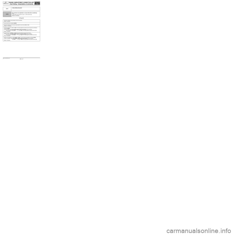
UPC type N2 AC010
HIGH-SPEED FAN UNIT
NOTESThis command is only applicable on versions fitted with air conditioning.
Check:
–the condition and connection of fuse 11 (UPC level N3 only).
Replace it if necessary.
Check the condition and connection of the fan connector.
Repair if necessary.
Ensure that the fan is properly earthed.
Check the resistance of the external high-speed fan control relay: 65 ΩΩ Ω Ω
± 10 ΩΩ Ω Ω
.
Replace it if necessary.
Check the presence of +12 V on track 1 of the high-speed fan external control relay when controlled by
command AC010.
If there is a fault, check the insulation against earth and continuity of the connection
UPC connector PPM2 track 3 Track 1 of the high-speed fan external control relay
Repair if necessary.
Check that there is earthing on track 2 of the high-speed fan external control relay.
If there is a fault, check the insulation against +12 V and continuity of the connection:
UPC connector PPM2 track 2 Track 2 of the high-speed fan external control relay
Repair if necessary.
Check for the presence of +12 V supply on track 1 of the fan while controlled by command AC010.
If there is a problem, check the insulation against earth and continuity of the connection:
Fan track 1 Track 5 of the high-speed fan external control relay
Repair if necessary.
Page 48 of 56
87G - 48
ENGINE COMPARTMENT CONNECTION UNIT
Fault finding - Interpretation of commands
87G
V6 MR-372-J84-87G000$792_eng.mif
UPC
Vdiag No.: 44
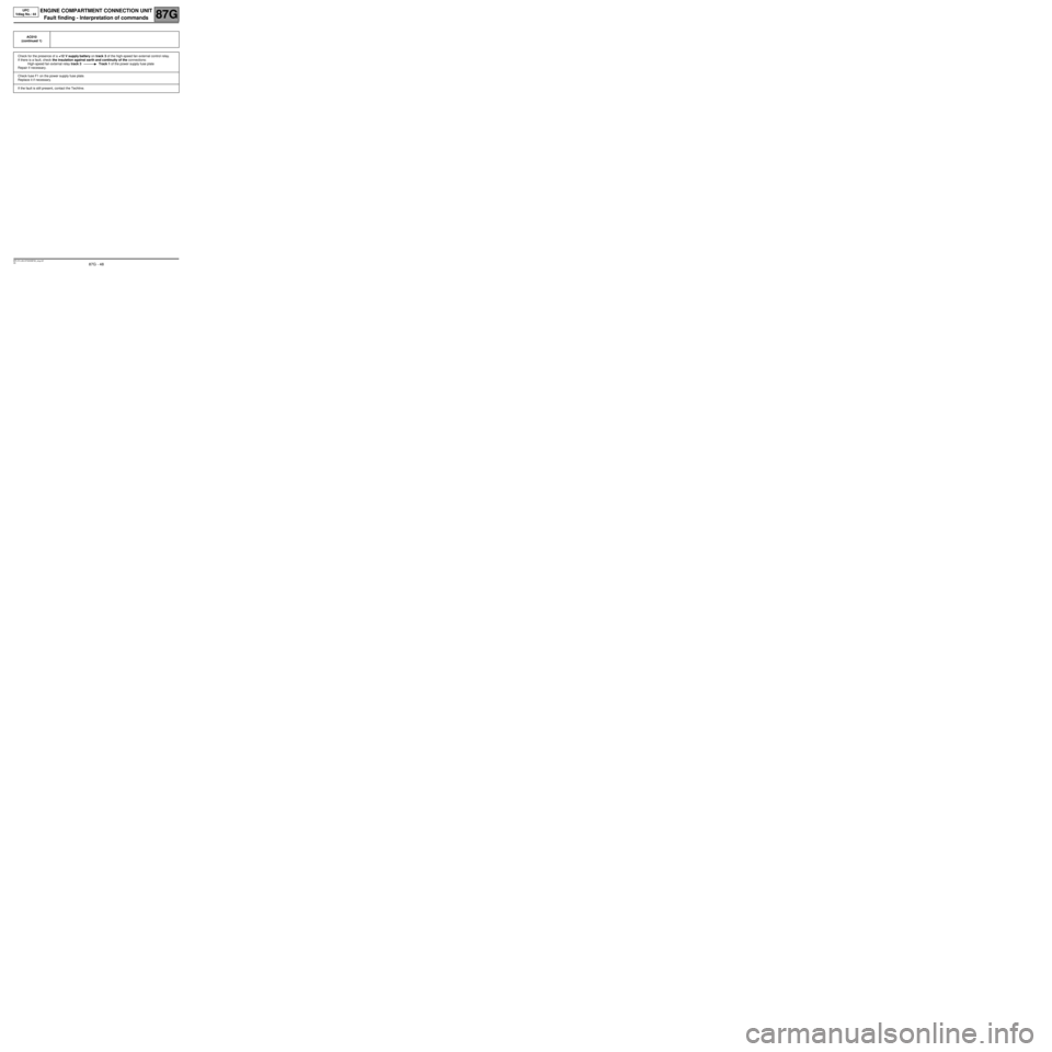
AC010
(continued 1)
Check for the presence of a +12 V supply battery on track 3 of the high-speed fan external control relay.
If there is a fault, check the insulation against earth and continuity of the connections:
High-speed fan external relay track 3 Track 1 of the power supply fuse plate
Repair if necessary.
Check fuse F1 on the power supply fuse plate.
Replace it if necessary.
If the fault is still present, contact the Techline.
Page 50 of 56
87G - 50
ENGINE COMPARTMENT CONNECTION UNIT
Fault finding - Interpretation of commands
87G
V6 MR-372-J84-87G000$792_eng.mif
UPC
Vdiag No.: 44
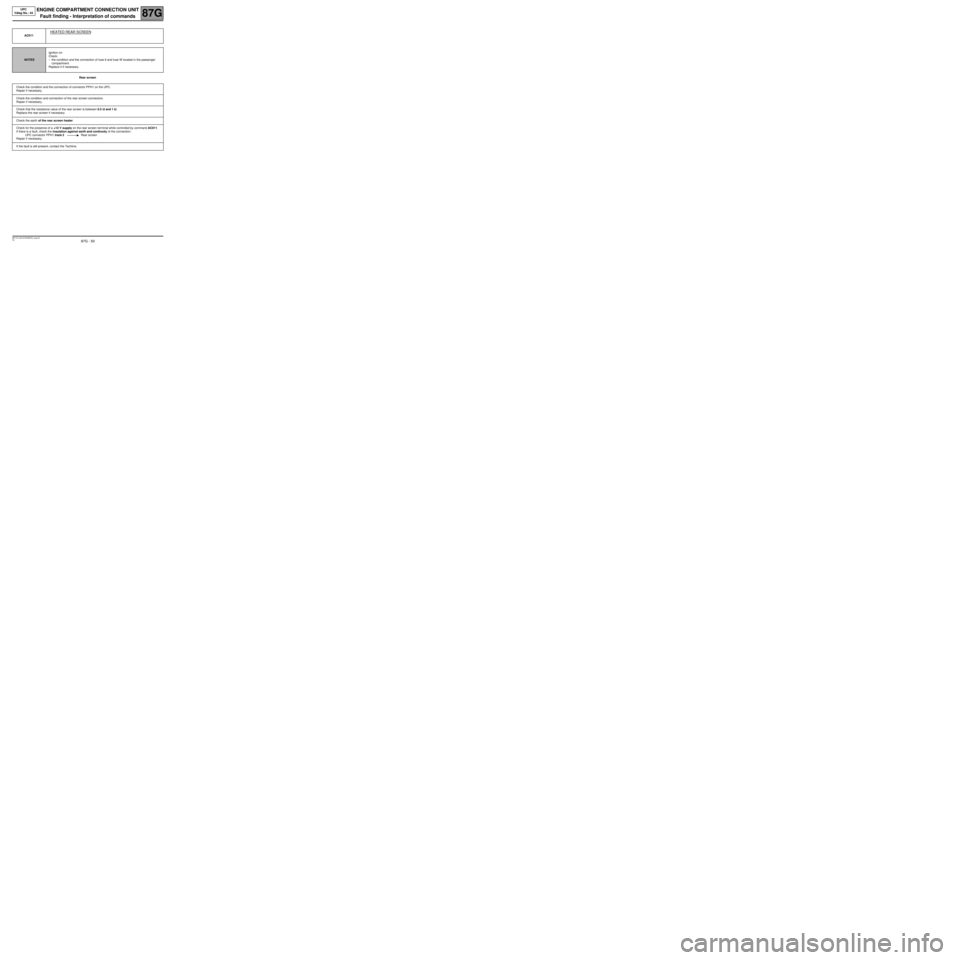
Rear screen AC011
HEATED REAR SCREEN
NOTESIgnition on
Check:
–the condition and the connection of fuse 6 and fuse W located in the passenger
compartment.
Replace it if necessary.
Check the condition and the connection of connector PPH1 on the UPC.
Repair if necessary.
Check the condition and connection of the rear screen connectors.
Repair if necessary.
Check that the resistance value of the rear screen is between 0.5 ΩΩ Ω Ω
and 1 ΩΩ Ω Ω
.
Replace the rear screen if necessary.
Check the earth of the rear screen heater.
Check for the presence of a +12 V supply on the rear screen terminal while controlled by command AC011.
If there is a fault, check the insulation against earth and continuity of the connection:
UPC connector PPH1 track 2 Rear screen
Repair if necessary.
If the fault is still present, contact the Techline.
Page 51 of 56
87G - 51
ENGINE COMPARTMENT CONNECTION UNIT
Fault finding - Interpretation of commands
87G
V6 MR-372-J84-87G000$792_eng.mif
UPC
Vdiag No.: 44
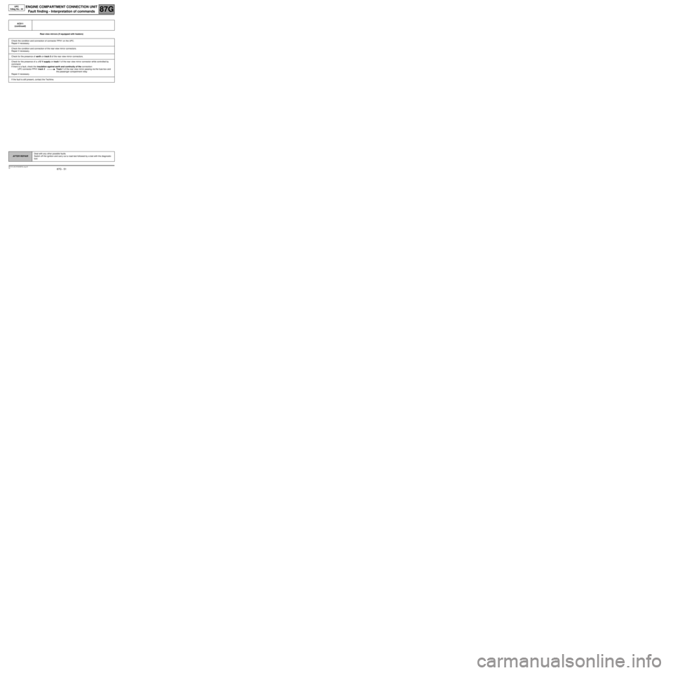
Rear-view mirrors (if equipped with heaters) AC011
(continued)
Check the condition and connection of connector PPH1 on the UPC.
Repair if necessary.
Check the condition and connection of the rear-view mirror connectors.
Repair if necessary.
Check for the presence of earth on track 5 of the rear view mirror connectors.
Check for the presence of a +12 V supply on track 1 of the rear view mirror connector while controlled by
command.
If there is a fault, check the insulation against earth and continuity of the connection:
UPC connector PPH1 track 2 Track 1 of the rear view mirror passing via the fuse box and
the passenger compartment relay
Repair if necessary.
If the fault is still present, contact the Techline.
AFTER REPAIRDeal with any other possible faults.
Switch off the ignition and carry out a road test followed by a test with the diagnostic
tool.
Page 54 of 56
87G - 54
ENGINE COMPARTMENT CONNECTION UNIT
Fault finding - Fault Finding Chart (ALP)
87G
V6 MR-372-J84-87G000$924_eng.mif
UPC
Vdiag No.: 44ENGINE COMPARTMENT CONNECTION UNIT
Fault finding - Fault Finding Chart (ALP)
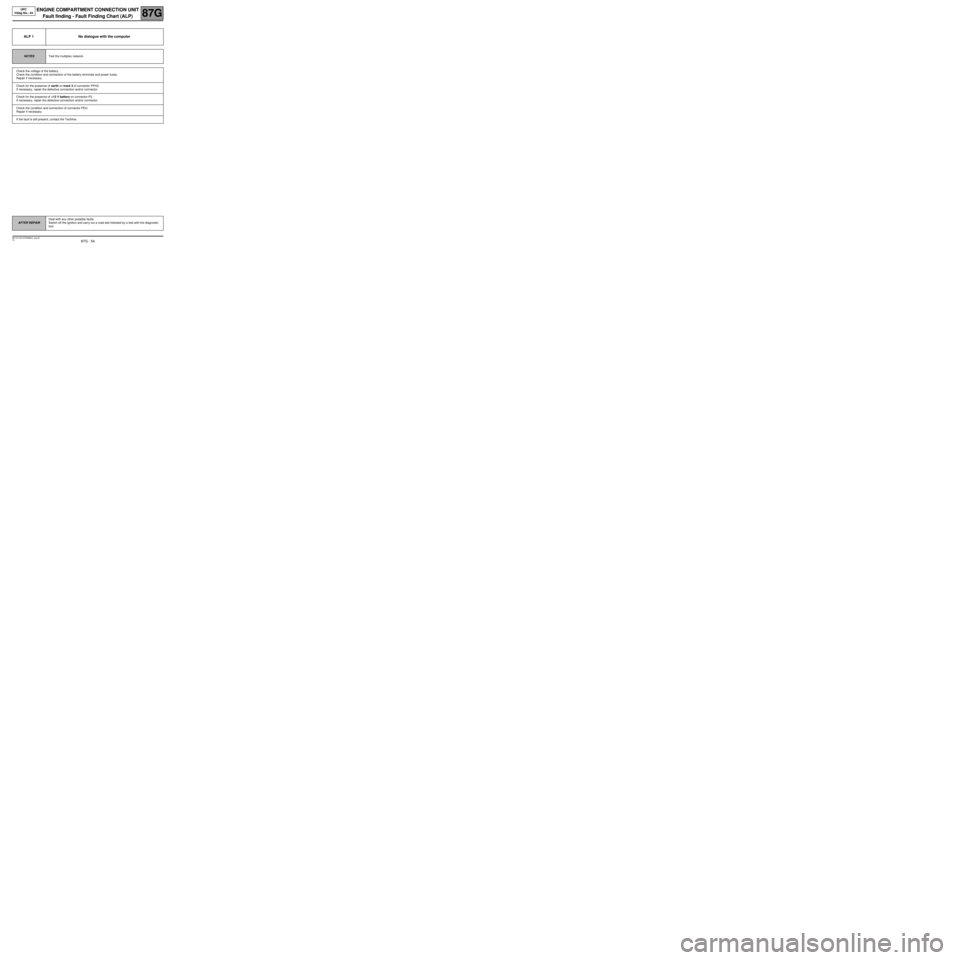
ALP 1 No dialogue with the computer
NOTESTest the multiplex network.
Check the voltage of the battery.
Check the condition and connection of the battery terminals and power fuses.
Repair if necessary.
Check for the presence of earth on track 3 of connector PPH2.
If necessary, repair the defective connection and/or connector.
Check for the presence of +12 V battery on connector P2.
If necessary, repair the defective connection and/or connector.
Check the condition and connection of connector PEH.
Repair if necessary.
If the fault is still present, contact the Techline.
AFTER REPAIRDeal with any other possible faults.
Switch off the ignition and carry out a road test followed by a test with the diagnostic
tool.
MR-372-J84-87G000$924_eng.mif