air condition RENAULT SCENIC 2010 J95 / 3.G Engine Compartment Connection Unit Workshop Manual
[x] Cancel search | Manufacturer: RENAULT, Model Year: 2010, Model line: SCENIC, Model: RENAULT SCENIC 2010 J95 / 3.GPages: 56
Page 3 of 56
87G - 3
ENGINE COMPARTMENT CONNECTION UNIT
Fault finding - Introduction
87G
V6 MR-372-J84-87G000$066_eng.mif
UPC
Vdiag No.: 44
Faults
Faults are declared as either present or stored (depending on whether they appeared in a certain context and have
disappeared since, or whether they remain present but have not been diagnosed within the current context).
The present or stored status of the fault should be taken into consideration when the diagnostic tool is used after
the + after ignition feed has been connected (without any of the system components being activated).
For a present fault, apply the procedure described in the Interpretation of faults section.
For a stored fault, note the faults displayed and apply the instructions in the Notes section.
If the fault is confirmed when the instructions in the Notes section are applied, the fault is present. Deal with the fault
If the fault is not confirmed, check:
–the electrical lines which correspond to the fault,
–the connectors on these lines (corrosion, bent pins, etc.),
–the resistance of the component detected as faulty,
–the condition of the wires (melted or split insulation, wear).
Conformity check
The aim of the conformity check is to check statuses and parameters that do not produce a fault display on the
diagnostic tool when they are inconsistent. Therefore, this phase is used to:
–carry out fault finding on faults that do not have a fault display, and which may correspond to a customer
complaint.
–check that the system is operating correctly and that there is no risk of a fault recurring after repair.
This section gives the fault finding procedures for statuses and parameters and the conditions for checking them.
If a status is not behaving normally or a parameter is outside the permitted tolerance values, consult the
corresponding fault finding page.
Customer complaints - Fault finding chart
If the test with the diagnostic tool is OK but the customer complaint is still present, the fault should be dealt with by
customer complaints.
A summary of the overall procedure to follow is provided on the following
page in the form of a flow chart.
Page 4 of 56
87G - 4
ENGINE COMPARTMENT CONNECTION UNIT
Fault finding - Introduction
87G
V6 MR-372-J84-87G000$066_eng.mif
UPC
Vdiag No.: 44
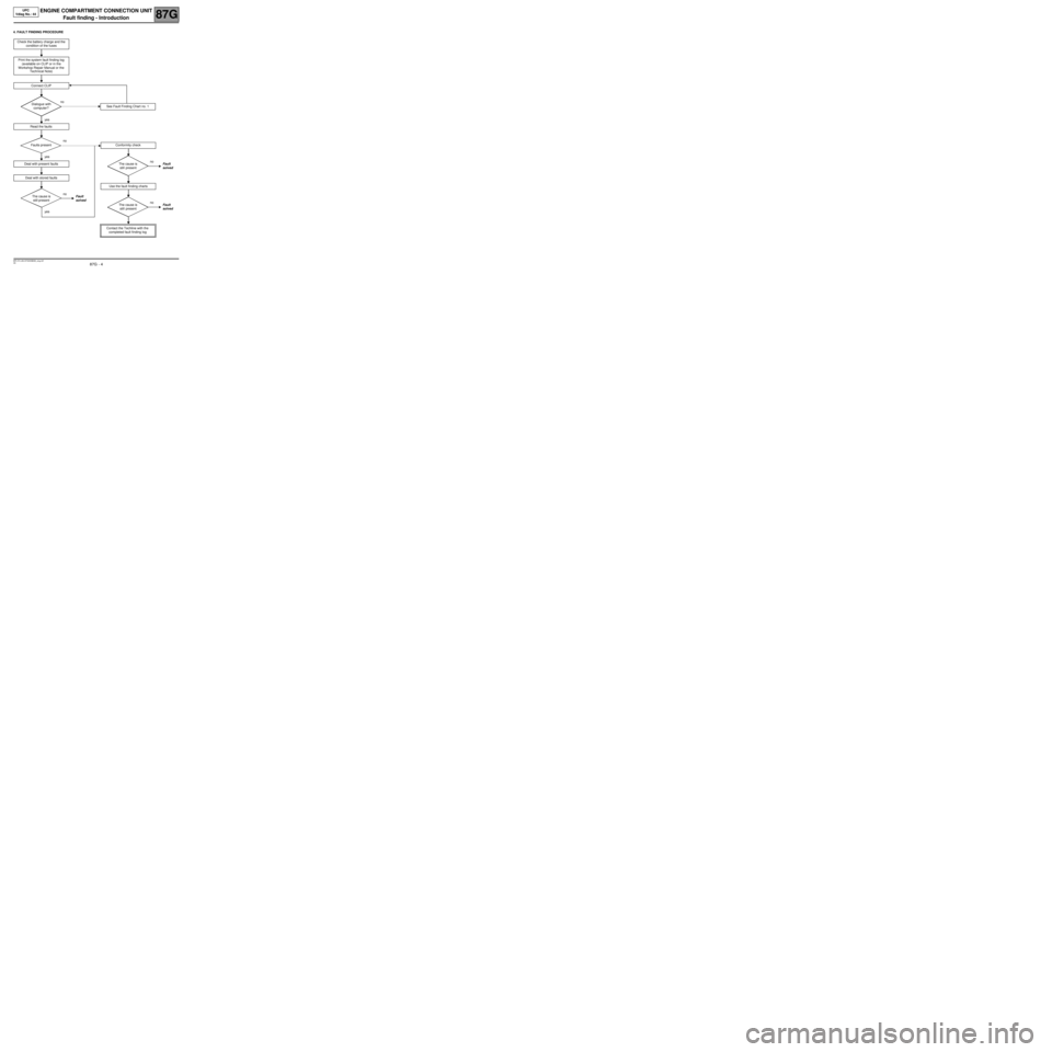
4. FAULT FINDING PROCEDURE
Check the battery charge and the
condition of the fuses
Print the system fault finding log
(available on CLIP or in the
Workshop Repair Manual or the
Technical Note)
Connect CLIP
no
Dialogue with
computer?
yes
Read the faults
no
Faults present
yes
Deal with present faults
Deal with stored faults
no
The cause is
still presentFault
solved
yes
See Fault Finding Chart no. 1
Conformity check
no
The cause is
still presentFault
solved
Use the fault finding charts
no
The cause is
still presentFault
solved
Contact the Techline with the
completed fault finding log
Page 7 of 56
87G - 7
ENGINE COMPARTMENT CONNECTION UNIT
Fault finding - System operation
87G
V6 MR-372-J84-87G000$132_eng.mif
UPC
Vdiag No.: 44ENGINE COMPARTMENT CONNECTION UNIT
Fault finding - System operation
1. GENERAL FUNCTIONING
The UPC particpates in the following functions:
–distributing and protecting the electrical power,
–keyless vehicles,
–wipers,
–lighting,
–de-icing,
–air conditioning,
–oil pressure detection.
Distributing and protecting electrical power
The main function of the UPC is to switch on and distribute part of the power in order to supply the vehicle systems,
actuators or computers.
Another part of the power supply distribution is housed in the Engine Interconnection Unit but is not controlled
electronically by the computer.
+12 V battery feed
The UPC receives energy from the battery via the 1 track screwed connector and redistributes +12 V around the
vehicle.
+ after ignition feed
The UCH requests the + APC via the multiplex network. When the UPC receives this request, it controls the APC
relay unconditionally.
Energy management
The computer transmits the signal to load the alternator on the multiplex network.
Keyless vehicle
In the Keyless vehicle function, the UPC participates in the start-up sub-function. The computer:
–receives the request to start up the UCH via the multiplex network,
–check that the start-up conditions have been met then controls the starter relay,
–can inhibit or turn off the starter relay command by means of a forbid start-up signal transmitted by the
injection computer on the multiplex network.
Air conditioning
For the operation of this function and the role of the UPC in setting up this function (see 62A, Air conditioning,
Function architecture and General functioning mode).
Cold loop
The computer receives the compressor switch-on request from the injection via the multiplex network.
The computer controls the compressor clutch activation relay.
Heating
The computer also controls the de-icing of the rear tailgate window and the electric rear view mirrors.
Fan assembly
When prompted for the engine check request, the UPC supplies the GMV with power.
MR-372-J84-87G000$132_eng.mif
Page 15 of 56
87G - 15
ENGINE COMPARTMENT CONNECTION UNIT
Fault finding - Interpretation of faults
87G
V6 MR-372-J84-87G000$462_eng.mif
UPC
Vdiag No.: 44
DF009
PRESENT
+ APC CIRCUIT
DEF : Consistency
NOTESNone.
Check the voltage of the battery.
Check that ET026 + ignition status is consistent
Check the condition of the fuses on the battery positive terminal.
Repair if necessary.
Check the status and the connection of the + battery on the UPC mounting and on the P2 connector.
Repair if necessary.
With the ignition turned off, check that there is no +12 V supply on track 6 of UPC connector PPM2
If the +12 V feed is present, disconnect the following fuses one by one in order to isolate the faulty track:
–fuse 5C (track 6 connector PPM2),
–fuse 5D (track 1 connector PEH),
–fuse 5E (track 10 connector PPH2),
–fuse 5F (track 11 connector PPH2),
–fuse 5G (track 7 connector PPM2),
–fuse 5H (track 10 connector PPM2).
Using an electrical diagram, check the insulation against +12 V, of the connection between the track which
the UPC detected as faulty and the computers or consumers linked to this track.
With the ignition on, check for the presence of +12 V on one of the following UPC tracks:
–track 1 of connector PEH
–tracks 6, 7 and 10 of connector PPM2
–tracks 10 and 11 of connector PPH2
If the fault is still present, contact the Techline.
AFTER REPAIRClear the computer memory.
Turn the ignition off and then on again, then run a new check using the fault finding tool.
Page 18 of 56
87G - 18
ENGINE COMPARTMENT CONNECTION UNIT
Fault finding - Conformity check
87G
V6 MR-372-J84-87G000$528_eng.mif
UPC
Vdiag No.: 44
AIR CONDITIONING: Heating
AIR CONDITIONING: Cold loop
NOTESOnly check conformity after a complete check using the diagnostic tool.
Test conditions: Engine stopped, ignition on.
Order FunctionParameter or Status
checked or Action Display and notes Fault finding
1StartingPR010:AlternatorIn %
The value must be
fixed and greater than
98%
Refer to the relevant fault
finding procedure in the
event of a fault.
AC011:Rear
windscreen
de-icingThe rear window
heating resistors and
the door mirrors (if the
vehicle is fitted with
heated door mirrors)
must be supplied with
power and heated.
Order FunctionParameter or Status
checked or Action Display and notes Fault finding
1Fan assemblyAC009:Low speed fan
unitIt must be possible to
hear the fan running at
low speed.
Refer to the relevant fault
finding procedure in the
event of a fault. AC010:High speed fan
unitIt must be possible to
hear the fan running at
high speed
This command cannot
be used on vehicles
not fitted with climate
control
2Air conditioningAC008:Compressor
commandThe compressor clutch
must be heard (the
compressor command
is not permitted when
the engine is running)
Page 23 of 56
87G - 23
ENGINE COMPARTMENT CONNECTION UNIT
Fault finding - Conformity check
87G
V6 MR-372-J84-87G000$528_eng.mif
UPC
Vdiag No.: 44
AIR CONDITIONING: Heating
AIR CONDITIONING: Cold loop
NOTESOnly check conformity after a complete check using the diagnostic tool.
Condition for carrying out the operation: the engine must be running.
Order FunctionParameter or Status
checked or Action Display and notes Fault finding
1StartingPR010:AlternatorIn %
The value varies
according to electricity
consumption.
Refer to the relevant fault
finding method in the event
of a fault.
AC011:Rear
windscreen de-
icingThe heating resistance
for the rear window
and the door mirrors
(if the vehicle is fitted
with door mirrors) must
be supplied with power
and supply heat
Order FunctionParameter or Status
checked or Action Display and notes Fault finding
1Fan assemblyAC009:Low speed fan
unitThe fan must be heard
running at low speed
Refer to the relevant fault
finding procedure in the
event of a fault. AC010:High speed fan
unitThe fan must be heard
running at a high
speed
This command cannot
be used on vehicles
which are not fitted
with climate control
2Air conditioningAC008:Compressor
control(this command is not
permitted when the
engine is running)
Page 28 of 56

87G - 28
ENGINE COMPARTMENT CONNECTION UNIT
Fault finding - Interpretation of statuses
87G
V6 MR-372-J84-87G000$660_eng.mif
UPC
Vdiag No.: 44
ET002
WINDSCREEN WIPER PROTECTION
NOTESBefore starting, check the operation of the windscreen wiper motor by running
commands AC005 Windscreen wiper at low speed and AC006 Windscreen wiper
at high speedand then check the park position using command AC012 Windscreen
wiper park position.
These statuses are listed in the order of severity or persistance of incorrect wiper
operation.
–if the status is INACTIVE, the wiper function is normal.
–If the status is LOW SPEED, the UPC has detected an abnormal wiper operation on
the higher speed setting for more than 6 seconds (the wiper has stuck or is blocked);
windscreen wiping is therefore forced to operate on the lower speed setting when
the higher speed setting is requested,
–If the status is INTERMITTENT, the wiper function is stopped for 10 seconds
following the detection and persistence of the fault (restrained or blocked),
–If the status is BLOCKED, wiping stops 30 seconds after the malfunction has lasted
for more than 2 minutes.
The status returns to INACTIVE, once the UCH requests a new wiping instruction (by
following the movement of the wiper stalk or by request from the rain sensor).
Make sure that nothing is mechanically blocking movement of the wiper blades (blades stuck, condition and
assembly of the wiper mechanism linkage and no object interfering with the motion of the device).
Check that the wiper mechanism is not seized.
Repair if necessary.
Check the status and the connection of connectors PPH2 and PEH on the UPC and of the windscreen wiper
motor.
Repair if necessary.
Page 34 of 56
87G - 34
ENGINE COMPARTMENT CONNECTION UNIT
Fault finding - Interpretation of statuses
87G
V6 MR-372-J84-87G000$660_eng.mif
UPC
Vdiag No.: 44
ET010
CONDITIONS FOR STARTING THE ENGINE SATISFIED
NOTESNo particular instructions.
In the Keyless vehicle function, check that the starting conditions are met.
The UPC participates in the engine start function by managing the switches on the gearbox.
Check the operation of the gearbox switches using statuses ET004 Reverse gear selected and ET005
Manual gearbox gear lever position then run fault finding on UCH start and engine management functions.
If the conditions have been satisfied and the starter does not work, refer to ALP 2.
If the fault is still present, contact the Techline.
AFTER REPAIRDeal with any other possible faults.
Switch off the ignition and carry out a road test followed by a test with the diagnostic
tool.
Page 36 of 56
87G - 36
ENGINE COMPARTMENT CONNECTION UNIT
Fault finding - Interpretation of commands
87G
V6 MR-372-J84-87G000$792_eng.mif
UPC
Vdiag No.: 44ENGINE COMPARTMENT CONNECTION UNIT
Fault finding - Interpretation of commands
Without xenon lights AC001
MAIN BEAM HEADLIGHTS
NOTESCheck:
–the status and the connection of fuses 8A and 8B on the UPC,
–the status of the bulbs.
Replace them, if necessary.
Check the status and the connection of connector PPA and the fuses on the UPC.
Repair if necessary.
Check the condition and connection of the headlight connectors.
Repair if necessary.
Check the presence of earth on the connection R9 and then on track 1 of the headlight connector.
Repair if necessary.
Check the presence of +12 V on track 4 of the headlights when these are controlled by command AC001.
If everything is fine, replace the bulbs.
If there is a problem, check the insulation against earth and the continuity between the connections:
UPC connector PPA track 3 Left headlight track 4
UPC connector PPA track 4 Right headlight track 4
Repair if necessary.
If the fault is still present, contact the Techline.
MR-372-J84-87G000$792_eng.mif
Page 37 of 56
87G - 37
ENGINE COMPARTMENT CONNECTION UNIT
Fault finding - Interpretation of commands
87G
V6 MR-372-J84-87G000$792_eng.mif
UPC
Vdiag No.: 44
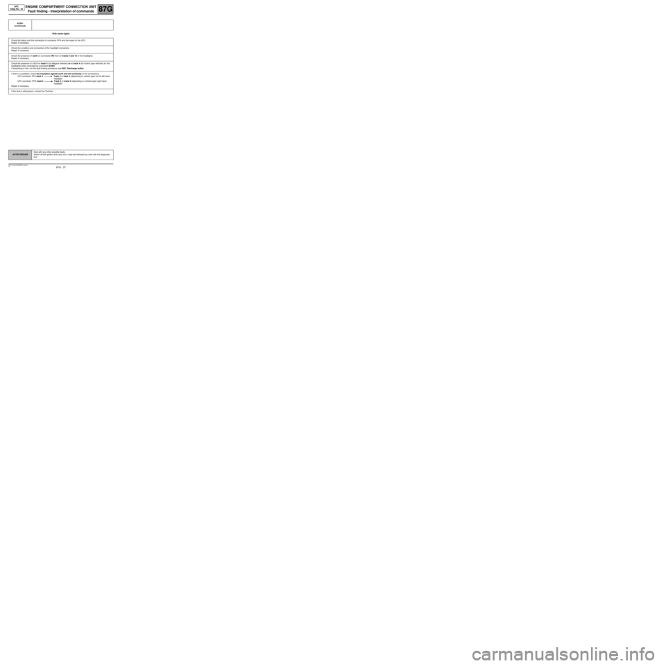
With xenon lights AC001
(continued)
Check the status and the connection of connector PPA and the fuses on the UPC.
Repair if necessary.
Check the condition and connection of the headlight connectors.
Repair if necessary.
Check the presence of earth on connection R9 then on tracks 4 and 10 of the headlights.
Repair if necessary.
Check the presence of +12 V on track 5 (for Mégane vehicles) or on track 4 (for Scénic type vehicles) for the
headlights when controlled by command AC001.
If everything is fine, run the fault finding procedure (see 80C, Discharge bulbs).
If there is a problem, check the insulation against earth and the continuity of the connections:
UPC connector PPA track 3 Track 5 or track 4 (depending on vehicle type) for the left-hand
headlight
UPC connector PPA track 4 Track 5 or track 4 (depending on vehicle type) right-hand
headlight
Repair if necessary.
If the fault is still present, contact the Techline.
AFTER REPAIRDeal with any other possible faults.
Switch off the ignition and carry out a road test followed by a test with the diagnostic
tool.