ignition RENAULT SCENIC 2010 J95 / 3.G Engine Compartment Connection Unit Workshop Manual
[x] Cancel search | Manufacturer: RENAULT, Model Year: 2010, Model line: SCENIC, Model: RENAULT SCENIC 2010 J95 / 3.GPages: 56
Page 2 of 56

87G - 2
ENGINE COMPARTMENT CONNECTION UNIT
Fault finding - Introduction
87G
V6 MR-372-J84-87G000$066_eng.mif
187G
UPC
Vdiag No.: 44ENGINE COMPARTMENT CONNECTION UNIT
Fault finding - Introduction
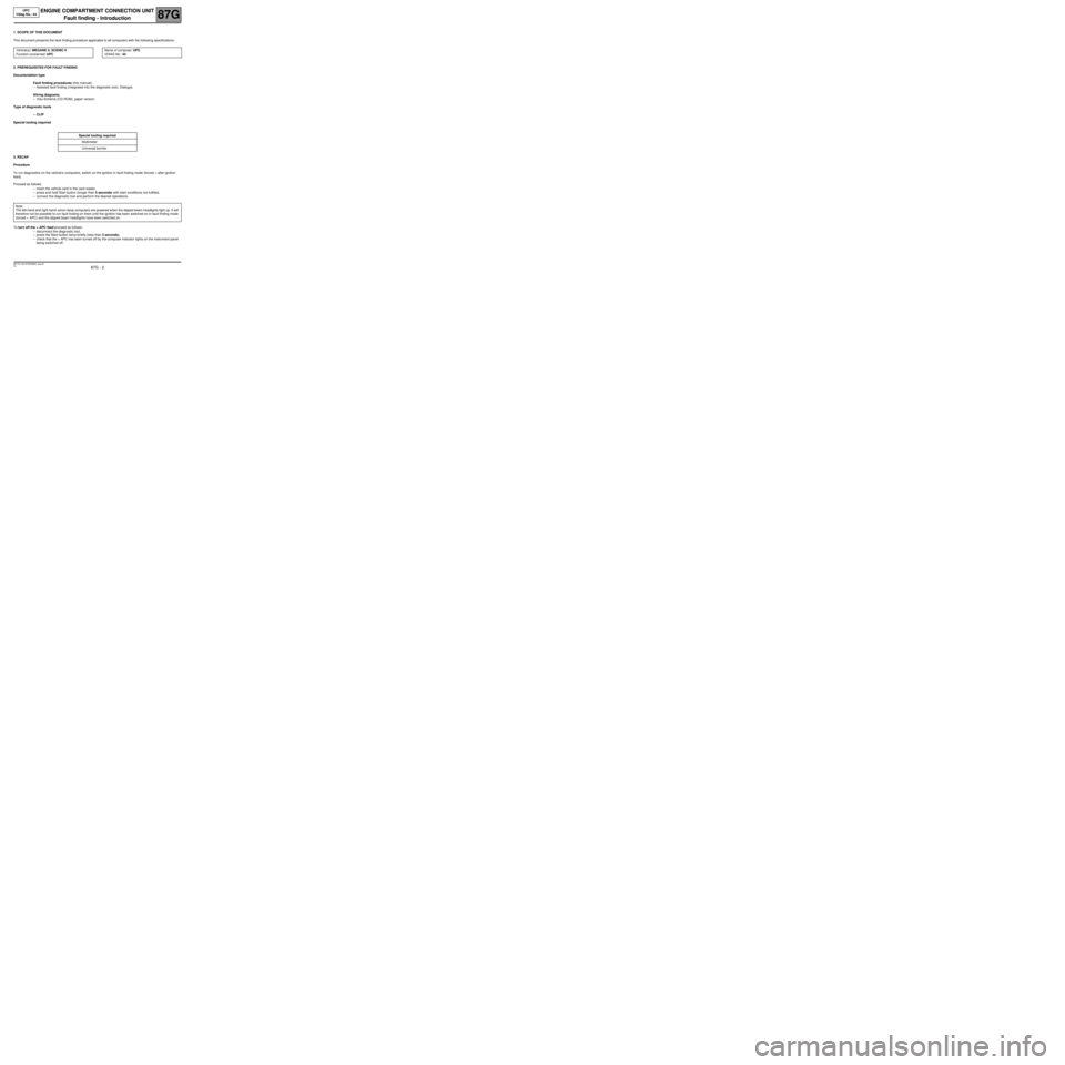
1. SCOPE OF THIS DOCUMENT
This document presents the fault finding procedure applicable to all computers with the following specifications:
2. PREREQUISITES FOR FAULT FINDING
Documentation type
Fault finding procedures (this manual):
–Assisted fault finding (integrated into the diagnostic tool), Dialogys.
Wiring diagrams:
–Visu-Schéma (CD-ROM), paper version.
Type of diagnostic tools
–CLIP
Special tooling required
3. RECAP
Procedure
To run diagnostics on the vehicle's computers, switch on the ignition in fault finding mode (forced + after ignition
feed).
Proceed as follows:
–insert the vehicle card in the card reader,
–press and hold Start button (longer than 5 seconds) with start conditions not fulfilled,
–connect the diagnostic tool and perform the desired operations.
To turn off the + APC feed proceed as follows:
–disconnect the diagnostic tool,
–press the Start button twice briefly (less than 3 seconds),
–check that the + APC has been turned off by the computer indicator lights on the instrument panel
being switched off. Vehicle(s): MEGANE II, SCENIC II
Function concerned: UPCName of computer: UPC
VDIAG No.: 44
Special tooling required
Multimeter
Universal bornier
Note:
The left-hand and right-hand xenon lamp computers are powered when the dipped beam headlights light up. It will
therefore not be possible to run fault finding on them until the ignition has been switched on in fault finding mode
(forced + APC) and the dipped beam headlights have been switched on.
MR-372-J84-87G000$066_eng.mif
Page 3 of 56

87G - 3
ENGINE COMPARTMENT CONNECTION UNIT
Fault finding - Introduction
87G
V6 MR-372-J84-87G000$066_eng.mif
UPC
Vdiag No.: 44
Faults
Faults are declared as either present or stored (depending on whether they appeared in a certain context and have
disappeared since, or whether they remain present but have not been diagnosed within the current context).
The present or stored status of the fault should be taken into consideration when the diagnostic tool is used after
the + after ignition feed has been connected (without any of the system components being activated).
For a present fault, apply the procedure described in the Interpretation of faults section.
For a stored fault, note the faults displayed and apply the instructions in the Notes section.
If the fault is confirmed when the instructions in the Notes section are applied, the fault is present. Deal with the fault
If the fault is not confirmed, check:
–the electrical lines which correspond to the fault,
–the connectors on these lines (corrosion, bent pins, etc.),
–the resistance of the component detected as faulty,
–the condition of the wires (melted or split insulation, wear).
Conformity check
The aim of the conformity check is to check statuses and parameters that do not produce a fault display on the
diagnostic tool when they are inconsistent. Therefore, this phase is used to:
–carry out fault finding on faults that do not have a fault display, and which may correspond to a customer
complaint.
–check that the system is operating correctly and that there is no risk of a fault recurring after repair.
This section gives the fault finding procedures for statuses and parameters and the conditions for checking them.
If a status is not behaving normally or a parameter is outside the permitted tolerance values, consult the
corresponding fault finding page.
Customer complaints - Fault finding chart
If the test with the diagnostic tool is OK but the customer complaint is still present, the fault should be dealt with by
customer complaints.
A summary of the overall procedure to follow is provided on the following
page in the form of a flow chart.
Page 7 of 56

87G - 7
ENGINE COMPARTMENT CONNECTION UNIT
Fault finding - System operation
87G
V6 MR-372-J84-87G000$132_eng.mif
UPC
Vdiag No.: 44ENGINE COMPARTMENT CONNECTION UNIT
Fault finding - System operation
1. GENERAL FUNCTIONING
The UPC particpates in the following functions:
–distributing and protecting the electrical power,
–keyless vehicles,
–wipers,
–lighting,
–de-icing,
–air conditioning,
–oil pressure detection.
Distributing and protecting electrical power
The main function of the UPC is to switch on and distribute part of the power in order to supply the vehicle systems,
actuators or computers.
Another part of the power supply distribution is housed in the Engine Interconnection Unit but is not controlled
electronically by the computer.
+12 V battery feed
The UPC receives energy from the battery via the 1 track screwed connector and redistributes +12 V around the
vehicle.
+ after ignition feed
The UCH requests the + APC via the multiplex network. When the UPC receives this request, it controls the APC
relay unconditionally.
Energy management
The computer transmits the signal to load the alternator on the multiplex network.
Keyless vehicle
In the Keyless vehicle function, the UPC participates in the start-up sub-function. The computer:
–receives the request to start up the UCH via the multiplex network,
–check that the start-up conditions have been met then controls the starter relay,
–can inhibit or turn off the starter relay command by means of a forbid start-up signal transmitted by the
injection computer on the multiplex network.
Air conditioning
For the operation of this function and the role of the UPC in setting up this function (see 62A, Air conditioning,
Function architecture and General functioning mode).
Cold loop
The computer receives the compressor switch-on request from the injection via the multiplex network.
The computer controls the compressor clutch activation relay.
Heating
The computer also controls the de-icing of the rear tailgate window and the electric rear view mirrors.
Fan assembly
When prompted for the engine check request, the UPC supplies the GMV with power.
MR-372-J84-87G000$132_eng.mif
Page 11 of 56

87G - 11
ENGINE COMPARTMENT CONNECTION UNIT
Fault finding - Configurations and programming87G
V6 MR-372-J84-87G000$330_eng.mif
UPC
Vdiag No.: 44ENGINE COMPARTMENT CONNECTION UNIT
Fault finding - Configurations and programming
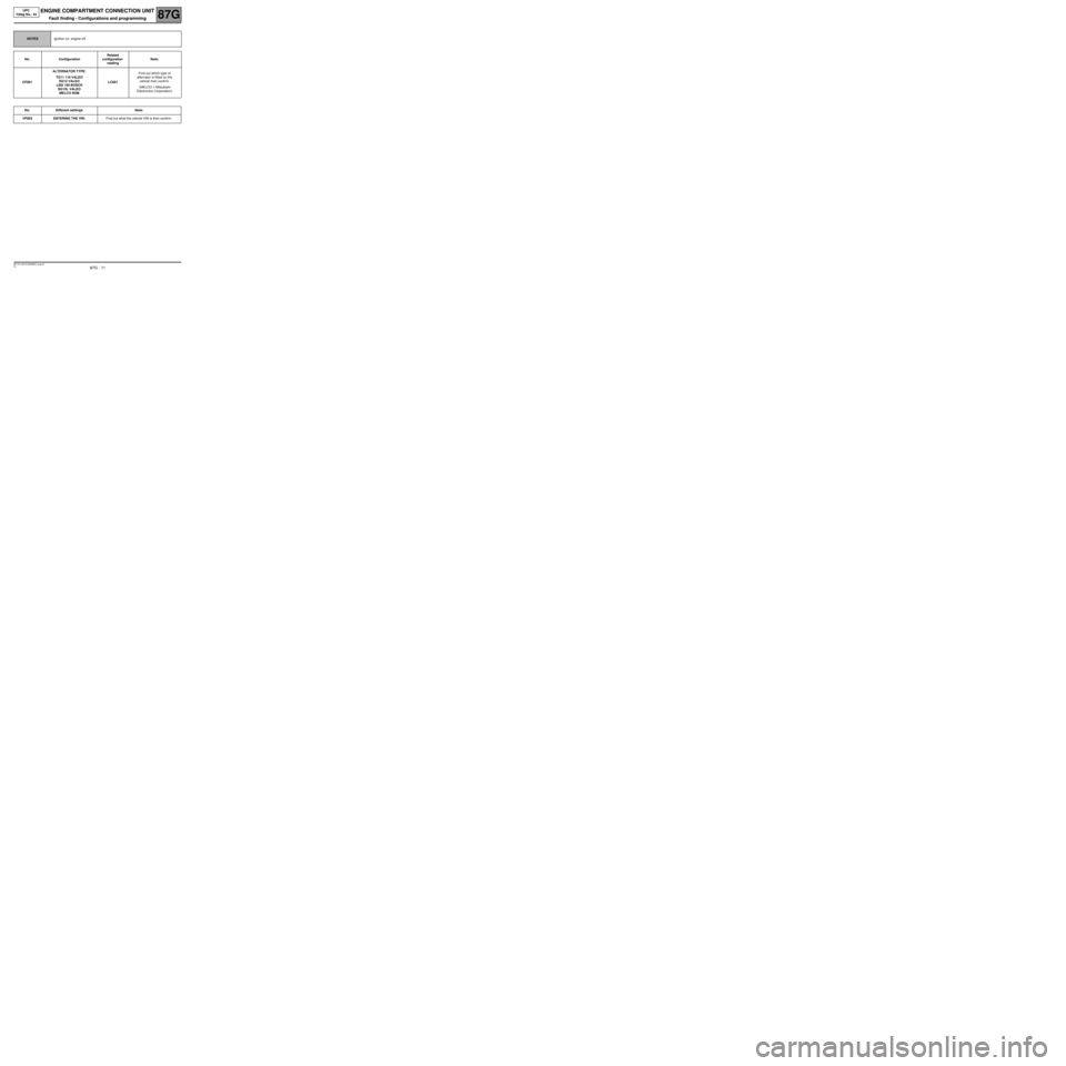
NOTESIgnition on, engine off.
No. ConfigurationRelated
configuration
readingNote:
CF001ALTERNATOR TYPE:
TG11 110 VALEO
SG12 VALEO
LIE8 150 BOSCH
SG15L VALEO
MELCO 8GMLC001Find out which type of
alternator is fitted on the
vehicle then confirm.
(MELCO = Mitsubishi
Electronics Corporation)
No. Different settings Note:
VP003 ENTERING THE VIN:Find out what the vehicle VIN is then confirm.
MR-372-J84-87G000$330_eng.mif
Page 12 of 56

87G - 12
ENGINE COMPARTMENT CONNECTION UNIT
Fault finding - Summary of faults
87G
V6 MR-372-J84-87G000$396_eng.mif
UPC
Vdiag No.: 44ENGINE COMPARTMENT CONNECTION UNIT
Fault finding - Summary of faults
Tool fault Associated DTC Diagnostic tool title
DF002 9210 HIGH SPEED FAN RELAY CONTROL CIRCUIT
DF005 920E INTERNAL ELECTRONIC FAULT
DF009 920D + IGNITION CIRCUIT
MR-372-J84-87G000$396_eng.mif
Page 13 of 56

87G - 13
ENGINE COMPARTMENT CONNECTION UNIT
Fault finding - Interpretation of faults
87G
V6 MR-372-J84-87G000$462_eng.mif
UPC
Vdiag No.: 44ENGINE COMPARTMENT CONNECTION UNIT
Fault finding - Interpretation of faults
DF002
PRESENT
HIGH SPEED FAN RELAY CONTROL CIRCUIT
CC.1 : Short circuit to +12 V
NOTESSpecial notes:
The function is inhibited when the fault is present.
Reactivating the function via a new ignition request.
Measure the resistance between tracks 1 and 2.
If the resistance is not 65 ΩΩ Ω Ω
± 10 ΩΩ Ω Ω
, replace the relay.
Take the relay out and make sure that it is insulated from the +12 V for the connection:
UPC connector PPM2 track 2 Track 2 of the fan relay connector
Repair if necessary.
If the fault is still present, check for the absence of +12 V on track 2 of the UPC connector PPM2.
If +12 V is present, contact the Techline.
AFTER REPAIRClear the computer memory.
Turn the ignition off and then on again, then run a new check using the fault finding tool
MR-372-J84-87G000$462_eng.mif
Page 14 of 56

87G - 14
ENGINE COMPARTMENT CONNECTION UNIT
Fault finding - Interpretation of faults
87G
V6 MR-372-J84-87G000$462_eng.mif
UPC
Vdiag No.: 44
D F005
PRESENT
INTERNAL ELECTRONIC FAULT
DEF : Internal electronic fault
NOTESNone.
Disconnect the battery for 30 seconds then reconnect it.
If the fault is still present, contact the Techline.
AFTER REPAIRClear the computer memory.
Turn the ignition off and then on again, then run a new check using the fault finding tool.
Page 15 of 56

87G - 15
ENGINE COMPARTMENT CONNECTION UNIT
Fault finding - Interpretation of faults
87G
V6 MR-372-J84-87G000$462_eng.mif
UPC
Vdiag No.: 44
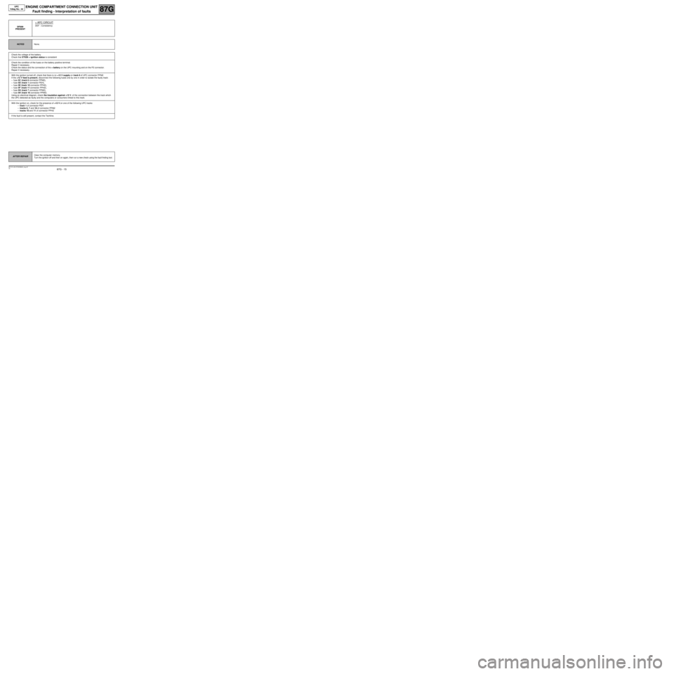
DF009
PRESENT
+ APC CIRCUIT
DEF : Consistency
NOTESNone.
Check the voltage of the battery.
Check that ET026 + ignition status is consistent
Check the condition of the fuses on the battery positive terminal.
Repair if necessary.
Check the status and the connection of the + battery on the UPC mounting and on the P2 connector.
Repair if necessary.
With the ignition turned off, check that there is no +12 V supply on track 6 of UPC connector PPM2
If the +12 V feed is present, disconnect the following fuses one by one in order to isolate the faulty track:
–fuse 5C (track 6 connector PPM2),
–fuse 5D (track 1 connector PEH),
–fuse 5E (track 10 connector PPH2),
–fuse 5F (track 11 connector PPH2),
–fuse 5G (track 7 connector PPM2),
–fuse 5H (track 10 connector PPM2).
Using an electrical diagram, check the insulation against +12 V, of the connection between the track which
the UPC detected as faulty and the computers or consumers linked to this track.
With the ignition on, check for the presence of +12 V on one of the following UPC tracks:
–track 1 of connector PEH
–tracks 6, 7 and 10 of connector PPM2
–tracks 10 and 11 of connector PPH2
If the fault is still present, contact the Techline.
AFTER REPAIRClear the computer memory.
Turn the ignition off and then on again, then run a new check using the fault finding tool.
Page 16 of 56

87G - 16
ENGINE COMPARTMENT CONNECTION UNIT
Fault finding - Conformity check
87G
V6 MR-372-J84-87G000$528_eng.mif
UPC
Vdiag No.: 44ENGINE COMPARTMENT CONNECTION UNIT
Fault finding - Conformity check
MAIN SCREEN
NOTESOnly check conformity after a complete check using the diagnostic tool.
Test conditions: Engine stopped, ignition on.
Order FunctionParameter or Status
checked or Action Display and notes Fault finding
1Charging circuitET001:Battery warning
lightLIT
In the event of a fault, refer to
the relevant fault finding
method. 2Oil pressure
contactET027:Oil pressure
contactCLOSED
3GearboxET004:Reverse gear
engagedYES
NO
MR-372-J84-87G000$528_eng.mif
Page 17 of 56

87G - 17
ENGINE COMPARTMENT CONNECTION UNIT
Fault finding - Conformity check
87G
V6 MR-372-J84-87G000$528_eng.mif
UPC
Vdiag No.: 44
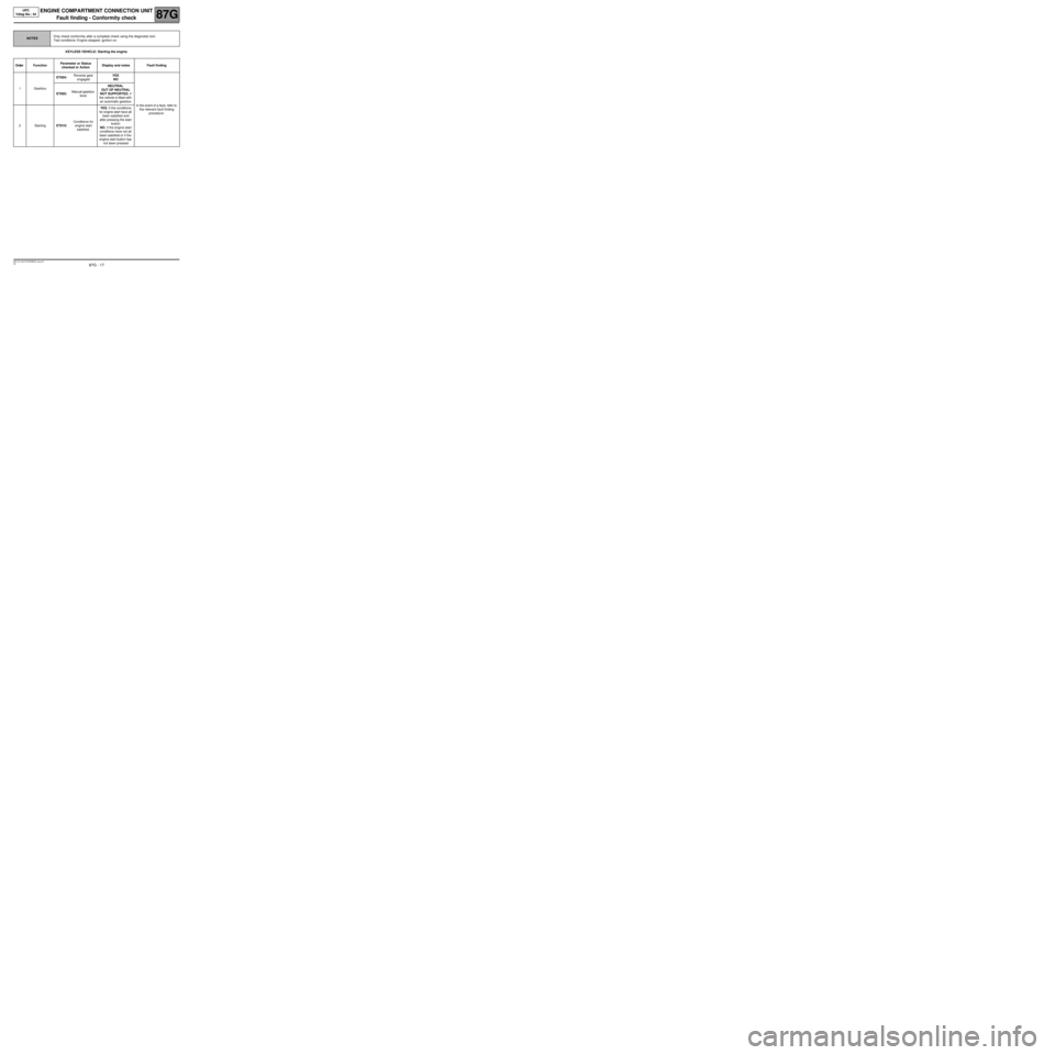
KEYLESS VEHICLE: Starting the engine
NOTESOnly check conformity after a complete check using the diagnostic tool.
Test conditions: Engine stopped, ignition on.
Order FunctionParameter or Status
checked or Action Display and notes Fault finding
1GearboxET004:Reverse gear
engagedYES
NO
In the event of a fault, refer to
the relevant fault finding
procedure. ET005:Manual gearbox
leverNEUTRAL
OUT OF NEUTRAL
NOT SUPPORTED, if
the vehicle is fitted with
an automatic gearbox
2StartingET010:Conditions for
engine start
satisfied.YES, if the conditions
for engine start have all
been satisfied and
after pressing the start
button
NO, if the engine start
conditions have not all
been satisfied or if the
engine start button has
not been pressed