ignition RENAULT SCENIC 2010 J95 / 3.G Engine Compartment Connection Unit User Guide
[x] Cancel search | Manufacturer: RENAULT, Model Year: 2010, Model line: SCENIC, Model: RENAULT SCENIC 2010 J95 / 3.GPages: 56
Page 18 of 56
87G - 18
ENGINE COMPARTMENT CONNECTION UNIT
Fault finding - Conformity check
87G
V6 MR-372-J84-87G000$528_eng.mif
UPC
Vdiag No.: 44
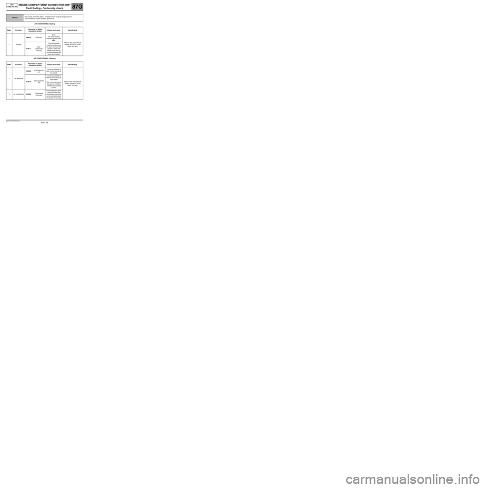
AIR CONDITIONING: Heating
AIR CONDITIONING: Cold loop
NOTESOnly check conformity after a complete check using the diagnostic tool.
Test conditions: Engine stopped, ignition on.
Order FunctionParameter or Status
checked or Action Display and notes Fault finding
1StartingPR010:AlternatorIn %
The value must be
fixed and greater than
98%
Refer to the relevant fault
finding procedure in the
event of a fault.
AC011:Rear
windscreen
de-icingThe rear window
heating resistors and
the door mirrors (if the
vehicle is fitted with
heated door mirrors)
must be supplied with
power and heated.
Order FunctionParameter or Status
checked or Action Display and notes Fault finding
1Fan assemblyAC009:Low speed fan
unitIt must be possible to
hear the fan running at
low speed.
Refer to the relevant fault
finding procedure in the
event of a fault. AC010:High speed fan
unitIt must be possible to
hear the fan running at
high speed
This command cannot
be used on vehicles
not fitted with climate
control
2Air conditioningAC008:Compressor
commandThe compressor clutch
must be heard (the
compressor command
is not permitted when
the engine is running)
Page 19 of 56
87G - 19
ENGINE COMPARTMENT CONNECTION UNIT
Fault finding - Conformity check
87G
V6 MR-372-J84-87G000$528_eng.mif
UPC
Vdiag No.: 44
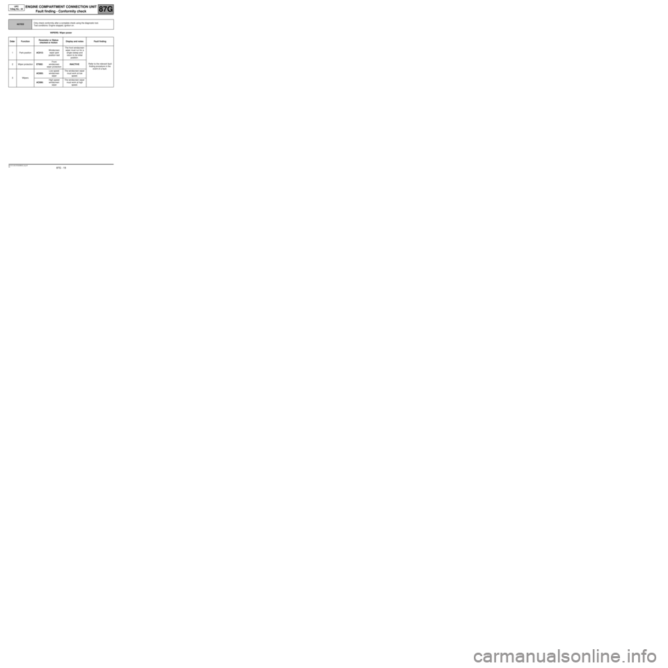
WIPERS: Wiper power
NOTESOnly check conformity after a complete check using the diagnostic tool.
Test conditions: Engine stopped, ignition on.
Order FunctionParameter or Status
checked or Action Display and notes Fault finding
1Park positionAC012:Windscreen
wiper park
position testThe front windscreen
wiper must run for a
single sweep and
return to its initial
position.
Refer to the relevant fault
finding procedure in the
event of a fault. 2Wiper protectionET002:Front
windscreen
wiper protectionINACTIVE
3WipersAC005:Low-speed
windscreen
wiperThe windscreen wiper
must work at low
speed.
AC006:High-speed
windscreen
wiperThe windscreen wiper
must work at high
speed.
Page 20 of 56
87G - 20
ENGINE COMPARTMENT CONNECTION UNIT
Fault finding - Conformity check
87G
V6 MR-372-J84-87G000$528_eng.mif
UPC
Vdiag No.: 44
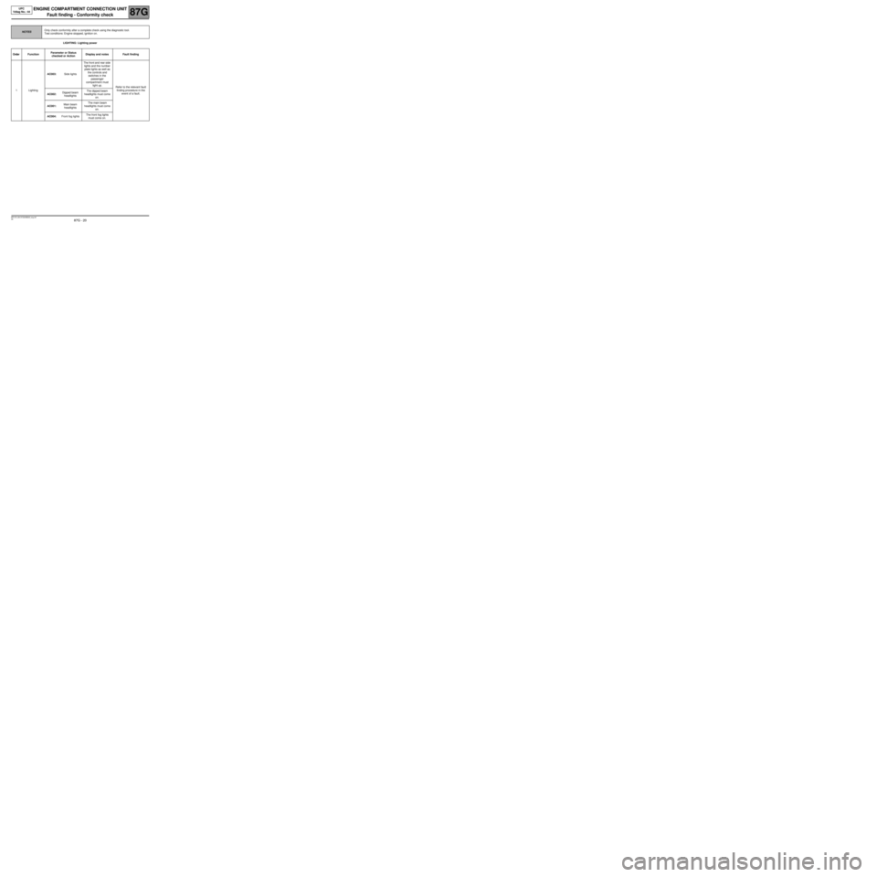
LIGHTING: Lighting power
NOTESOnly check conformity after a complete check using the diagnostic tool.
Test conditions: Engine stopped, ignition on.
Order FunctionParameter or Status
checked or Action Display and notes Fault finding
1LightingAC003:Side lightsThe front and rear side
lights and the number
plate lights as well as
the controls and
switches in the
passenger
compartment must
light up.
Refer to the relevant fault
finding procedure in the
event of a fault.
AC002:Dipped beam
headlightsThe dipped beam
headlights must come
on.
AC001:Main beam
headlightsThe main beam
headlights must come
on.
AC004:Front fog lightsThe front fog lights
must come on.
Page 26 of 56
87G - 26
ENGINE COMPARTMENT CONNECTION UNIT
Fault finding - Status and parameter summary table87G
V6 MR-372-J84-87G000$594_eng.mif
UPC
Vdiag No.: 44ENGINE COMPARTMENT CONNECTION UNIT
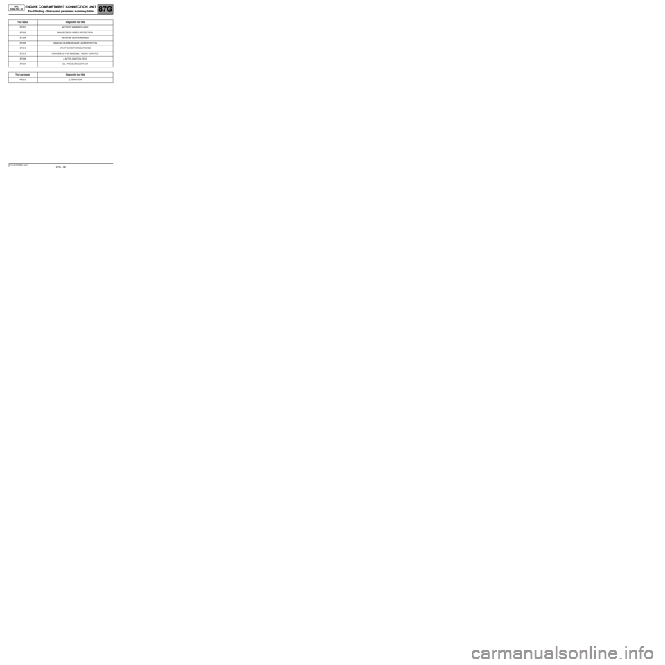
Fault finding - Status and parameter summary table
Tool status Diagnostic tool title
ET001 BATTERY WARNING LIGHT
ET002 WINDSCREEN WIPER PROTECTION
ET004 REVERSE GEAR ENGAGED
ET005 MANUAL GEARBOX GEAR LEVER POSITION
ET010 START CONDITIONS SATISFIED
ET013 HIGH SPEED FAN ASSEMBLY RELAY CONTROL
ET026 + AFTER IGNITION FEED
ET027 OIL PRESSURE CONTACT
Tool parameter Diagnostic tool title
PR010 ALTERNATOR
MR-372-J84-87G000$594_eng.mif
Page 27 of 56
87G - 27
ENGINE COMPARTMENT CONNECTION UNIT
Fault finding - Interpretation of statuses
87G
V6 MR-372-J84-87G000$660_eng.mif
UPC
Vdiag No.: 44ENGINE COMPARTMENT CONNECTION UNIT
Fault finding - Interpretation of statuses
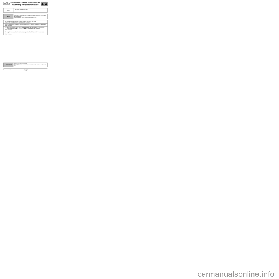
ET001
BATTERY WARNING LIGHT
NOTESCheck that the status is OUT with the engine running and LIT with the engine stopped
and the ignition on.
Check consistency with the instrument panel warning light.
With the engine running, check that the battery voltage is much higher than +12 V.
Perform a fault finding procedure on the charge circuit if necessary.
Check the status and the connection of connector PEM on the UPC and of the connections on the alternator.
Repair if necessary.
Turn off the ignition and ensure that there is insulation against +12 V and continuity in the connection:
UPC connector PEM track 8 Track 1 of the alternator 2-track connector
Repair if necessary.
With the ignition on, ensure that there is insulation against earth and the continuity in the connection:
UPC connector PEM track 8 Track 1 of the alternator 2-track connector
Repair if necessary.
AFTER REPAIRDeal with any other possible faults.
Switch off the ignition and carry out a road test followed by a test with the diagnostic
tool.
MR-372-J84-87G000$660_eng.mif
Page 29 of 56
87G - 29
ENGINE COMPARTMENT CONNECTION UNIT
Fault finding - Interpretation of statuses
87G
V6 MR-372-J84-87G000$660_eng.mif
UPC
Vdiag No.: 44
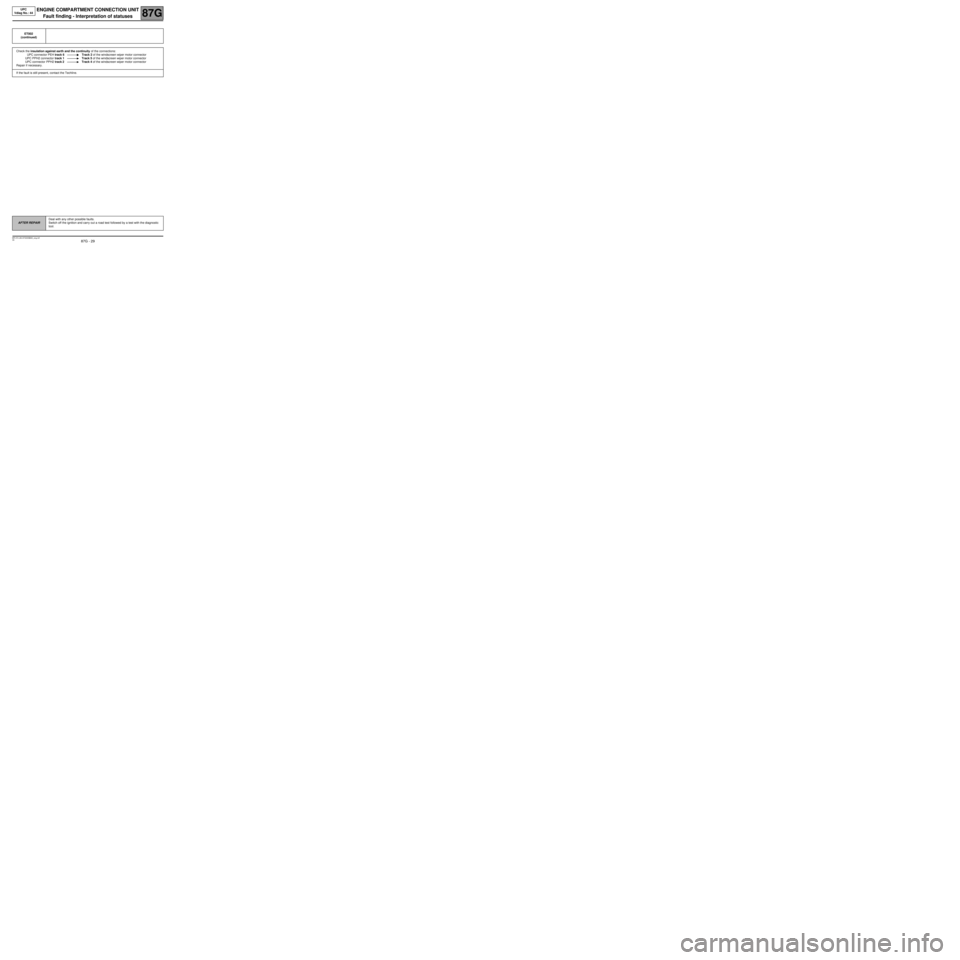
ET002
(continued)
Check the insulation against earth and the continuity of the connections:
UPC connector PEH track 6 Track 2 of the windscreen wiper motor connector
UPC PPH2 connector track 1 Track 5 of the windscreen wiper motor connector
UPC connector PPH2 track 2 Track 4 of the windscreen wiper motor connector
Repair if necessary.
If the fault is still present, contact the Techline.
AFTER REPAIRDeal with any other possible faults.
Switch off the ignition and carry out a road test followed by a test with the diagnostic
tool.
Page 30 of 56
87G - 30
ENGINE COMPARTMENT CONNECTION UNIT
Fault finding - Interpretation of statuses
87G
V6 MR-372-J84-87G000$660_eng.mif
UPC
Vdiag No.: 44
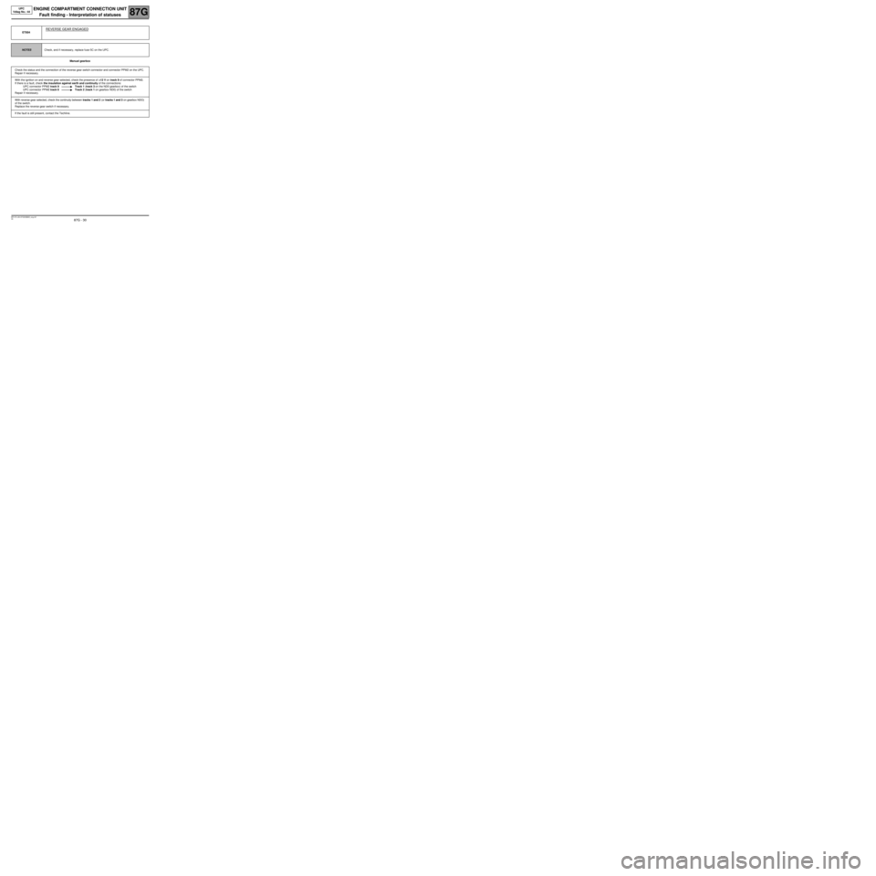
Manual gearbox ET004
REVERSE GEAR ENGAGED
NOTESCheck, and if necessary, replace fuse 5C on the UPC.
Check the status and the connection of the reverse gear switch connector and connector PPM2 on the UPC.
Repair if necessary.
With the ignition on and reverse gear selected, check the presence of +12 V on track 9 of connector PPM2.
If there is a fault, check the insulation against earth and continuity of the connections:
UPC connector PPM2 track 9 Track 1 (track 3 on the ND0 gearbox) of the switch
UPC connector PPM2 track 6 Track 2 (track 1 on gearbox ND0) of the switch
Repair if necessary.
With reverse gear selected, check the continuity between tracks 1 and 2 (or tracks 1 and 3 on gearbox NDO)
of the switch.
Replace the reverse gear switch if necessary.
If the fault is still present, contact the Techline.
Page 31 of 56
87G - 31
ENGINE COMPARTMENT CONNECTION UNIT
Fault finding - Interpretation of statuses
87G
V6 MR-372-J84-87G000$660_eng.mif
UPC
Vdiag No.: 44
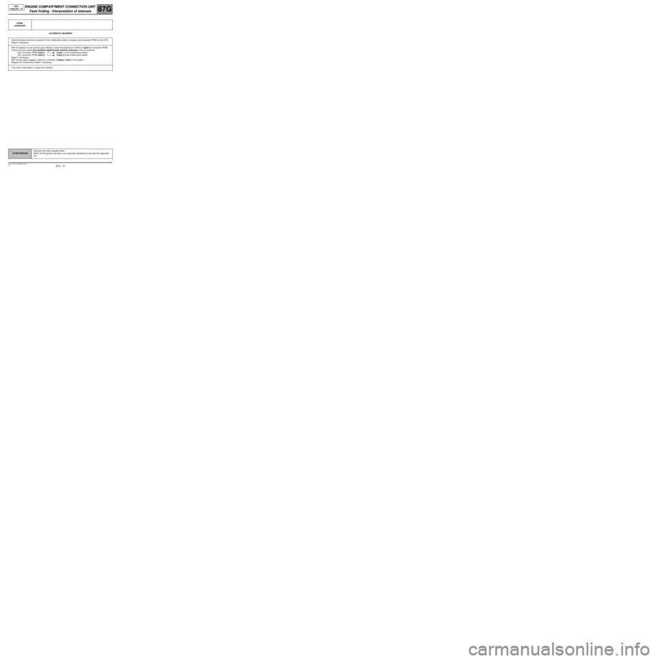
AUTOMATIC GEARBOX ET004
(continued)
Check the status and the connection of the multifunction switch connector and connector PPM2 on the UPC.
Repair if necessary.
With the ignition on and reverse gear selected, check the presence of +12 V on track 9 of connector PPM2.
If there is a fault, check the insulation against earth and the continuity of the connections:
UPC connector PPM2 track 9 Track 1 of the multifunction switch
UPC connector PPM2 track 6 Track 2 of the multifunction switch
Repair if necessary.
With reverse gear engaged, check the continuity of tracks 1 and 2 of the switch.
Replace the multifunction switch if necessary.
If the fault is still present, contact the Techline.
AFTER REPAIRDeal with any other possible faults.
Switch off the ignition and carry out a road test followed by a test with the diagnostic
tool.
Page 32 of 56
87G - 32
ENGINE COMPARTMENT CONNECTION UNIT
Fault finding - Interpretation of statuses
87G
V6 MR-372-J84-87G000$660_eng.mif
UPC
Vdiag No.: 44
ET005
POSITION OF GEAR LEVER IN MANUAL GEARBOX
NOTESCheck, and if necessary, replace fuse "5C" on the UPC.
Applicable on vehicles fitted with a manual gearbox only.
Check the status and the connection of the neutral switch connector and connectors PPM2 and PEM on the
UPC.
Repair if necessary.
With the ignition on and in neutral, check the presence of +12 V on track 6 of connector PEM. If there is a fault,
check the insulation against earth and the continuity of the connection between the switch and track 6 of
connector PEM on the UPC.
Check the operation of the switch:
There is continuity between tracks 1 and 2 of the switch when the gearbox is in neutral.
There is an open circuit between tracks 1 and 2 of the switch when a gear is selected.
If faulty, replace the switch.
With the ignition on, check the presence of +12 V on track 2 (track 1 on gearbox ND0) of the neutral switch
connector.
If there is a fault, check the insulation against earth and the continuity of the connection between the switch
and track 6 of connector PPM2 on the UPC.
If the fault is still present, contact the Techline.
AFTER REPAIRDeal with any other possible faults.
Switch off the ignition and carry out a road test followed by a test with the diagnostic
tool.
Page 33 of 56
87G - 33
ENGINE COMPARTMENT CONNECTION UNIT
Fault finding - Interpretation of statuses
87G
V6 MR-372-J84-87G000$660_eng.mif
UPC
Vdiag No.: 44
ET009
OIL PRESSURE CONTACT
NOTESCLOSED engine stopped, OPEN engine running.
Check the status and the connection of connectors PEM on the UPC and the oil pressure sensor.
Repair if necessary.
Make sure that the sensor is securely mounted on the engine.
Check the insulation against +12 V and the continuity of the connection between:
UPC connector PEM track 12 Track 1 pressure sensor
Repair if necessary.
If the fault is still present, contact the Techline.
AFTER REPAIRDeal with any other possible faults.
Switch off the ignition and carry out a road test followed by a test with the diagnostic
tool.