ignition RENAULT SCENIC 2010 J95 / 3.G Petrol Injection S3000 Injection Workshop Manual
[x] Cancel search | Manufacturer: RENAULT, Model Year: 2010, Model line: SCENIC, Model: RENAULT SCENIC 2010 J95 / 3.GPages: 230, PDF Size: 0.92 MB
Page 192 of 230
PETROL INJECTION
Fault finding - Interpretation of statuses
17B
17B - 192
PETROL INJECTION
Fault finding - Interpretation of statuses
17B
17B - 192V9 MR-372-J84-17B050$611.mif
S3000 Injection
Program No.: AD
Vdiag No.: 4C / 54
ET509
OBD DOWNSTREAM OXYGEN SENSOR HEATING CIRCUIT
NOTESThere must be no present or stored faults.
Check the cleanliness and condition of the downstream oxygen sensor and its connections.
Repair if necessary.
With the ignition on, check for + 12 V feed on track A of the downstream oxygen sensor connector.
If +12V is not present:
– disconnect the battery,
– disconnect the CN connector in the Protection and Switching Unit,
– check the cleanliness and condition of the connections,
– using the Universal bornier, check the continuity on the following connection:
Protection and Switching Unit, connector CN,
track 6track A of the downstream oxygen sensor
Reconnect the Protection and Switching Unit connector and reconnect the battery.
With the ignition on, if the +12V is still not present on the downstream oxygen sensor connector, there is a fault
in the Protection and Switching Unit.
Contact the Techline.
Disconnect the battery and the injection computer.
Check the cleanliness and condition of the connections.
Using the Universal bornier, check the insulation and continuity on the following connection:
Injection computer, connectorC, track L3 track B of the downstream oxygen sensor
Repair if necessary.
Measure the heating resistance between tracks A and B of the downstream oxygen sensor.
Replace the downstream oxygen sensor if the resistance is not approximately 9Ω at 20°C.
If the fault is still present, replace the downstream oxygen sensor.
AFTER REPAIRRepeat the conformity check from the start.
S3000_V4C_ET509/S3000_V54_ET509
Page 198 of 230
PETROL INJECTION
Fault finding - Interpretation of statuses
17B
17B - 198
PETROL INJECTION
Fault finding - Interpretation of statuses
17B
17B - 198V9 MR-372-J84-17B050$611.mif
S3000 Injection
Program No.: AD
Vdiag No.: 4C / 54
ET703
CRUISE CONTROL/SPEED LIMITER BUTTONS
NOTESSpecial notes:
Only perform the tests if the statuses do not correspond with the system programming
functions.
INACTIVEStatus ET703 becomes "INACTIVE" when none of the cruise control/speed limiter
buttons is pressed. These buttons are located on the steering wheel.
If status ET703 does not display "INACTIVE",
●check the condition of the cruise control/speed limiter +/- button and the condition of
its connector,
●check the condition of the cruise control/speed limiter R/0 button and the condition of
its connector.
INCREASEStatus ET703 becomes PLUS when the cruise control/speed limiter + button is pressed.
This button is on the steering wheel, on the left-hand side.
If status ET703 does not display PLUS, check the condition of the cruise control/speed
limiter +/- button, and the condition of its connector. Repair if necessary.
To carry out these checks and measurements in complete safety, observe the
recommendations for removing the driver's front airbag (see MR 364 Mechanical, 88C,
Airbag and seat belt pretensioners, Driver's front airbag, Removal - Refitting)
Measure the resistance on the following connection with the "+" button pressed:
Injection computer,
connector A, black, 32-track track D2 "+/-" button track 2.
connector A, black, 32-track track D3 "+/-" button track 1.
If the resistance is not approximately 300 Ω, check the continuity of the connection when
the button is not pressed.
If there is continuity, replace the +/- control button.
If there is a repair procedure (see Technical Note 6015A, Repairing electrical wiring,
Wiring: Precautions for repair), repair the wiring, otherwise replace it.
AFTER REPAIRDeal with any other faults. Clear the fault memory.
Switch off the ignition and carry out a road test followed by a test with the diagnostic
tool.
S3000_V4C_ET703/S3000_V54_ET703
Page 199 of 230
PETROL INJECTION
Fault finding - Interpretation of statuses
17B
17B - 199
PETROL INJECTION
Fault finding - Interpretation of statuses
17B
17B - 199V9 MR-372-J84-17B050$611.mif
S3000 Injection
Program No.: AD
Vdiag No.: 4C / 54
ET703
CONTINUED 1
DECREASEStatus ET703 becomes MINUS when the cruise control/speed limiter - button is pressed.
This button is on the steering wheel, on the left-hand side.
If status ET703 does not change to MINUS, check the condition of the cruise control/
speed limiter "+/-" button, and the condition of its connector. Repair if necessary.
To carry out these checks and measurements in complete safety, observe the
recommendations for removing the driver's front airbag (see MR 364 Mechanical, 88C,
Airbag and pretensioners, Driver's front airbag, Removal - Refitting).
Measure the resistance on the following connection with the "-" button pressed:
Injection computer,
connector A, black, 32-track track D2 "+/-" button track 2.
connector A, black, 32-track track D3 "+/-" button track 1.
If the resistance is not approximately 100Ω, check the continuity of the connection when
the button is not pressed.
If there is continuity, replace the "+/-" control button.
If there is a repair procedure (see Technical Note 6015A, Repairing electrical wiring,
Wiring: Precautions for repair), repair the wiring, otherwise replace it.
RESUMEStatus ET703 becomes RESUME when the cruise control/speed limiter R button is
pressed. This button is located on the steering wheel, to the right.
If status ET703 does not change to RESUME, check the condition of the cruise control/
speed limiter R/0 button, and the condition of its connector. Repair if necessary.
To carry out these checks and measurements in complete safety, observe the
recommendations for removing the driver's front airbag (see MR 364 Mechanical, 88C,
Airbag and pretensioners, Driver's front airbag, Removal - Refitting)
Measure the resistance of the following connection with the "R" button pressed:
Injection computer,
connector A, black, 32-track track D2 "+/-" button track 2.
connector A, black, 32-track track D3 "+/-" button track 1.
If the resistance is not approximately 900 Ω, check the continuity of the connection when
the button is not pressed.
If there is continuity, replace the "R/0" control button.
If there is a repair procedure (see Technical Note 6015A, Repairing electrical wiring,
Wiring: Precautions for repair), repair the wiring, otherwise replace it.
AFTER REPAIRDeal with any other faults. Clear the fault memory.
Switch off the ignition and carry out a road test followed by a test with the diagnostic
tool.
Page 200 of 230
PETROL INJECTION
Fault finding - Interpretation of statuses
17B
17B - 200
PETROL INJECTION
Fault finding - Interpretation of statuses
17B
17B - 200V9 MR-372-J84-17B050$611.mif
S3000 Injection
Program No.: AD
Vdiag No.: 4C / 54
ET703
CONTINUED 2
SUSPENDStatus ET703 becomes SUSPEND when the cruise control/speed limiter 0 button is
pressed. This button is located on the steering wheel, to the right.
If status ET703 does not change to SUSPEND, check the condition of the cruise control/
speed limiter R/0 button, and the condition of its connector.
To carry out these checks and measurements in complete safety, observe the
recommendations for removing the driver's front airbag (see MR 364 Mechanical, 88C,
Airbag and pretensioners, Driver's front airbag, Removal - Refitting)
Measure the resistance of the following connection with the "0" button pressed:
Injection computer,
connector A, black, 32-track track D2 "+/-" button track 2.
connector A, black, 32-track track D3 "+/-" button track 1.
If the resistance is not approximately 0 Ω, replace the R/0 control button.
If there is continuity, replace the "R/0" control button.
If there is a repair procedure (see Technical Note 6015A, Repairing electrical wiring,
Wiring: Precautions for repair), repair the wiring, otherwise replace it.
AFTER REPAIRDeal with any other faults. Clear the fault memory.
Switch off the ignition and carry out a road test followed by a test with the diagnostic
tool.
Page 201 of 230
PETROL INJECTION
Fault finding - Interpretation of statuses
17B
17B - 201
PETROL INJECTION
Fault finding - Interpretation of statuses
17B
17B - 201V9 MR-372-J84-17B050$611.mif
S3000 Injection
Program No.: AD
Vdiag No.: 4C / 54
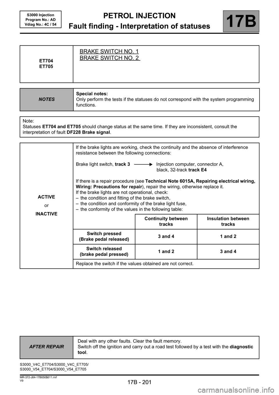
ET704
ET705
BRAKE SWITCH NO. 1
BRAKE SWITCH NO. 2
NOTESSpecial notes:
Only perform the tests if the statuses do not correspond with the system programming
functions.
Note:
Statuses ET704 and ET705 should change status at the same time. If they are inconsistent, consult the
interpretation of fault DF228 Brake signal.
ACTIVE
or
INACTIVEIf the brake lights are working, check the continuity and the absence of interference
resistance between the following connections:
Brake light switch, track 3 Injection computer, connector A,
black, 32-track track E4
If there is a repair procedure (see Technical Note 6015A, Repairing electrical wiring,
Wiring: Precautions for repair), repair the wiring, otherwise replace it.
If the brake lights are not operational, check:
– the condition and fitting of the brake switch,
– the condition and conformity of the brake light fuse,
– the conformity of the values in the following table:
Continuity between
tracksInsulation between
tracks
Switch pressed
(Brake pedal released)3 and 4 1 and 2
Switch released
(brake pedal pressed)1 and 2 3 and 4
Replace the switch if the values obtained are not correct.
AFTER REPAIRDeal with any other faults. Clear the fault memory.
Switch off the ignition and carry out a road test followed by a test with the diagnostic
tool.
S3000_V4C_ET704/S3000_V4C_ET705/
S3000_V54_ET704/S3000_V54_ET705
Page 203 of 230

PETROL INJECTION
Fault finding - Parameter summary table
17B
17B - 203
17B
17B - 203V9 MR-372-J84-17B050$658.mif
S3000 Injection
Program No.: AD
Vdiag No.: 4C / 54
* OCR: Opening Cycle Ratio
* SV: Solenoid valveTool parameter Diagnostic tool title
PR118Measured throttle position gang 1
PR119Measured throttle position gang 2
PR125Power absorbed by the air conditioning compressor
PR126Advance after anti-pinking correction
PR138Richness correction
PR143Self-adapting richness gain
PR144Self-adapting richness offset
PR147Pedal potentiometer voltage gang 1
PR148Pedal potentiometer voltage gang 2
PR312Inlet manifold vacuum
PR424Programming the no-load position value
PR427Average pinking signal
PR429Measured throttle position
PR448Ignition advance
PR499Pedal no load programming
PR538Measured throttle voltage, gang 2
PR539Measured throttle voltage, gang 1
PR568Pedal position gang 1
PR569Pedal position gang 2
PR588Motorised throttle lower stop gang 2
PR589Motorised throttle upper stop gang 1
PR590Motorised throttle upper stop gang 2
PR593Motorised throttle in safe mode gang 1
PR594Motorised throttle in safe mode gang 2
PR597Motorised throttle in safe mode
PR745Camshaft dephaser position setpoint
PR846Turbocharging SV* OCR*
PR876Camshaft dephaser solenoid valve control OCR*
Page 206 of 230
PETROL INJECTION
Fault finding - Interpretation of parameters
17B
17B - 206
PETROL INJECTION
Fault finding - Interpretation of parameters
17B
17B - 206V9 MR-372-J84-17B050$705.mif
S3000 Injection
Program No.: AD
Vdiag No.: 4C / 54
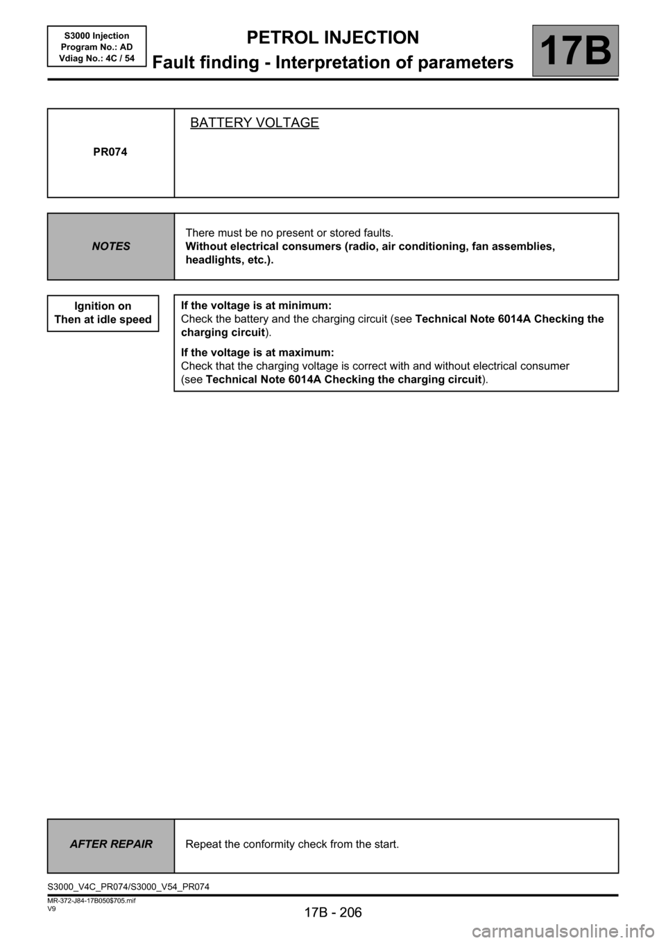
PR074
BATTERY VOLTAGE
NOTESThere must be no present or stored faults.
Without electrical consumers (radio, air conditioning, fan assemblies,
headlights, etc.).
Ignition on
Then at idle speed
If the voltage is at minimum:
Check the battery and the charging circuit (see Technical Note 6014A Checking the
charging circuit).
If the voltage is at maximum:
Check that the charging voltage is correct with and without electrical consumer
(seeTechnical Note 6014A Checking the charging circuit).
AFTER REPAIRRepeat the conformity check from the start.
S3000_V4C_PR074/S3000_V54_PR074
Page 211 of 230

PETROL INJECTION
Fault finding - Interpretation of parameters
17B
17B - 211
PETROL INJECTION
Fault finding - Interpretation of parameters
17B
17B - 211V9 MR-372-J84-17B050$705.mif
S3000 Injection
Program No.: AD
Vdiag No.: 4C / 54
PR099
CONTINUED
Replace the downstream oxygen sensor.
If the fault is still present, the catalytic converter is certainly damaged.
If the catalytic converter is defective, determine the cause of the destruction, otherwise the new catalytic
converter may be damaged in turn.
Remove the catalytic converter.
Various things may destroy a catalytic converter:
–deformation (impact),
–thermal shock (cold water splashed onto a hot catalytic converter can damage it),
–defective injector or ignition: the catalytic converter is damaged by contact with fuel (coil fault, coil control fault,
injector jammed open),
–injector leak,
–abnormal oil or coolant consumption (defective cylinder head gasket),
–use of a fuel additive or other equivalent product (obtain information from the customer because this type of
product can contaminate the catalytic converter and render it useless sooner or later).
Look up the service history of the vehicle or, if this is not possible, ask the customer if the vehicle has had injection
or ignition faults.
If the cause of the catalytic converter damage has been found and the fault has disappeared, replace the
catalytic converter.
AFTER REPAIRRepeat the conformity check from the start.
Page 214 of 230
PETROL INJECTION
Fault finding - Interpretation of commands
17B
17B - 214
PETROL INJECTION
Fault finding - Interpretation of commands
17B
17B - 214V9 MR-372-J84-17B050$799.mif
S3000 Injection
Program No.: AD
Vdiag No.: 4C / 54PETROL INJECTION
Fault finding - Interpretation of commands
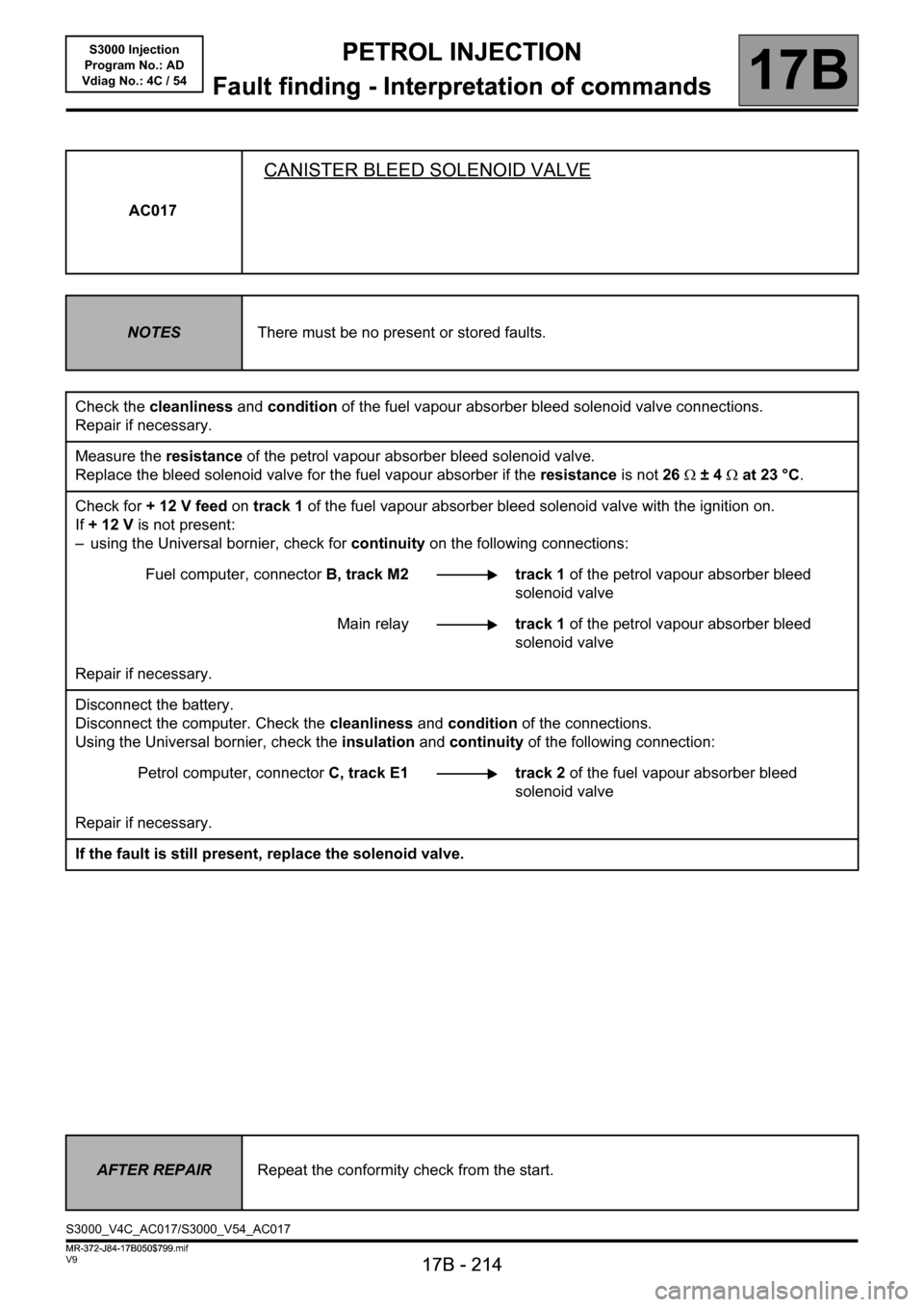
AC017
CANISTER BLEED SOLENOID VALVE
NOTESThere must be no present or stored faults.
Check the cleanliness and condition of the fuel vapour absorber bleed solenoid valve connections.
Repair if necessary.
Measure the resistance of the petrol vapour absorber bleed solenoid valve.
Replace the bleed solenoid valve for the fuel vapour absorber if the resistance is not 26Ω ±4Ω at 23 °C.
Check for + 12 V feed on track 1 of the fuel vapour absorber bleed solenoid valve with the ignition on.
If +12V is not present:
– using the Universal bornier, check for continuity on the following connections:
Fuel computer, connectorB, track M2 track 1 of the petrol vapour absorber bleed
solenoid valve
Main relaytrack 1 of the petrol vapour absorber bleed
solenoid valve
Repair if necessary.
Disconnect the battery.
Disconnect the computer. Check the cleanliness and condition of the connections.
Using the Universal bornier, check the insulation and continuity of the following connection:
Petrol computer, connector C, track E1 track 2 of the fuel vapour absorber bleed
solenoid valve
Repair if necessary.
If the fault is still present, replace the solenoid valve.
AFTER REPAIRRepeat the conformity check from the start.
S3000_V4C_AC017/S3000_V54_AC017
MR-372-J84-17B050$799.mif
Page 215 of 230
PETROL INJECTION
Fault finding - Interpretation of commands
17B
17B - 215
PETROL INJECTION
Fault finding - Interpretation of commands
17B
17B - 215V9 MR-372-J84-17B050$799.mif
S3000 Injection
Program No.: AD
Vdiag No.: 4C / 54
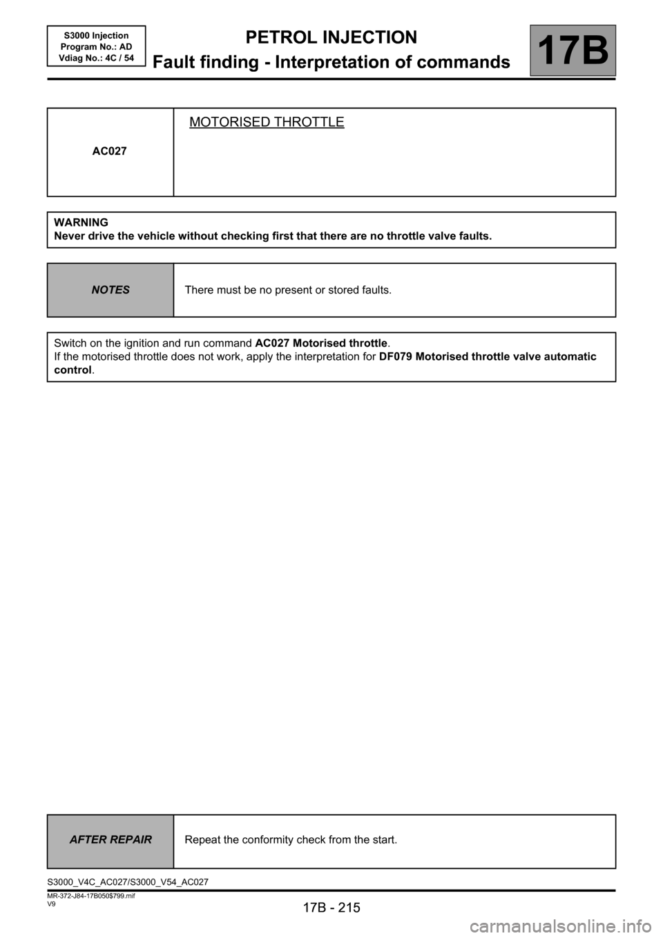
AC027
MOTORISED THROTTLE
WARNING
Never drive the vehicle without checking first that there are no throttle valve faults.
NOTESThere must be no present or stored faults.
Switch on the ignition and run command AC027 Motorised throttle.
If the motorised throttle does not work, apply the interpretation for DF079 Motorised throttle valve automatic
control.
AFTER REPAIRRepeat the conformity check from the start.
S3000_V4C_AC027/S3000_V54_AC027