ignition RENAULT SCENIC 2010 J95 / 3.G Petrol Injection S3000 Injection Manual Online
[x] Cancel search | Manufacturer: RENAULT, Model Year: 2010, Model line: SCENIC, Model: RENAULT SCENIC 2010 J95 / 3.GPages: 230, PDF Size: 0.92 MB
Page 168 of 230

PETROL INJECTION
Fault finding - Status summary table
17B
17B - 168
PETROL INJECTION
Fault finding - Status summary table
17B
17B - 168V9 MR-372-J84-17B050$564.mif
S3000 Injection
Program No.: AD
Vdiag No.: 4C / 54PETROL INJECTION
Fault finding - Status summary table
Tool status Diagnostic tool title
ET001+ After ignition computer feed
ET003Engine immobiliser
ET004Air conditioning authorisation
ET006Code programmed
ET021High speed fan assembly request
ET022Low speed fan assembly request
ET023Fast idle speed request
ET042Cruise control/speed limiter
ET047Fuel pump control circuit
ET048Actuator relay control
ET050Canister bleed control
ET051Throttle stop programming
ET052Upstream O
2 sensor heating
ET053Downstream O
2 sensor heating
ET054Idle speed regulation
ET056Richness double loop
ET057Misfiring on cylinder 1
ET058Misfiring on cylinder 2
ET059Misfiring on cylinder 3
ET060Misfiring on cylinder 4
ET061Cylinder 1 recognition
ET062Flywheel signal
ET063Park/Neutral position
ET064Level 1 injection fault
ET065Level 2 Injection fault
ET066LPG fault
ET067LPG ready
ET068LPG tank empty
ET071Transition from petrol mode to LPG mode
ET072Transition from LPG mode to petrol mode
ET073Conditions for switching to LPG mode
ET075Pedal released and throttle closed
MR-372-J84-17B050$564.mif
Page 170 of 230
PETROL INJECTION
Fault finding - Interpretation of statuses
17B
17B - 170
PETROL INJECTION
Fault finding - Interpretation of statuses
17B
17B - 170V9 MR-372-J84-17B050$611.mif
S3000 Injection
Program No.: AD
Vdiag No.: 4C / 54PETROL INJECTION
Fault finding - Interpretation of statuses
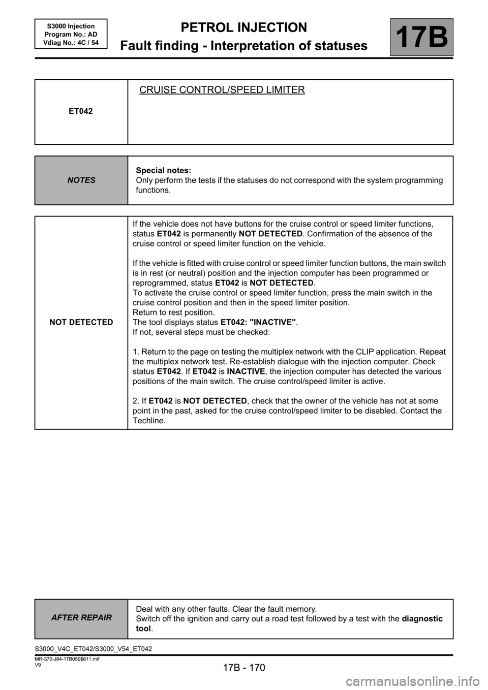
ET042
CRUISE CONTROL/SPEED LIMITER
NOTESSpecial notes:
Only perform the tests if the statuses do not correspond with the system programming
functions.
NOT DETECTEDIf the vehicle does not have buttons for the cruise control or speed limiter functions,
status ET042 is permanently NOT DETECTED. Confirmation of the absence of the
cruise control or speed limiter function on the vehicle.
If the vehicle is fitted with cruise control or speed limiter function buttons, the main switch
is in rest (or neutral) position and the injection computer has been programmed or
reprogrammed, status ET042 is NOT DETECTED.
To activate the cruise control or speed limiter function, press the main switch in the
cruise control position and then in the speed limiter position.
Return to rest position.
The tool displays status ET042: "INACTIVE".
If not, several steps must be checked:
1. Return to the page on testing the multiplex network with the CLIP application. Repeat
the multiplex network test. Re-establish dialogue with the injection computer. Check
status ET042. If ET042 is INACTIVE, the injection computer has detected the various
positions of the main switch. The cruise control/speed limiter is active.
2. If ET042 is NOT DETECTED, check that the owner of the vehicle has not at some
point in the past, asked for the cruise control/speed limiter to be disabled. Contact the
Techline.
AFTER REPAIRDeal with any other faults. Clear the fault memory.
Switch off the ignition and carry out a road test followed by a test with the diagnostic
tool.
S3000_V4C_ET042/S3000_V54_ET042
MR-372-J84-17B050$611.mif
Page 171 of 230
PETROL INJECTION
Fault finding - Interpretation of statuses
17B
17B - 171
PETROL INJECTION
Fault finding - Interpretation of statuses
17B
17B - 171V9 MR-372-J84-17B050$611.mif
S3000 Injection
Program No.: AD
Vdiag No.: 4C / 54
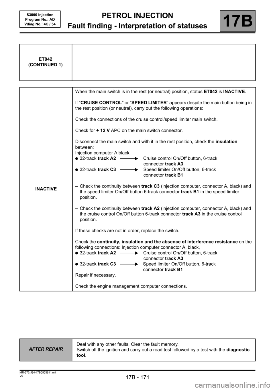
ET042
(CONTINUED 1)
INACTIVEWhen the main switch is in the rest (or neutral) position, status ET042 is INACTIVE.
If "CRUISE CONTROL" or "SPEED LIMITER" appears despite the main button being in
the rest position (or neutral), carry out the following operations:
Check the connections of the cruise control/speed limiter main switch.
Check for + 12 V APC on the main switch connector.
Disconnect the main switch and with it in the rest position, check the insulation
between:
Injection computer A black,
●32-track track A2 Cruise control On/Off button, 6-track
connector track A3
●32-track track C3 Speed limiter On/Off button, 6-track
connector track B1
– Check the continuity between track C3 (injection computer, connector A, black) and
the speed limiter On/Off button 6-track connector track B1 in the speed limiter
position.
– Check the continuity between track A2 (injection computer, connector A, black) and
the cruise control On/Off button 6-track connector track A3 in the cruise control
position.
If these checks are not in order, replace the switch.
Check the continuity, insulation and the absence of interference resistance on the
following connections: Injection computer connector A, black,
●32-track track A2 Cruise control On/Off button, 6-track
connector track A3
●32-track track C3 Speed limiter On/Off button, 6-track
connector track B1
Repair if necessary.
Check the engine management computer connections.
AFTER REPAIRDeal with any other faults. Clear the fault memory.
Switch off the ignition and carry out a road test followed by a test with the diagnostic
tool.
Page 172 of 230
PETROL INJECTION
Fault finding - Interpretation of statuses
17B
17B - 172
PETROL INJECTION
Fault finding - Interpretation of statuses
17B
17B - 172V9 MR-372-J84-17B050$611.mif
S3000 Injection
Program No.: AD
Vdiag No.: 4C / 54
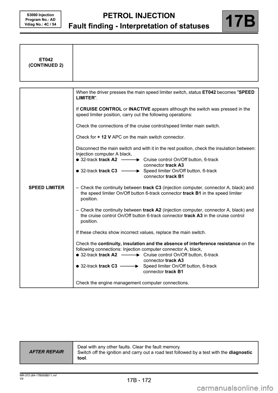
ET042
(CONTINUED 2)
SPEED LIMITERWhen the driver presses the main speed limiter switch, status ET042 becomes "SPEED
LIMITER".
If CRUISE CONTROL or INACTIVE appears although the switch was pressed in the
speed limiter position, carry out the following operations:
Check the connections of the cruise control/speed limiter main switch.
Check for + 12 V APC on the main switch connector.
Disconnect the main switch and with it in the rest position, check the insulation between:
Injection computer A black,
●32-track track A2 Cruise control On/Off button, 6-track
connector track A3
●32-track track C3 Speed limiter On/Off button, 6-track
connector track B1
– Check the continuity between track C3 (injection computer, connector A, black) and
the speed limiter On/Off button 6-track connector track B1 in the speed limiter
position.
– Check the continuity between track A2 (injection computer, connector A, black) and
the cruise control On/Off button 6-track connector track A3 in the cruise control
position.
If these checks show incorrect values, replace the main switch.
Check the continuity, insulation and the absence of interference resistance on the
following connections: Injection computer connector A, black,
●32-track track A2 Cruise control On/Off button, 6-track
connector track A3
●32-track track C3Speed limiter On/Off button, 6-track
connector track B1
Check the engine management computer connections.
AFTER REPAIRDeal with any other faults. Clear the fault memory.
Switch off the ignition and carry out a road test followed by a test with the diagnostic
tool.
Page 173 of 230
PETROL INJECTION
Fault finding - Interpretation of statuses
17B
17B - 173
PETROL INJECTION
Fault finding - Interpretation of statuses
17B
17B - 173V9 MR-372-J84-17B050$611.mif
S3000 Injection
Program No.: AD
Vdiag No.: 4C / 54
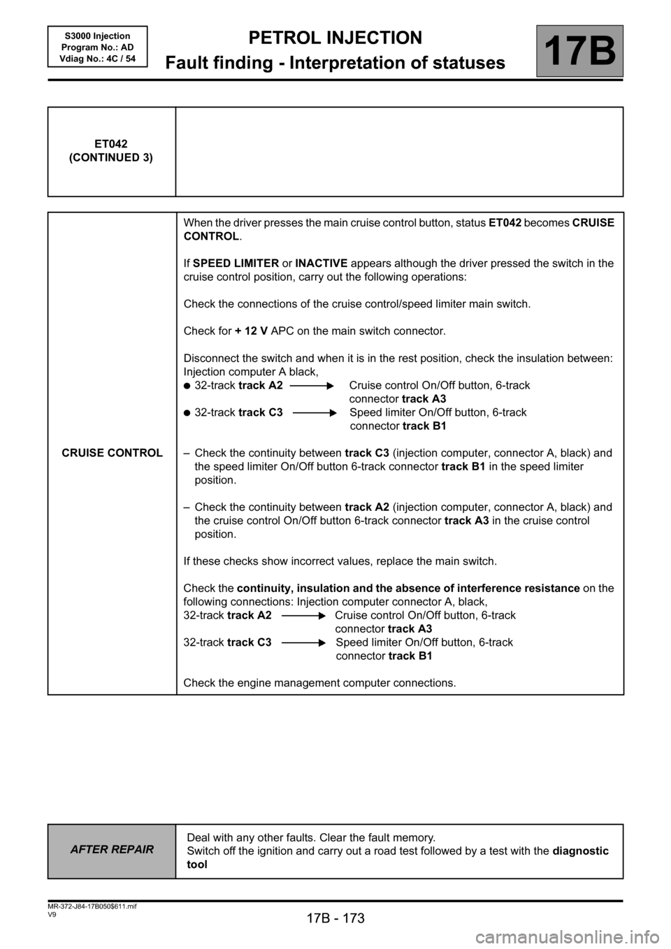
ET042
(CONTINUED 3)
CRUISE CONTROLWhen the driver presses the main cruise control button, status ET042 becomes CRUISE
CONTROL.
If SPEED LIMITER or INACTIVE appears although the driver pressed the switch in the
cruise control position, carry out the following operations:
Check the connections of the cruise control/speed limiter main switch.
Check for + 12 V APC on the main switch connector.
Disconnect the switch and when it is in the rest position, check the insulation between:
Injection computer A black,
●32-track track A2 Cruise control On/Off button, 6-track
connector track A3
●32-track track C3 Speed limiter On/Off button, 6-track
connector track B1
– Check the continuity between track C3 (injection computer, connector A, black) and
the speed limiter On/Off button 6-track connector track B1 in the speed limiter
position.
– Check the continuity between track A2 (injection computer, connector A, black) and
the cruise control On/Off button 6-track connector track A3 in the cruise control
position.
If these checks show incorrect values, replace the main switch.
Check the continuity, insulation and the absence of interference resistance on the
following connections: Injection computer connector A, black,
32-track track A2 Cruise control On/Off button, 6-track
connector track A3
32-track track C3 Speed limiter On/Off button, 6-track
connector track B1
Check the engine management computer connections.
AFTER REPAIRDeal with any other faults. Clear the fault memory.
Switch off the ignition and carry out a road test followed by a test with the diagnostic
tool
Page 175 of 230
PETROL INJECTION
Fault finding - Interpretation of statuses
17B
17B - 175
PETROL INJECTION
Fault finding - Interpretation of statuses
17B
17B - 175V9 MR-372-J84-17B050$611.mif
S3000 Injection
Program No.: AD
Vdiag No.: 4C / 54
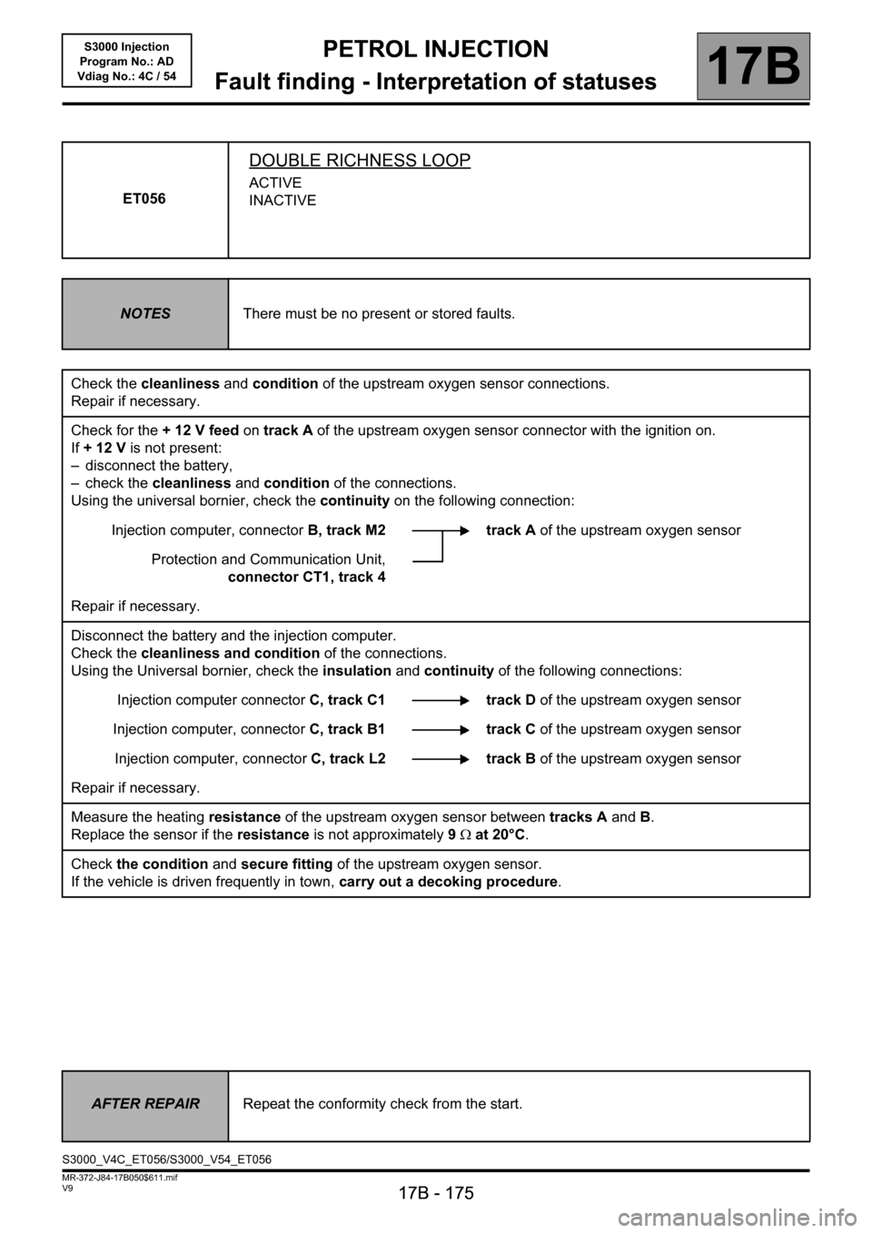
ET056
DOUBLE RICHNESS LOOP
ACTIVE
INACTIVE
NOTESThere must be no present or stored faults.
Check the cleanliness and condition of the upstream oxygen sensor connections.
Repair if necessary.
Check for the + 12 V feed on track A of the upstream oxygen sensor connector with the ignition on.
If +12V is not present:
– disconnect the battery,
– check the cleanliness and condition of the connections.
Using the universal bornier, check the continuity on the following connection:
Injection computer, connectorB, track M2 track A of the upstream oxygen sensor
Protection and Communication Unit,
connector CT1, track 4
Repair if necessary.
Disconnect the battery and the injection computer.
Check the cleanliness and condition of the connections.
Using the Universal bornier, check the insulation and continuity of the following connections:
Injection computer connectorC, track C1 track D of the upstream oxygen sensor
Injection computer, connectorC, track B1 track C of the upstream oxygen sensor
Injection computer, connectorC, track L2 track B of the upstream oxygen sensor
Repair if necessary.
Measure the heating resistance of the upstream oxygen sensor between tracks A and B.
Replace the sensor if the resistance is not approximately 9Ω at 20°C.
Check the condition and secure fitting of the upstream oxygen sensor.
If the vehicle is driven frequently in town, carry out a decoking procedure.
AFTER REPAIRRepeat the conformity check from the start.
S3000_V4C_ET056/S3000_V54_ET056
Page 176 of 230
PETROL INJECTION
Fault finding - Interpretation of statuses
17B
17B - 176
PETROL INJECTION
Fault finding - Interpretation of statuses
17B
17B - 176V9 MR-372-J84-17B050$611.mif
S3000 Injection
Program No.: AD
Vdiag No.: 4C / 54
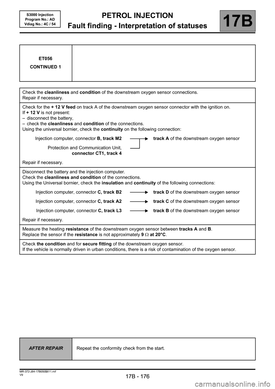
ET056
CONTINUED 1
Check the cleanliness and condition of the downstream oxygen sensor connections.
Repair if necessary.
Check for the + 12 V feed on track A of the downstream oxygen sensor connector with the ignition on.
If +12V is not present:
– disconnect the battery,
– check the cleanliness and condition of the connections.
Using the universal bornier, check the continuity on the following connection:
Injection computer, connectorB, track M2 track A of the downstream oxygen sensor
Protection and Communication Unit,
connector CT1, track 4
Repair if necessary.
Disconnect the battery and the injection computer.
Check the cleanliness and condition of the connections.
Using the Universal bornier, check the insulation and continuity of the following connections:
Injection computer, connectorC, track B2 track D of the downstream oxygen sensor
Injection computer, connectorC, track A2 track C of the downstream oxygen sensor
Injection computer, connectorC, track L3 track B of the downstream oxygen sensor
Repair if necessary.
Measure the heating resistance of the downstream oxygen sensor between tracks A and B.
Replace the sensor if the resistance is not approximately 9Ω at 20°C.
Check the condition and for secure fitting of the downstream oxygen sensor.
If the vehicle is normally driven in urban conditions, there is a risk of contamination of the oxygen sensor.
AFTER REPAIRRepeat the conformity check from the start.
Page 178 of 230
PETROL INJECTION
Fault finding - Interpretation of statuses
17B
17B - 178
PETROL INJECTION
Fault finding - Interpretation of statuses
17B
17B - 178V9 MR-372-J84-17B050$611.mif
S3000 Injection
Program No.: AD
Vdiag No.: 4C / 54
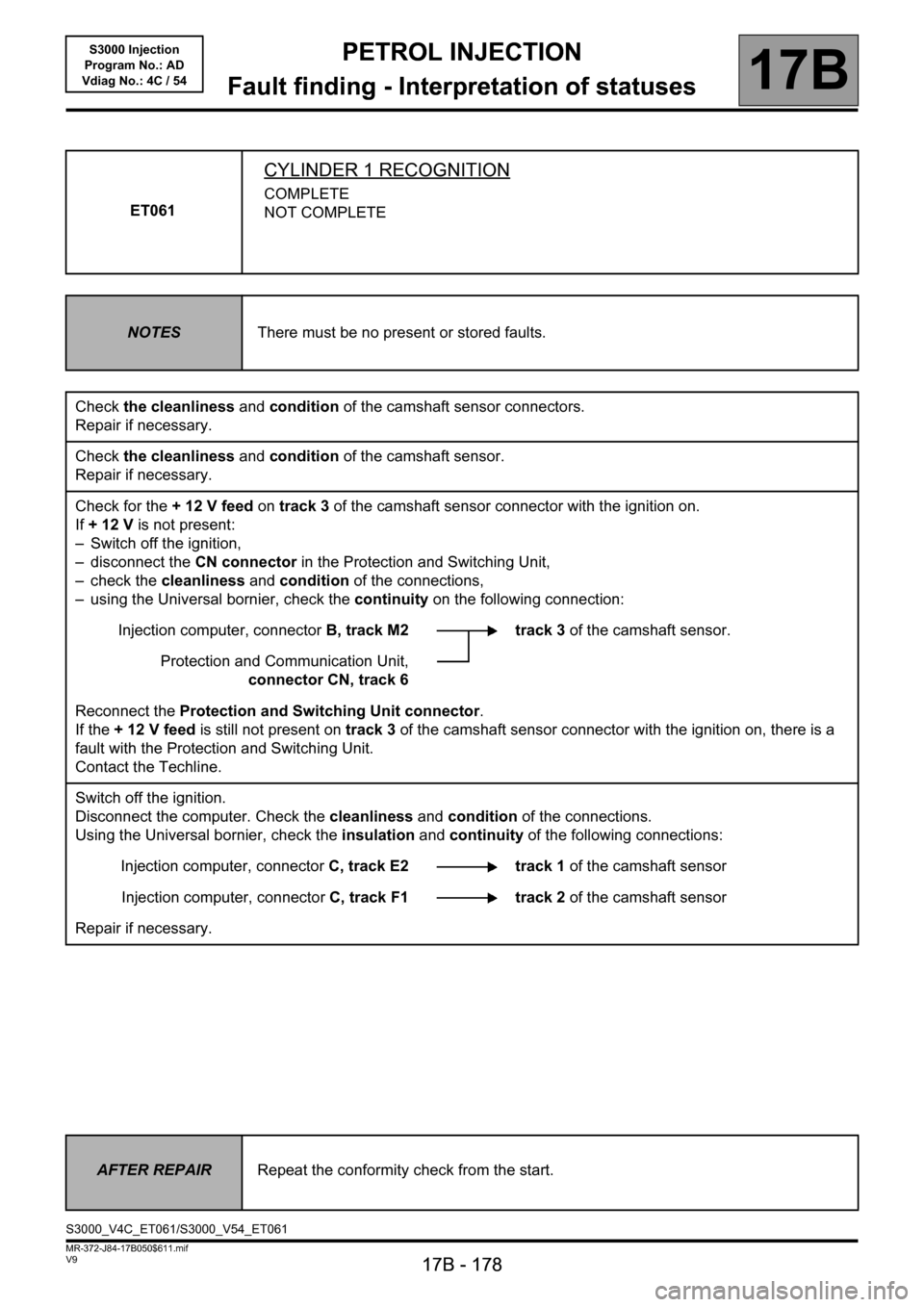
ET061
CYLINDER 1 RECOGNITION
COMPLETE
NOT COMPLETE
NOTESThere must be no present or stored faults.
Check the cleanliness and condition of the camshaft sensor connectors.
Repair if necessary.
Check the cleanliness and condition of the camshaft sensor.
Repair if necessary.
Check for the + 12 V feed on track 3 of the camshaft sensor connector with the ignition on.
If +12V is not present:
– Switch off the ignition,
– disconnect the CN connector in the Protection and Switching Unit,
– check the cleanliness and condition of the connections,
– using the Universal bornier, check the continuity on the following connection:
Injection computer, connectorB, track M2 track 3 of the camshaft sensor.
Protection and Communication Unit,
connector CN, track 6
Reconnect the Protection and Switching Unit connector.
If the + 12 V feed is still not present on track 3 of the camshaft sensor connector with the ignition on, there is a
fault with the Protection and Switching Unit.
Contact the Techline.
Switch off the ignition.
Disconnect the computer. Check the cleanliness and condition of the connections.
Using the Universal bornier, check the insulation and continuity of the following connections:
Injection computer, connectorC, track E2 track 1 of the camshaft sensor
Injection computer, connectorC, track F1 track 2 of the camshaft sensor
Repair if necessary.
AFTER REPAIRRepeat the conformity check from the start.
S3000_V4C_ET061/S3000_V54_ET061
Page 180 of 230
PETROL INJECTION
Fault finding - Interpretation of statuses
17B
17B - 180
PETROL INJECTION
Fault finding - Interpretation of statuses
17B
17B - 180V9 MR-372-J84-17B050$611.mif
S3000 Injection
Program No.: AD
Vdiag No.: 4C / 54
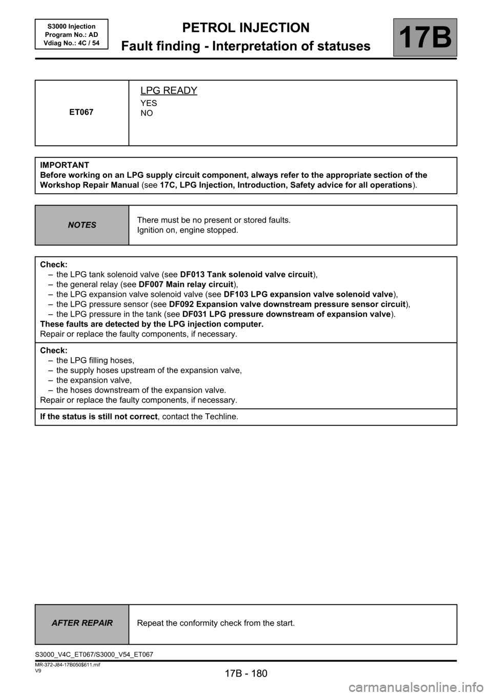
ET067
LPG READY
YES
NO
IMPORTANT
Before working on an LPG supply circuit component, always refer to the appropriate section of the
Workshop Repair Manual (see17C, LPG Injection, Introduction, Safety advice for all operations).
NOTESThere must be no present or stored faults.
Ignition on, engine stopped.
Check:
– the LPG tank solenoid valve (see DF013 Tank solenoid valve circuit),
– the general relay (see DF007 Main relay circuit),
– the LPG expansion valve solenoid valve (see DF103 LPG expansion valve solenoid valve),
– the LPG pressure sensor (see DF092 Expansion valve downstream pressure sensor circuit),
– the LPG pressure in the tank (see DF031 LPG pressure downstream of expansion valve).
These faults are detected by the LPG injection computer.
Repair or replace the faulty components, if necessary.
Check:
– the LPG filling hoses,
– the supply hoses upstream of the expansion valve,
– the expansion valve,
– the hoses downstream of the expansion valve.
Repair or replace the faulty components, if necessary.
If the status is still not correct, contact the Techline.
AFTER REPAIRRepeat the conformity check from the start.
S3000_V4C_ET067/S3000_V54_ET067
Page 181 of 230
PETROL INJECTION
Fault finding - Interpretation of statuses
17B
17B - 181
PETROL INJECTION
Fault finding - Interpretation of statuses
17B
17B - 181V9 MR-372-J84-17B050$611.mif
S3000 Injection
Program No.: AD
Vdiag No.: 4C / 54
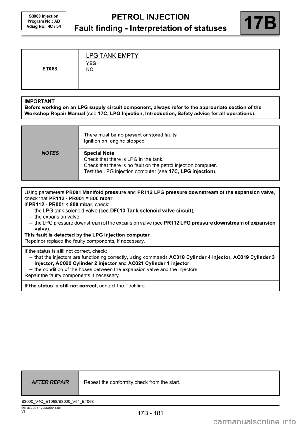
ET068
LPG TANK EMPTY
YES
NO
IMPORTANT
Before working on an LPG supply circuit component, always refer to the appropriate section of the
Workshop Repair Manual (see17C, LPG Injection, Introduction, Safety advice for all operations).
NOTESThere must be no present or stored faults.
Ignition on, engine stopped.
Special Note
Check that there is LPG in the tank.
Check that there is no fault on the petrol injection computer.
Test the LPG injection computer (see17C, LPG injection).
Using parameters PR001 Manifold pressure and PR112 LPG pressure downstream of the expansion valve,
check that PR112 - PR001 = 800 mbar.
If PR112 - PR001 < 800 mbar, check:
– the LPG tank solenoid valve (see DF013 Tank solenoid valve circuit),
– the expansion valve,
– the LPG pressure downstream of the expansion valve (see PR112 LPG pressure downstream of expansion
valve).
This fault is detected by the LPG injection computer.
Repair or replace the faulty components, if necessary.
If the status is still not correct, check:
– that the injectors are functioning correctly, using commands AC018 Cylinder 4 injector, AC019 Cylinder 3
injector, AC020 Cylinder 2 injector and AC021 Cylinder 1 injector.
– the condition of the hoses between the expansion valve and the injectors.
Repair the faulty components if necessary.
If the status is still not correct, contact the Techline.
AFTER REPAIRRepeat the conformity check from the start.
S3000_V4C_ET068/S3000_V54_ET068